Publisher’s version / Version de l'éditeur:
Journal of Engineering for Gas Turbines and Power, 130, 6, pp.
062808-1-062808-6, 2008-11
READ THESE TERMS AND CONDITIONS CAREFULLY BEFORE USING THIS WEBSITE. https://nrc-publications.canada.ca/eng/copyright
Vous avez des questions? Nous pouvons vous aider. Pour communiquer directement avec un auteur, consultez la première page de la revue dans laquelle son article a été publié afin de trouver ses coordonnées. Si vous n’arrivez pas à les repérer, communiquez avec nous à PublicationsArchive-ArchivesPublications@nrc-cnrc.gc.ca.
Questions? Contact the NRC Publications Archive team at
PublicationsArchive-ArchivesPublications@nrc-cnrc.gc.ca. If you wish to email the authors directly, please see the first page of the publication for their contact information.
NRC Publications Archive
Archives des publications du CNRC
This publication could be one of several versions: author’s original, accepted manuscript or the publisher’s version. / La version de cette publication peut être l’une des suivantes : la version prépublication de l’auteur, la version acceptée du manuscrit ou la version de l’éditeur.
For the publisher’s version, please access the DOI link below./ Pour consulter la version de l’éditeur, utilisez le lien DOI ci-dessous.
https://doi.org/10.1115/1.2939003
Access and use of this website and the material on it are subject to the Terms and Conditions set forth at
An Improved Phenomenological Soot Formation Submodel for
Three-Dimensional Diesel Engine Simulations : Extension to Agglomeration
of Particles into Clusters
Boulanger, Joan; Neill, W. Stuart; Liu, Fengshan; Smallwood, Gregory J.
https://publications-cnrc.canada.ca/fra/droits
L’accès à ce site Web et l’utilisation de son contenu sont assujettis aux conditions présentées dans le site LISEZ CES CONDITIONS ATTENTIVEMENT AVANT D’UTILISER CE SITE WEB.
NRC Publications Record / Notice d'Archives des publications de CNRC:
https://nrc-publications.canada.ca/eng/view/object/?id=3fa612e5-048b-4156-bbf4-00ce6b365e46
https://publications-cnrc.canada.ca/fra/voir/objet/?id=3fa612e5-048b-4156-bbf4-00ce6b365e46
Joan Boulanger
Gas Turbine Laboratory, Institute for Aerospace Research, National Research Council Canada, 1200 Montréal Road, Ottawa, ON, K1A 0R6, Canada e-mail: joan.boulanger@nrc-cnrc.gc.ca
W. Stuart Neill
Fengshan Liu
Gregory J. Smallwood
Institute for Chemical Process and Environmental Technology, National Research Council Canada, 1200 Montréal Road, Ottawa, ON, K1A 0R6, Canada
An Improved Phenomenological
Soot Formation Submodel for
Three-Dimensional Diesel Engine
Simulations: Extension to
Agglomeration of Particles into
Clusters
An extension to a phenomenological submodel for soot formation to include soot agglom-eration effects is developed. The improved submodel was incorporated into a commercial computational fluid dynamics code and was used to investigate soot formation in a heavy-duty diesel engine. The results of the numerical simulation show that the soot oxidation process is reduced close to the combustion chamber walls, due to heat loss, such that larger soot particles and clusters are predicted in an annular volume at the end of the combustion cycle. These results are consistent with available in-cylinder experi-mental data and suggest that the cylinder of a diesel engine must be split into several volumes, each of them with a different role regarding soot formation.
关DOI: 10.1115/1.2939003兴
Keywords: soot model, diesel engine, CFD
Introduction
This short note follows the presentation of a proposed soot model 关1兴 that was essentially developed for engineering pur-poses, and extends it by introducing agglomeration using the ele-ments exposed in a recent review关2兴. This model was originally developed for estimating the soot volume fraction and the primary soot particle diameter. Agglomeration is far from being fully un-derstood. This extension should thus be considered as a somewhat speculative and coarse interpretation of soot particle agglomera-tion in a cylinder. The qualitative focus may facilitate the compre-hension of the in-cylinder pollutant formation process. However, it is important to note that the intent is not to provide comparisons with actual cases and measurements, given our incomplete funda-mental knowledge of the processes involved. Rather, it is to assess the behavior and impact on modeling of such refinements and the type of information and scenario that may be accessed such that further experimental validations and practical use can be planned.
Soot Formation Submodel
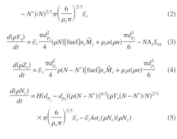
The equations below correspond to the extended model 共see Ref.关1兴 for the base line soot and oxidation models兲:
d共n兲 dt = a0关fuel兴e −Ta/T+ f共n兲 − g共n兲共N兲 − S ox ⬘ 共1兲 d共N兲 dt = a共n兲 − b共n兲共N兲 − H共dpl− dpZ兲共共N − N⬘兲兲 4/3共Y s共N − N⬘兲/N兲2/3
冉
6 s冊
2/3 v ¯r 共2兲 d共Ys兲 dt = v¯r dp i 2 4 共N兲关fuel兴ncM ¯ c+ sa共n兲 dp i 3 6 − NAsSox 共3兲 d共Zs兲 dt = v¯r dp i 2 4 共N − N⬘兲关fuel兴ncM ¯ c+ sa共n兲 dp i 3 6 共4兲 d共Nc兲 dt = H共dpz− dpl兲共共N − N⬘兲兲 4/3共Y s共N − N⬘兲/N兲2/3 ⫻冉
6 s冊
2/3 v ¯r− v¯r4c共Nc兲共Nc兲 共5兲Contributed by the Internal Combustion Engine Division of ASME for publication in the JOURNAL OFENGINEERING FORGASTURBINES ANDPOWER. Manuscript received April 30, 2007; final manuscript received February 15, 2008; published online August 22, 2008. Review conducted by Kalyan Annamalai. Paper presented at the 2006 Fall Conference of the ASME Internal Combustion Engine Division 共ICEF2006兲, Sacramento, CA, November 5–8, 2006.
Table 1 Kinetics in the soot model. For detailed
infor-mation, see Ref. †1‡. For ease, the basic kinetics from Ref. †3‡ on which this modeling is based is recalled in the
caption: d„N… / dt = a„n… − b„n…„N… and d„n… / dt
= a0†fuel‡exp„−Tan 0 / T… + F„n… − g0„n…„N… Ta 21,000 K a 105共⫺兲 f 100共⫺兲 g 10−15m3 b 8 ⫻ 10−14m3 a0 2.3⫻ 10−3Hz s 1900 kg/ m3 D0 1 nm
d共N⬘兲 dt = 2H共dpZ− dpl兲共共N − N⬘兲兲 4/3共Y s共N − N⬘兲/N⬘兲2/3 ⫻
冉
6 s冊
2/3 v ¯r+ v¯r共dc/2 + dp/2兲2共N − N⬘兲共Nc兲 共6兲 where f, g, a, and b are the parameters in Ref.关3兴 for Semenov-type equations; Tais the activation temperature of the fuelpyroly-sis step; sis the density of soot and Ysis its mass fraction; dp
iis
the inception diameter of soot from radicals; a0is the preexponen-tial factor estimating the rate of pyrolysis; 关fuel兴 is the molar concentration of the hydrocarbon共HC兲 fuel; nc is the number of
carbon atoms in the HC molecule; M¯cis the carbon molar weight; and AsSoxand Sox
⬘
are the oxidation terms. Details of these terms are provided in Ref.关1兴 and their values are quickly recalled in Table 1. The first equation is for the number density of active0 25 50 75 100 125 CA [Deg.] 0.0 5.0×10⁻⁹ 1.0×10⁻⁸ 1.5×10⁻⁸ 2.0×10⁻⁸ Soot Mass [kg] 0 % EGR, dp l = 30 nm 8 % EGR, dp l = 30 nm 0 % EGR, dp l = 0 nm (a) 0 25 50 75 100 125 CA [Deg.] 0.0 5.0×10¹⁰ 1.0×10¹¹ 1.5×10¹¹ Part icle Number 0 % EGR, dp l = 30 nm 8 % EGR, dp l = 30 nm 0 % EGR, dp l = 0 nm (b) 0 25 50 75 100 125 CA [Deg.] 0.0 1.0×10⁸ 2.0×10⁸ 3.0×10⁸ 4.0×10⁸ 5.0×10⁸ Number o f Precursor Particles 0 % EGR, dp l = 30 nm 8 % EGR, dp l = 30 nm (d) 0 25 50 75 100 125 CA [Deg.] 0 1×10⁹ 2×10⁹ 3×10⁹ 4×10⁹ 5×10⁹ 6×10⁹ 7×10⁹ C luster Number 0 % EGR, dp l= 30 nm 8 % EGR, dp l = 30 nm 0 % EGR, dp l = 0 nm (e) 0 25 50 75 100 125 CA [Deg.] 0 10 20 30 40 50 60 Primary Particle Diameter [nm] 0 % EGR, dpl= 30 nm 8 % EGR, dp l = 30 nm 0 % EGR, dp l = 0 nm (c) 0 25 50CA [Deg.]75 100 125 0 5 10 15 20 Number of Particles / Cluster 0.0 5.0×10¹⁰ 1.0×10¹¹ 1.5×10¹¹ 2.0×10¹¹ Number of Particles in C lusters < > (f)
Fig. 1 Soot formation history in the cylinder sector: „a… mass, „b… primary particle number, „c… root mean
cubic diameter, „d… precursor particle number, „e… cluster number, and „f… aggregated particles; line: 0%
EGR, dashed: 8% EGR, and dots: 0% EGR, no threshold diameter „dpl= 0…
10 20 30
Number of Particles / Cluster
0.0 5.0×10⁴ 1.0×10⁵ 1.5×10⁵ 2.0×10⁵ Count
Fig. 2 Distribution of cluster size in terms of particle number;
open 0% EGR, and shaded 8% EGR
radicals n 共fuel molecule pyrolysis兲. The second equation is for the soot primary particle population N. A third equation based on kinetic theory describes the change in mass Ys of the primary
particles through growth and coalescence. Evidence is reported in Ref.关4兴 through transmission electron microscopy 共TEM兲 imag-ing that agglomeration may happen very early in the cylinder. Hence, new terms extending the model to agglomeration are ex-pressed in the last three equations and the introduction of Heavi-side function in the number density equation, Eq.共2兲. The prin-ciple for the present development is the following. A subpopulation N
⬘
of N particles is considered agglomerating intoNc clusters. The remaining共N − N
⬘
兲 particles are still free. Each time two free particles collide, they may coalesce共last term of Eq. 共2兲兲 or stick and form a structure 共first term of Eq. 共5兲兲. The transition between coalescence and agglomeration is not obvious 关2兴. A sensible approach consists in saying that coalescence is no longer possible when the particle is too old, which means that it is solid and the surface is no longer active enough for growth such that it cannot be buried. Size might be a good indication of aging. However, oxidation and coalescence lead to a change in size, which is not related to chemical aging. Thus, a tracer is intro-duced. This tracer is a virtual soot mass fraction. It is based on free particles and surface growth only 共without oxidation or co-agulation兲. This is Eq. 共4兲. When the tracer-particle diameter dpZisbigger than a threshold diameter dp
l, coalescence is switched off
共last term of Eq. 共2兲兲 and agglomeration is switched on 共first term of Eqs. 共5兲 and 共6兲兲. These are the Heaviside functions. Each creation results in two initial particles per structure共first term of Eq.共6兲兲. Structures may collide with free particles 共second term of Eq.共6兲兲 and increase their particle number. They may also collide
with each other共second term of Eq. 共5兲兲 and form a single bigger cluster.
All collisions are assumed effective. They are based on basic kinetic theory to make the model simple and self-consistent. v¯ris the relative velocity between two particles in Brownian motion. Its square is thus equal to the sum of their respective quadratic mean velocities. For modeling, the cluster collision surface, a disk equivalent to the projected surface, is retained. The projected sur-face, is the sum of the projected surfaces of the primary particles, according to Ref.关5兴. This interesting discovery makes the model independent of the fractal parameters, which are acknowledged to
Fig. 3 „a… Primary particle location „EVO…. Left: density
num-ber isosurface, 2.3Ã 1014m−3; range „1.5Ã1013m−3, 3.3
à 1014m−3…. Right: diameter isosurface. Internal 20 nm. Exter-nal 30 nm. Range „0 nm, 42 nm…, „b… Cluster location „EVO….
Left: density number isosurface, 1.2Ã 1013m−3; range „1.5
à 1011m−3, 1.6à 1013m−3…. Right: particles per cluster
isosur-face 14; range „4, 17…. Note that the different sectors are the same computational sector representing different quantities.
(a)
(b)
(c)
Fig. 4 „a… Primary particle diameter field. Internal isosurface:
17.5 nm. External isosurface: 35 nm. „b… Cluster size „number of particles… field. Internal isosurface: 7. External isosurface:
16. „c… Cluster size „apparent diameter „Ref. †5‡…, dc… field.
vary with engine geometry, speed, and load. Thus, the projected surface/collision area is given by c= dc2/4 = N
⬘
/Ncdp2/4, whereN
⬘
/Nc is the number of particles per cluster. dc is the estimated diameter of the cluster and dpis the diameter of the primary par-ticle. Kinetic theory has limits for complicated structures like frac-tal aggregates. They may be animated by a complex movement not considered in the theory. Furthermore, their response to turbu-lent flow may be very different from small soot particles. Aggre-gation rate may thus be higher than predicted because of a non-representative evaluation of the relative velocity. Empirical approaches have pointed out this problem in typical engine flows 关6,7兴. This is the reason why comprehensive approaches based on kinetic theory, as in Ref.关8兴, are of limited utility here. Correc-tions to augment the Brownian collision rate are very empirical at the present time. It is furthermore hard to believe that they are adapted to the considered configuration. Hence, an arbitrary factor of 100 from the Brownian collision rate appearing in the last term of Eq.共6兲 has been used to enhance particle clustering in order to maintain simplicity in the model. Tests have demonstrated that change in this factor has marginal impact on soot prediction 共ex-cept, of course, cluster size兲 as it has no direct interaction with the soot mass growth. The chosen magnifying factor is arbitrary. Given limited knowledge of this process, it is believed that this qualitative approach is appropriate to highlight phenomena prior to any practical consideration and validation.The reader is referred to Ref.关1兴 for the computational frame-work, tools, and configuration.
Results and Discussion
An overview of the simulation results is provided in Fig. 1. Numerous observations may be made:共i兲 cooled exhaust gas re-circulation共EGR兲 increases soot emissions by enhancing both the particle number density and the particle size through a lower over-all temperature regarding soot combustion during the expansion stroke and a higher equivalence ratio due to the presence of a vitiated mixture. These are the known prediction capabilities for this kind of model关1兴; 共ii兲 pyrolysis of fuel into soot precursors is known to be dependent on both temperature and fuel. This is properly accounted for as the formation of soot precursors is slightly delayed and is smaller for the EGR case. This leads to a time delay before the soot forms in the combustion chamber. The lower temperature in the cylinder for the EGR case slightly re-duces the early formation of soot precursors. On the other hand, EGR leads to more soot precursors later in the expansion stroke; and共iii兲 the choice of a threshold diameter dplto turn coagulation
into agglomeration is of little importance in the chosen frame-work. This numerical artifact is due to the Brownian-based coagu-lation rate being too low, as discussed earlier. In addition to the fact that contemporary knowledge does not allow any solution for this issue, the extremely fast maturation of soot particles proposed 共and still debated兲 in literature 关2兴 may be explained, below.
EGR leads to a slightly smaller number of clusters being formed. This might be due to a reduced early collision frequency between free primary particles. This frequency is dependent on temperature. However, the number of particles per cluster is
Fig. 5 Sequence of formation of the soot. Left: cluster density number isosurface,
1 Ã 1013kg−1. Middle: soot particle density number isosurface, 1 Ã 1013kg−1. Right:
radical density number isosurface, 1 Ã 1013kg−1. Transparent isotemperature at
1500 K. „a… At radical appearance „CA= 9.6 ATDC…. „b… Close to end of injection „CA = 11.7 ATDC…. „c… At cluster appearance „CA= 18.0 ATDC…. „d… At radical disappearance „CA= 22.1 ATDC…. „e… At full evaporation „CA= 34.7 ATDC…. Note that the different sec-tors are the same computational sector representing different quantities.
larger. The dashed upper curve in Fig. 1共f兲 for the EGR case predicts that the number of particles in a cluster decreases and then increases. This trend occurs because the soot clusters that are recirculated into the combustion chamber due to cooled EGR are assumed to be fully mature with an average size of 100 particles. In contrast to the primary particle formation, the threshold di-ameter dp
lto switch from coagulation to agglomeration is visible
in cluster dynamics. In Fig. 1共f兲, the start of the cluster formation is revealed by the singularity on the left hand side of the graph. There are a few degrees crank angle between the 0 nm and 30 nm cases. This is negligible. Transition at 0 nm means that the par-ticles are never able to merge. On the other hand, transition at 30 nm involves more mature particles after a long process of sur-face growth and notable changes of sursur-face chemistry. This is consistent with the fast maturation of the primary particles, as discussed above, showing that the coagulation rate may be of limited importance. It is noted that the existence of soot particles at top dead center 共TDC兲 in this case is simply due to the
re--injection of the soot-containing exhaust gas 共without filter兲 into the intake.
For the following figures, isovalues have been chosen arbi-trarily to help the reader interpret the location of the species of interest. Furthermore, when a range of values is present in the caption, it is only for information purposes about the order of magnitude involved. This range is not represented in the picture. Distribution of the cluster size at exhaust valve opening共EVO兲 predicted by the numerical simulation is given in Fig. 2. The distribution shape is about the same for the non-EGR and EGR cases. The overall size is thus shifted to EGR as more particles tend to agglomerate.
Figure 3 gives comparative information about soot particles and clusters at the end of the expansion stroke. Consistent with our previous communication关1兴, bigger particles are found close to the cylinder wall and head. The proposed model is thus able to reproduce the trends experimentally observed关9,10兴. It allows one the interpretation that heat loss prevents the oxidation of primary particles. It has actually been shown that emission prediction in
Fig. 6 Sequence of formation of the soot. From left to right. Particle per cluster
isosurface= 16. Particle per cluster isosurface= 7. Primary particle size isosurface = 17.5 nm. Primary particle size isosurface= 35 nm. „a… Appearance of particles larger than 45 nm „CA= 9.6 ATDC…. „b… Close to the end of injection „CA= 13.8 ATDC…. „c… Appearance of clusters larger than seven particles „CA= 26.3 ATDC…. „d… End of evaporation „CA= 34.7 ATDC…. „e… Appearance of clusters larger than 16 particles „CA= 72.7 ATDC…. „f… CA= 93.3 ATDC. Note that the different sectors are the same computational sector representing different quantities.
the near-wall region is dramatically impacted by the surface tem-perature 关11兴. Oxidation is highly temperature dependent. The number density of particles is more important at the intermediate annular location in the cylinder, an area swept across by spray combustion. In regions close to the wall, where both particle di-ameter and number density are large, agglomeration is expected to be important. Figure 3共b兲 displays the presence of numerous ag-glomerated particles in this region. Both numerous clusters and numerous particles per cluster are found. Like the primary particle distribution, clusters tend to be larger close to the wall. This is consistent with the experiments as well. Growth, coagulation, and agglomeration are acknowledged to be simultaneous. It is thus admitted that some of the largest particles experimentally found may come from a more-or-less buried cluster, i.e., stuck particles are buried by surface growth.
A complete picture of the primary particle location with respect to size is provided in Fig. 4共a兲. A conical volume around the cylinder axis and embedding the bowl is filled with small par-ticles. A crown of large particles is located close to the corner between the top and the wall. Small particles are explained be-cause of oxidation. The interior of the cylinder volume is a well-mixed high-temperature zone throughout the combustion process. In contrast, the engine cooling system leads to heat losses at the boundaries. They are mainly located at the head and the wall. The oxidation of the soot is thus difficult in these regions. This leads to larger particles. The same formation history is exhibited by clus-ters, as shown in Figs. 4共b兲 and 4共c兲. Small clusters are present along the axis, consistent with the observations made about the results shown in Fig. 3. Numerous large particles have, however, agglomerated in a crown close to the top of the cylinder, accord-ing to the mechanism described previously. This provides the pic-ture of particle formation at the end of the expansion stroke and before entering the exhaust pipe. Further agglomeration is ex-pected to occur there.
A history of the soot formation is given in Fig. 5. The iso-1500 K defines a volume where the temperature is higher, as the transition criterion from ignition to combustion. In Fig. 5共a兲, radicals and soot particles are formed in rich, high-temperature zones. These zones are on the side of the spray and between the spray paths as swirl entrains a rich mixture fed with evaporating fuel. Over time, clouds of soot grow in the proximity of the spray, as shown in Fig. 5共b兲. Then, clusters begin to appear in the area where the density of soot particle is high, as shown in Fig. 5共c兲. This area is of an annular shape with a diameter roughly of the order of the bowl. The shape of this area is explained by the presence of evaporating spray, impacting close to the edge of the bowl and mixing with hot air. It is in this rich region where the
soot is formed. During the expansion stroke, this region is simply stretched in the direction of the downward motion of the piston. The result is the field observed in Figs. 3 and 4. Figure 6 displays another picture of the described phenomena. Particles of the soot are formed very early, as exhibited in Fig. 6共a兲. They easily reach a large size in the rich, high temperature zone in the vicinity of the spray, Fig. 6共b兲. Clusters appear later and slowly grow, Figs. 6共c兲–6共e兲. As mentioned before, they preferably appear and grow at an annular location that corresponds to a zone where numerous and large particles are found.
Acknowledgment
This research has been made possible by the funding received from the Government of Canada Program for Energy Research and Development共PERD/AFTER兲. The authors wish to thank Dr. S. C. Kong and Professor R. D. Reitz for providing the grid speci-fication of the engine geometry and parameters. Dr. William Wal-lace is gratefully acknowledged for his fruitful comments regard-ing the improvement of the manuscript.
References
关1兴 Boulanger, J., Liu, F., Neill, W. S., and Smallwood, G. J., 2005, “An Improved Soot Formation Model for 3-D Diesel Engine Simulations,” ASME J. Eng. Gas Turbines Power, 129, pp. 877–884.
关2兴 Frenklach, M., 2002, “Reaction Mechanism of Soot Formation in Flames,” Phys. Chem. Chem. Phys., 4, pp. 2028–2037.
关3兴 Tesner, P., Snegiriova, T., and Knorre, V., 1971, “Kinetics of Dispersed Carbon Formation,” Combust. Flame, 17, pp. 253–260.
关4兴 Su, D. S., Müller, J.-O., Jentoft, R. E., Rothe, D., Jacob, E., and Schlögl, R., 2004, “Fullerene-Like Soot From EUROIV Diesel Engine: Consequences for Catalytic Automotive Pollution Control,” Top. Catal., 30/31, pp. 241–245. 关5兴 Brasil, A. M., Farias, T. L., and Carvalho, M. G., 1999, “A Recipe for Image
Characterization of Fractal-Like Aggregates,” J. Aerosol Sci., 30, pp. 1379– 1389.
关6兴 Khan, I. M., Wang, C. H. T., and Langridge, B. E., 1971, “Coagulation and Combustion of Soot Particles in Diesel Engines,” Combust. Flame, 17, pp. 408–419.
关7兴 Smith, O. I., 1981, “Fundamentals of Soot Formation in Flames With Appli-cation to Diesel Engine Particulate Emissions,” Prog. Energy Combust. Sci.,
7, pp. 275–291.
关8兴 Kazakov, A., and Frenklach, M., 1998, “Dynamic Modeling of Soot Particle Coagulation and Aggregation: Implementation With the Method of Moments and Application to High-Pressure Laminar Premixed Flames,” Combust. Flame, 114, pp. 484–501.
关9兴 Shahad, H. A. K., 1989, “An Experimental Investigation of Soot Particle Size Inside the Combustion Chamber of a Diesel Engine,” Energy Convers. Man-age., 29, pp. 141–149.
关10兴 Leipertz, A., and Dankers, S., 2003, “Characterization of Nano-Particles Using Laser-Induced Incandescence,” Part. Part. Syst. Charact., 20, pp. 81–93. 关11兴 Wiedenhoefer, J. F., and Reitz, R. D., 2000, “Modeling the Effect of EGR and
Multiple Injection Schemes on I.C. Engine Component Temperatures,” Numer. Heat Transfer, Part A, 37, pp. 673–694.