HAL Id: tel-01522803
https://tel.archives-ouvertes.fr/tel-01522803
Submitted on 15 May 2017HAL is a multi-disciplinary open access archive for the deposit and dissemination of sci-entific research documents, whether they are pub-lished or not. The documents may come from teaching and research institutions in France or abroad, or from public or private research centers.
L’archive ouverte pluridisciplinaire HAL, est destinée au dépôt et à la diffusion de documents scientifiques de niveau recherche, publiés ou non, émanant des établissements d’enseignement et de recherche français ou étrangers, des laboratoires publics ou privés.
SuperKEKB
Dima El Khechen
To cite this version:
Dima El Khechen. Fast Luminosity Monitoring Using Diamond Sensors for SuperKEKB. High Energy Physics - Experiment [hep-ex]. Université Paris-Saclay, 2016. English. �NNT : 2016SACLS565�. �tel-01522803�
NNT : 2016SACLS565
T
HÈSE
DE
DOCTORAT
DE
L’U
NIVERSITÉ
P
ARIS
-S
ACLAY
PRÉPARÉE
À
L'U
NIVERSITÉ
P
ARIS
-S
UD
E
COLED
OCTORALEN° 576
Particules, Hadrons, Energie, Noyau,
Instrumentation, Imagerie, Cosmos et Simulation
(PHENIICS)
Spécialité : Physique des accélérateurs
Par
Mlle Dima EL KHECHEN
Fast Luminosity Monitoring Using Diamond Sensors For
SuperKEKB
Thèse présentée et soutenue au LAL, le 16 Décembre 2016 :
Composition du Jury :
M. Stocchi Achille Directeur, LAL, Orsay Président
M. Baudot Jérome Professeur, Université de Strasbourg Rapporteur
M. De Conto Jean-Marie Professeur, Université de Grenoble Rapporteur M. Funakoshi Yoshihiro Professeur, KEK/Sokendai university Examinateur M. Uehara Sadaharu Professeur Associé, KEK/Sokendai university Examinateur Mme Boscolo Manuela Physicienne, INFN/Frascati Examinatrice
M. Bambade Philip Directeur de recherche, LAL, Orsay Directeur de thèse
Mme Rimbault Cécile Chargée de recherche, LAL, Orsay Co-encadrante de thèse
Titre: Monitorage rapide de la luminosité au moyen de capteurs diamant pour SuperKEKB
Mots clés: monitorage rapide de la luminosité, capteur diamant, Bhabha radiatif, collisionneur à très
haute luminosité.
Résumé: SuperKEKB est un collisionneur à
très haute luminosité construit pour l’expérience Belle II, constitué d’ un anneau de basse énergie (LER) transportant des positrons de 4 GeV et d’un anneau de haute énergie (HER) où circulent des électrons de 7 GeV. Sa mise en service -ou commissioning- se déroulera en trois phases : La phase 1, durant laquelle des faisceaux circulent sans être focalisés au point de collision, a pour but de nettoyer la chambre à vide du gaz résiduel. La seconde phase, où le détecteur Belle II sera en partie installé, permettra le réglage du système de focalisation finale des faisceaux, jusqu’à atteindre une luminosité de 1034 cm-2 s-1 . La troisième phase
correspondra au démarrage de l’expérience Belle II avec une luminosité visée de 1035 cm-2s1
à 8×1035 cm-2 s-1.
Dans ce cadre, ma thèse porte sur la conception et la mise en place d’un système permettant le monitorage rapide de la luminosité, système nécessaire pour pouvoir corriger en temps réel les instabilités des faisceaux et ainsi maintenir une luminosité optimale. Afin d’atteindre la haute précision relative souhaitée, de l’ordre de 10-3 en 1 ms, la mesure sera basée sur le taux de
comptage des particules issues de la diffusion Bhabha radiative à angle nul, processus bien connu et dont la section efficace est importante. Ces particules seront détectées au moyen d’un capteur en diamant, matériau résistant aux radiations et permettant une acquisition très rapide du signal, situé à l’extérieur de la chambre à vide et en aval du point d’interaction.
La première partie de cette thèse est consacrée à la recherche des localisations optimales pour le positionnement des capteurs diamants dans chacun des deux anneaux. Au moyen de simulations détaillées, nous avons étudié la dynamique des particules Bhabha lors de leur transport dans les anneaux ainsi que leur interaction avec la matière de la chambre à vide. Ces études ont permis d’ une part d’ identifier un emplacement à 11.9m dans le LER et un autre à 30 m dans le HER, et d’autre part de redéfinir pour l’une d’ entre elle la géométrie locale du tube à vide.
La seconde partie, plus expérimentale, s’articule autour de la première phase du commissioning de SuperKEKB et des mesures réalisées au moyen des capteurs diamants que nous avons installés. Dans un premier temps, une étude détaillée des processus de perte single beam (Bremsstrahlung, effet Touschek, diffusion coulombienne) a été réalisée pour le LER en fonction des paramètres du faisceau et du collisionneur (courant, pression, taille transverse des faisceaux). Dans un deuxième temps les résultats de cette étude ont été comparés aux données que nous avons prises de février à juin 2016. Nous avons pu mettre en évidence un bon accord qualitatif et quantitatif entre nos simulations et nos mesures. Cela nous a permis d’estimer que le niveau de bruit de fond attendu dans le cadre des mesures pour le monitorage de la luminosité sera de plus de deux ordres de grandeurs inférieurs au taux du processus Bhabha radiatif à angle nul.
Keywords: fast luminosity monitoring, diamond sensors, radiative Bhabha scattering, very high
luminosity collider.
Abstract: SuperKEKB is a very high
luminosity collider dedicated to the Belle II experiment, it consists of a Low Energy Ring (LER) of 4 GeV positrons and a High Energy Ring (HER) of 7 GeV electrons. The commissioning of this machine is split into three phases: phase 1 (single-beam phase) is dedicated to vacuum scrubbing, where beams circulate without focusing at the collision point. Phase 2, for which the major part of the Belle II detector will be installed, will enable the tuning of the final focus system to achieve a luminosity of 1034 cm-2 s-1 . During phase 3,
Belle II physics runs will start with an aimed luminosity up to 8×1035 cm-2 s-1 .
In this context, the aim of my thesis is to develop and install a fast luminosity monitoring system, which is required for online correction of beam instabilities and maintenance of optimal luminosity. To reach the aimed relative precision of 10-3 in 1 ms, the
measurement will be based on the radiative Bhabha process at zero photon scattering angle, whose cross-section is large and well-known. These particles will be detected using diamond sensors, resistant to radiation and enabling very fast signal acquisition, to be placed outside of the beam-pipe and downstream of the interaction point.
The first part of this work is dedicated to the investigation of the best locations for the diamond sensor positioning in both rings. Using detailed simulations, we studied the dynamics of Bhabha particles during their tracking in the rings and their interaction with the beam pipe material. This led to the identification of two positions, at 11.9 m in LER and at 30 m in HER, and to considering a new geometry for the vacuum pipe in the LER.
The second part is related to the phase 1 of the SuperKEKB commissioning and concerns the measurements performed with the diamond sensors that were installed. Single beam loss processes (Bremsstrahlung, Touschek, beam-gas Coulomb scattering) were studied in detail with respect to the LER beam and ring parameters (current, pressure, transverse beam sizes). The results of this study were then compared to the data collected from February to June 2016. We found good qualitative and quantitative agreement between our simulations and measurements. From this we could estimate that the level of background to be expected during luminosity monitoring will be two orders of magnitude smaller than the rate of the radiative Bhabha scattering signal.
Université Paris-Saclay
Espace Technologique / Immeuble Discovery
Monitorage rapide de la luminosité au moyen de capteurs diamant pour
SuperKEKB
Introduction:
SuperKEKB est un collisionneur à très haute luminosité construit pour l’expérience Belle II, constitué d’un anneau de basse énergie (LER) transportant des positrons de 4 GeV et d’un anneau de haute énergie (HER) où circulent des électrons de 7 GeV. Sa mise en service -ou commissioning-se déroulera en trois phacommissioning-ses : La phacommissioning-se 1, durant laquelle des faisceaux circulent sans être focalisés au point de collision, a pour but de nettoyer la chambre à vide du gaz résiduel. La seconde phase, où le détecteur Belle II sera en partie installé, permettra le réglage du système de focalisation finale des faisceaux, jusqu’à atteindre une luminosité de 1034 cm-2s-1. La troisième phase correspondra au
démarrage de l’expérience Belle II avec une luminosité visée de 1035 cm-2 s-1 à 8×1035 cm-2 s-1.
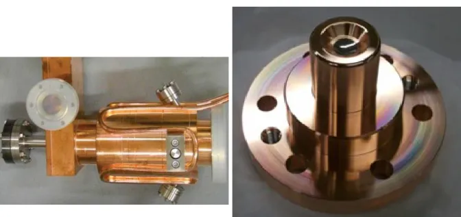
SuperKEKB a adopté le schéma de collision "nano-beam"qui implique une focalisation très forte au point d'interaction (IP) pour obtenir des faisceaux de très petites tailles verticales. Parce que la taille des faisceaux est de quelques dizaines de nanomètres seulement, la luminosité est très sensible à la stabilité des éléments de focalisation finale dont les vibrations provoquent un mouvement d'orbite qui pourrait être 4 ou 5 fois plus grand que la taille verticale des faisceaux. De telles vibrations provoquent des oscillations verticales du faisceau à l'IP à des fréquences allant jusqu'à 100 Hz, alors que les mouvements horizontaux sont attendus à quelques Hz. Les différences d'orbite des deux faisceaux à l'IP conduisent à une dégradation de la luminosité. Pour parer à cela, un système de «dithering» est dédié à la rétroaction (feedback) horizontale consistant principalement en un lock-in amplificateur, des bobines de dithering et un moniteur rapide de luminosité. Le moniteur rapide de luminosité se compose de deux différents détecteurs, des capteurs monocristallin en diamant (sCVD) utilisés par notre groupe au LAL, et les détecteurs Cherenkov et scintillateur en coïncidence utilisés par groupe Zero Degree Luminosity Monitor (ZDLM) au KEK. Le moniteur de luminosité mesure la luminosité relative à 1 KHz et les corrections de feedback sont appliquées à l'échelle d'une seconde. Les deux détecteurs sont placés l'un à côté de l'autre, juste à l'extérieur du tube à vide dans les deux anneaux de SuperKEKB, et mesureront le signal du processus de Bhabha radiatif à angle nul. La précision relative requise sur la luminosité en phase 3 est de 10-3, avec moins
de 1% de contamination par des bruits de fond.
Les positions des capteurs dans le LER et le HER:
Le choix des emplacements des capteurs dans chacun des anneaux a nécessité plusieurs étapes, de la génération des particules Bhabha et de leur dynamique (au moyen de GUINEAPIG++, outil de modélisation des interaction faisceau-faisceau) à leur transport dans les anneaux (en utilisant SAD), jusqu'à plusieurs dizaines de mètres en aval de l'IP. Les résultats ont montré que le meilleur emplacement pour positionner nos capteurs dans le LER se situe dans une section droite (drift) à 11.9m en aval de l'IP, le taux de Bhabha perdus y étant suffisant (potentiellement 4.7% de la section efficace totale) ainsi que l'espace libre disponible. L'interaction des particules perdues avec la matière de la chambre à vide a ensuite été simulé au moyen de GEANT4, pour pouvoir étudier et estimer le signal reçu par les capteur diamant. Dans le drift à 11.9m, la chambre à vide est un tube cylindrique de 3 mètres de long et de 6 mm d'épaisseur. Les positrons issus du processus Bhabha sortent de la chambre à vide avec un très petit angle (5 mrad), traversant 1.2 m de matériau, ce qui conduit à une grande absorption de la gerbe électromagnétique à la sortie du tube à vide et n'induit qu'un très faible signal dans le diamant.
Pour augmenter la gerbe électromagnétique et donc le signal dans les capteurs, l'inclusion d'une fenêtre à 45o a été suggérée par les physiciens de KEK en charge du vide dans la machine. Les
peut provoquer des champs de sillage (wakefields) et entraîner des instabilités du faisceau. En conséquence, différents types de matériaux (Aluminium, Berilium, Titane ,Cuivre) ont été simulés avec GEANT4 à différentes épaisseurs. Les simulations ont révélé que la fenêtre donne la meilleure précision parmi tous les autres modèles, et les simulations de wakefields effectuées au KEK ont montré des instabilités suffisamment faibles. Il a donc été décidé d'installer la fenêtre dans le drift à 11.9 mètres dans le LER pour la phase 2.
Pour augmenter la gamme de luminosités sur lesquelles des mesures précises peuvent être effectuées, nous souhaitons également utiliser des capteurs diamant (DS) dans le HER. De la même manière que pour les positrons dans le LER, les électrons issus du processus Bhabha ont été générés et leur transport dans le HER simulés jusqu'à 70m. Contrairement à ce qui se passe dans le LER, la déflection des positrons Bhabha le long du HER n'est linéaire avec leur énergie. Les particules perdues sont distribuées de manières stochastiques de part et d'autres de la chambre à vide, et quelque soit le positionnement des capteurs, la fraction des électrons Bhabha interceptée dans le DS est trop faible pour atteindre la précision visée.
Une autre méthode consiste à mesurer le signal des photons issus du processus Bhabha considéré avec le DS dans le HER. Les photons Bhabha sont produits à l'IP à très petits angles, de l'ordre de 0.4 mrad. Du fait de leur neutralité électrique, ils ne sont pas déviés par les champs magnétiques des éléments optiques, et sortent à un endroit précis de l'anneau.
Des simulations détaillées sont actuellement effectuées dans le groupe LAL en considérant l'optique du HER et la géométrie de la chambre à vide. L'analyse préliminaire montre que le spot des photons atteint le front de l'antichambre au milieu d'un sextupôle (à 27.4 mètres en aval de l'IP) à un angle moyen de 5.9 mrad. En raison de leur distribution transverse initiale, le spot projeté des photons sur la chambre s'étalent sur 2 à 3 mètres de part et d'autre du point de sortie nominal situé à 27.4m en aval de l'IP. L'espace libre le plus proche de ce point pour y placer les moniteurs de luminosité se situe à 30m en aval de l'IP. Comme les études en cours le montrent, une fraction importante de la section efficace de Bhabha radiatif peut être détectée à cet endroit.
Les capteurs diamant
Le diamant possède de nombreuses propriétés intéressantes qui lui permettent d'être l'un des meilleurs candidats aux détecteurs de rayonnement à l'état solide. Il a la plus grande conductivité thermique parmi les matériaux solides en plus d'une isolation électrique élevée. Le diamant a une énergie de liaison très élevée qui le rend très insensible aux rayonnements. De plus, le diamant se caractérise par un large écart de bande qui réduit le courant de fuite et diminue ainsi le bruit.
De plus, le diamant dispose de fortes mobilités des électrons et des trous, ce qui se traduit par une collecte rapide des charges et donc par des signaux rapides, dans la gamme de quelques ns. La largeur du signal dépend de l'épaisseur du diamant, par exemple une largeur de signal de 4-5 ns correspond à un diamant de 500 μm d'épaisseur. L'énergie minimale nécessaire pour créer une paire électron-trou dans le diamant est de 13 eV. Un MIP (Minimum Ionizing Particle) créé 36 paires électron-trou par μm dans le diamant. Un MIP est une particule chargée avec un taux de perte d'énergie proche du minimum, et l'énergie d'un électron au MIP est d'environ 1.6 MeV. Le champ électrique de polarisation que nous appliquons pour collecter les paires électron-trou est E = 0.8 V/μm. Normalement, nous pouvons appliquer une tension de polarisation jusqu'à 1 V/μm, cependant, grâce à la très bonne qualité du diamant, l'efficacité de la collecte de charge atteint 100% avant cette tension de polarisation (à ≈ 0,2 V/μm). Pour la sécurité, nous choisissons d'appliquer une tension un peu inférieure à 1 V/μm, soit 0,8 V/μm. Un désavantage du capteur diamant est la
difficulté d'avoir une grande zone active, ce qui restreint nos mesures à une partie de la gerbe dans le cas d'une chambre à vide sans fenêtre.
Le fonctionnement et la lecture du DS sont simples. Une particule chargée traverse le DS créant des paires électron-trou en fonction de son énergie. En appliquant une haute tension aux électrodes du diamant, des charges opposées dérivent vers les électrodes. Le signal de sortie résultant de la chute de tension est lue par un oscilloscope. Dans le cas d'un petit signal, par exemple une faible intensité des particules incidentes et/ou des DS très minces , l'amplification du signal est nécessaire. Le dépôt d'énergie dans le DS suit une distribution Landau.
Pour mieux comprendre le comportement du signal dans le DS, nous avons effectué des tests en salle blanche en utilisant des sources radioactives. La configuration expérimentale se compose de la source β 90Sr, un DS de 140 μm (qui sera utilisé en phase 3 de SuperKEKB), un amplificateur de
charge de CIVIDEC dont la constante de temps de mise en forme est d'environ 10 ns, un scintillateur, une alimentation de basse tension de 12V pour l'amplificateur de charge, une alimentation haute tension pour le DS et un oscilloscope pour lire le signal. Étant donné que l'amplificateur de charge est unipolaire, la haute tension (-100 V) sur le DS est appliquée pour polariser négativement et pour obtenir des impulsions négatives à sa sortie.
Un support mécanique spécial a été préparé pour les tests. Le capteur de 140 μm est connecté à l'amplificateur de charge alimenté avec 12 V et les deux sont posés sur le banc central du support mécanique. Sur la partie supérieure, il existe une ouverture spéciale pour les électrons émis par la source radioactive pour atteindre directement la surface 4x4mm2 du diamant situé en dessous. Juste
au-dessous du diamant, un scintillateur est utilisé pour le déclenchement, afin de collecter uniquement les signaux des MIP, c'est-à-dire que le MIP traversera le diamant en déposant une partie de son énergie, sans être absorbé, puis atteindra le scintillateur et donnera un signal de déclenchement. Les données sont collectées pendant généralement 10 heures puis analysées. En plus de la reconstruction de la distribution de Landau du maximum de signal pour les diamants de deux épaisseurs (140m et 500m), nous avons vérifié que la position en temps du MPV (Most Probable Value) du signal ne se déplace pas significativement et ne dépend pas de l'amplitude du signal. Ceci est très important parce que dans nos mesures, nous échantillonnons à 1 GSPS (Giga Sample Per Second), ce qui signifie chaque 1 ns.
La phase 1 du commissioning de SuperKEKB
Lors de la première phase du commissioning du SuperKEKB, où la machine a fonctionné sans système de focalisation finale et sans le détecteur Belle-II, les faisceaux de positrons et d'électrons ont été produits avec succès, accélérés, injectés et stockés dans les anneaux principaux (LER et HER) de SuperKEKB.
Les objectifs principaux de cette phase étaient de démarrer chaque système de hardware de la machine (linac d'injection, système magnétique, système RF dans les deux anneaux, système de vide, ...) et définir un logiciel d'opérations du faisceau basé sur SAD. Au cours de cette période de mise en service, le lavage sous vide a été effectué dans les deux anneaux à différents courants, à partir de courants très faibles (30 mA) jusqu'à des courants élevés (1 A), afin de nettoyer les
chambres à vide des gaz résiduels. Le gaz résiduel provoque une perte de faisceau due à la diffusion des particules du faisceau sur les molécules de gaz, soit par Bremsstrahlung (perte d'énergie de la particule en émettant un photon), soit par diffusion Coulombienne (diffusion à grand angle). Le lavage sous vide s'effectue par la circulation des faisceaux dans chaque anneau: le champ électromagnétique des faisceaux interagi avec la matière du tube à vide et en arrache des molécules qui sont ensuite extraites de la chambre à vide par un système de pompes NEG. Le lavage sous vide à des courants élevés (500 mA à 1 A) a été demandé par la collaboration Belle II pour protéger le
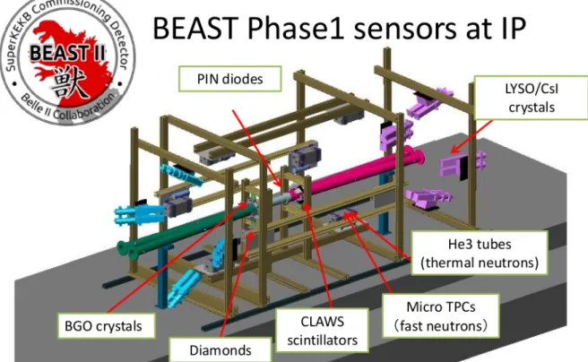
Des études spéciales dans les deux anneaux ont été menées dans le cadre de BEAST II, telles que la mesure des bruits de fond issus de la diffusion Touschek, de ceux résultant de l'interaction du faisceau avec le gaz résiduel, des bruits d'injection et les études de collimation. L'étude des Touschek a été réalisée en modifiant la taille verticale des faisceaux, par l'induction d'un couplage entre les émittances horizontale et verticale. Les études du bruit de fond faisceau-gaz ont été effectuées en induisant des «bumps» de vide en amont de l'IP dans des sections particulières des anneaux. Ces «bumps» de vide sont le résultat de la désactivation de quelques pompes NEG à des emplacements sélectionnés. Pour étudier l'effet des collimateurs sur les pertes du faisceau, les paramètres de certains collimateurs (largeur) ont été modifié.
Un autre objectif essentiel de la phase 1 du commissioning était de comprendre les problèmes qui peuvent survenir lors de l'opération à courant élevé (le blow up de la taille verticale du faisceau, l'avortement du faisceau, le comportement non linéaire de la pression avec le courant). Le groupe de mise en service de SuperKEKB a également de nombreuses études optiques.
Notre projet en phase 1:
Pour obtenir la précision visée sur les mesures de luminosité, nos capteurs doivent être placés dans des endroits où la contamination par des bruits de fond émanant du faisceau (bruits de fond single-beam) est minime (<1%). Par conséquent, l'étude des processus de perte single-beam est également importante pour notre projet.
Les capteurs diamant ont été installés aux emplacements que nous avons déterminés et nous ont permis durant la phase 1, l'acquisition de données permettant l'étude de plusieurs aspects:
• Vérifier le fonctionnement de nos capteurs et l'installation globale (électronique et mécanique) dans des conditions de fonctionnement de la machine.
• Mesurer les bruits de fond aux emplacements des capteurs choisis pour les mesures de luminosité dans les deux anneaux.
• Comparer les données à la simulation, et ainsi vérifier la fiabilité de nos simulations pour la phase 2.
• Une fois la fiabilité de la simulation confirmée, nous pouvons extrapoler nos simulations de bruits de fond à la phase 2 et estimer les fractions de signal de pertes single-beam et du processus de Bhabha radiatif dans nos capteurs.
Les bruits de fonds de Bremsstrahlung, la diffusion Touschek et la diffusion Coulombienne inélastique sont considérés comme des pertes single-beam, ils sont générés dans tout de l'anneau en raison de la diffusion des particules du faisceau sur le gaz résiduel ou de la diffusion des particules du faisceau les unes sur les autres. En plus d'être perdues à l'intérieur de la région d'interaction (IR) et d'engendrer des bruits de fond dans le détecteur, les particules provenant de pertes single-beam sont également perdues dans les anneaux, réduisant ainsi après un certain temps l'intensité et la qualité du faisceau. Dans des anneaux tels que SuperKEKB et en raison des courants très élevés et de leur très petites tailles, les faisceaux ont donc des durées de vie relativement courtes de l'ordre de 10 minutes. Les processus principaux déterminant la durée de vie des faisceaux sont l'effet Touschek et la diffusion Bhabha radiative à angle zéro à l'IP. Les faisceaux devraient donc être continuellement réinjectés pour maintenir leur intensité et donc maintenir une haute luminosité. Au cours de la phase 1 du commissioning de SuperKEKB, sans collision, les pertes principales étaient le Bremsstrahlung, la diffusion Touschek et la diffusion Coulombienne.
La diffusion Bremsstrahlung et les pertes résultantes sont proportionnelles au courant du faisceau et à la pression du gaz résiduel dans la chambre à vide. Pour l'effet Touschek, les pertes sont proportionnelles au carré du courant du faisceau et à l'inverse de la taille du faisceau. Comme pour Bremsstrahlung, la diffusion Coulombienne et les pertes résultantes sont proportionnelles au courant de faisceau et au niveau de vide.
Une version de SAD, écrite au KEK, a été utilisée pour simuler les pertes single-beam dans le LER. Les points de diffusion dans la version standard du code sont à l'entrée des quadrupôles, à l'exception des quadrupôles de focalisation finale pour les phases 2 et 3 et quelques aimants de courbure verticaux spéciaux . Le point d'observation est à l'entrée de chaque élément. Ainsi simulé, le spectre d'énergie des positrons Bremsstrahlung perdus dans le drift à 11.9 m, est discontinu et donc non physique. La raison de cette discontinuité est une résolution insuffisante des points de diffusion, qui ne permet pas d'obtenir une valeur correcte du taux de perte dans le drift.
Des modifications ont été apportées au code initial pour améliorer sa résolution, en ajoutant des points de diffusion à tous les éléments optiques et, pour les éléments longs, tels que les drifts et les aimants de courbure, en les découpant en tranches de longueurs égales. La diffusion des positons a ensuite été considérée à l'entrée de chaque tranche. Les aimants de courbure ont été découpés en petits tranches de ≈ 15 cm chacun, en gardant le même angle global de l'élément d'origine et les drifts ont été découpés en tranches de 10 cm chacune, de 50 mètres en amont à 13 mètres en aval de l'IP. De cette façon, nous avons récupéré tout le spectre d'énergie des positrons de Bremsstrahlung perdus dans le drift et obtenu une meilleure résolution sur les positions de diffusion. À l'aide de cette technique, le taux de perte obtenu dans le drift a été saturé tout en conservant le taux de perte dans l'ensemble de l'anneau: lorsque l'on augmente le nombre de positions de diffusion, nous augmentons la perte localement dans le drift alors que la perte totale globale dans toute l'anneau reste compatible dans les statistiques les erreurs.
Cette technique a ensuite été utilisée pour simuler et calculer les taux de pertes des diffusion de Bremsstrahlung, Touschek et Coulomb dans le drift, pour des pressions de vide, des courants et des tailles verticaux du faisceau différents. GEANT4 a été utilisé pour étudier les signaux de ces pertes dans le DS.
Pour pouvoir mesurer les pertes single-beam en phase 1, une installation expérimentale complète a été préparée au LAL et installée sur les deux anneaux de SuperKEKB, comprenant les supports mécaniques, les capteurs diamant et le système d'acquisition du signal.
Les supports mécaniques se composent de piliers dans chaque anneau. Chaque pilier prend en charge une plaque mobile avec deux capteurs diamant connectés chacun à un amplificateur de charge CIVIDEC et une plaque fixe avec les moniteurs ZDLM. La plaque mobile est associée à un moteur commandé à distance pour scanner dans la direction verticale sur une plage de 2.5 cm. Dans le HER, le pilier est installé à 30 mètres en aval de l'IP et les capteurs sont en face de l'antichambre dans le drift. Le pilier dans le LER est installé à 11.9 mètres en aval de l'IP et les capteurs sont en face à un tube de vide cylindrique normal dans le drift. En tout quatre capteurs diamant de 500 m ont donc été installés pour la phase 1 du commissioning.
Deux procédures d'acquisition de signaux ont été implémentées, soit par des enregistrements continus de 10 ms pouvant être traités à la volée toutes les 5-6 secondes soit jusqu'à une cinquantaine d'enregistrements de 410 ms dont le traitement a lieu en différé et dure quelques heures. Les données brutes acquises par un oscilloscope Keysight ont ensuite été converties en fichiers ".mat" et traitées avec MATLAB. Les fonctions de traitement ont été construites pour rechercher les formes d'onde des signaux des DS. Une fois les formes d'onde définies, les maxima
paramètres de la machine (comme le courant, la pression, la taille du faisceau, l'heure ...) et nous avons fusionné les données du DS avec les données EPICS après chaque acquisition.
Pendant la phase 1 du commissioning, nous avons pris des données principalement pendant les phases de nettoyage sous vide dans les deux anneaux et pendant des études de bumps de vide et les variations de la taille du faisceau dans le LER.
Les données prises pendant des bumps de vide ont été utilisées pour calculer la fraction des pertes liées au Bremsstrahlung dans des sections où les bumps ont été effectués et pour les comparer à des simulations. Les comparaisons ont montré que les données correspondent aux simulations au erreurs statistiques près.
Une étude de Touschek a été lors de l'augmentation de la taille verticale du faisceau. Les données ont été collectées pour six courants de faisceau différents dans le LER, I = 180, 360, 540, 720, 900 et 1000 mA et avec cinq taille de faisceau à chaque fois. Leur analyse a permis d'extraire les contributions de Bremsstrahlung et de Touschek. L'ajustement des pertes dans le diamant en fonction de l'inverse de la taille vertical du faisceau (σy-1) permet de séparer les deux contributions
de la manière suivante. Pour σy-1 proche de zéro, ce qui signifie que σy est très important, les pertes
de Touschek devraient disparaître et donc toutes les pertes dans le DS devraient être issues du Bremsstrahlung.
Les pertes de Bremsstrahlung extraites des ajustements ont été comparées aux simulations en fonction du produit de la pression de vide et du courant du faisceau. Les résultats ont montré que les données sont toujours supérieures d'un facteur à ceux prédits par la simulation. Ce facteur s'explique par le fait que la valeur de la pression mesurée par le CCG (Cold Cathode Gauge) devrait être multipliée par un facteur 3 pour représenter correctement la pression réelle de CO au centre de la chambre à vide.
Les pertes de Touschek extraites des ajustements ont également été comparées aux simulations. Nous observons un facteur de simulation/données = 1.7 ± 0.37. Nous avons étudié les raisons possibles de cette écart, et exclu des erreurs possibles concernant l'estimation des tailles longitudinale et verticale du faisceau, cohérente avec la valeur estimée à l'aide de la modélisation basée sur les mesures des fonctions optiques dans le LER. Une raison plausible pourrait être l'emittance horizontal, mais malheureusement il n'existe pas de mesures fiables de la taille horizontale du faisceau à SuperKEKB pour vérifier cette hypothèse. Nous ne pouvons pas non plus exclure complètement qu'une partie de cet écart vient de la simulation elle-même.
Le bon accord qualitatif et quantitatif entre nos simulations et les mesures nous a permis d'estimer le niveau de bruit de fond dans le DS pour la phase 2. Les estimations ont montré que le niveau de bruit de fond résultant des pertes d'un seul faisceau devrait être d'environ deux ordres de grandeur inférieur au taux du signal de Bhabha radiatif pour la phase 2. Cela satisfait les conditions spécifiées pour obtenir une haute précision relative sur la mesure de luminosité.
Conclusion:
Le travail de ma thèse a été utile pour trouver les meilleurs positions pour les moniteurs de luminosité dans les deux anneaux de SuperKEKB afin d'atteindre la précision visée sur la mesure de la luminosité. En outre, les simulations effectuées pour les pertes single-beam sont cohérentes avec les données prises au cours de la phase 1, ce qui nous a permis d'estimer le rapport entre le signal et
To my parents and siblings first …
And to every marginalized and oppressed person in this world !
للووأ يتوخإو يبأو يموأ ىلإ
Acknowledgements
I am honored to have been surrounded by great people during the three years of my PhD thesis work. It is difficult to mention all what they did for me in a short paragraph but I will never forget their direct or indirect contributions to my success.
Many thanks to the LAL director, Achille Stocchi, for hosting me almost 3 years and a half and for giving me the chance to work on this very interesting project. I would like as well to deeply thank the referees Jerome Baudot and Jean Marie De Conto for reading my thesis report and for giving nice comments on my work. Many thanks to Yoshihiro Funakoshi, Uehara Sadaharu and Manuela Boscolo for being the members of my thesis committee.
I would like to enormously thank my supervisors Philip Bambade and Cécile Rimbault for every single advice and for every information, discussion and support they gave me. I thank them for believing in me and my work and for their trust. Thank you for giving me the chance to participate on very important conferences and summer schools and thus acquiring a lot of experience in life. Many thanks to every person in our group who without their help in every manner, I couldn't have achieved what I have today. Thanks to Didier Jehanno, Viacheslav Kubytskyi, Yann Peinaud, Patrick Cornebise, Alex Blin and Frederic Bogard.
Part of this work has been funded by the P2IO LabEx (ANR-10-LABX-0038) in the framework “Investissements d’Avenir” (ANR-11-IDEX-0003-01) managed by the French National Research Agency (ANR), so many thanks to P2IO, as well many thanks to the Ecole doctorale PHENIICS for funding the other part, many thanks to Fabien Cavalier and Elias Khan.
Many thanks as well to all the people of the administrative service at LAL for helping me in all the administrative issues related to my thesis.
I will not forget the great support I got from Japanese Scientists, I would like to enormously thank Funakoshi san for giving me the great chance as a student to participate on the SuperKEKB commissioning and for letting me participate on operation shifts, as well for the very interesting discussions and for replying on all my questions. Thank you for believing in my abilities and inviting me to return to KEK to work on SuperKEKB, I believe I will always be in your debt. Many thanks to Uehara san for the nice collaboration and for the very interesting discussions. Many thanks to Ohnishi san for your code and for your enormous help. Sincere thanks to Iida san, Muira san, Ikeda san, Flannagan san, Masuzawa san and Koiso san.
In addition, I would like to thank every single person in the accelerator department for the nice moments we shared in the lab. Special thanks to Robert Chehab, Walid Kaabi, Hayg Guler, Cynthia Vallerand, Iryna Chaikovska, Mathilde Court, Mohamed El Khaldi, Cristelle Bruni, Sophie Chancé, Nicolas Delerue, Noureddine El Kamchi and Jean-Noel Cayla. Special thanks also to Marica Biagini for all the nice moments and for the physics and “non-physics” discussions.
Very special thanks to Catherine Bourge for being the big sister in everything and for supporting me during every nostalgic moment during more than 4 years. Thanks to Dominique Bony for the nice lunch moments together as well.
thanks to my teachers at “Asaad Abboud school”. Many thanks as well to my teachers at “Sohmor high school”.
Far from the office and the laboratory, special people were surrounding me and giving me a positive energy everyday to start. I cannot forget the memories we shared, the laughters which filled our small houses and the dances and “dabki” we performed which brought joy to my heart. Special, kind and lovely thanks to Fatima Al Reda, Marwa Zaarour, Marwa Koumaiha, Zeinab Koumaiha, Mohammad Tarhini, Mohamad Ayoub, Elie Saikaly, Mostafa Al Reda and Mayla Salman.
Infinite thanks to the one who considered me and still considering me as his daughter, for the one who taught me a lot of valuable things in life, who guided me while far from all the people I love, thank you Tokio Ohska, thank you my Godfather, I love you. Sweet thanks as well to my Classical singing teacher, for the lovely Keiko Nishimura.
For the people who were my family in Japan and will always be, thank you for being you and for every moment we spent together and for every support. Thank you Umberto Tamponi, Monica Frattari, Maryam Salihi, Hulya Hatmacan, Manca Mrvar, Bianca Scavino, Martin Ritter and Torben Ferber.
Many special thanks to the amazing friends Nuria Fuster Martinez, Thomas Vinatier, Shan Liu, Ping Chen, Renjun Yang, Chengguo Pang, Luca Garolfi, Sarah Bira, Alexis Gamelin and Hadda Rachidi for the nice moments and for every support.
Thank you Georges Audi and Ghislaine Audi for the nice moments we shared.
Special thanks to my aunt Inaam and her family and to my cousin Soha Salam and her husband Rayan Abdallah for being beside me in the very hard moments at the beginning of my thesis.
Thank you my cousin Imad for the support during these last years.
Infinite, enormous and lovely thanks to the people who considered me like their daughter and hosted me in their house for several special family gatherings, to the people who I owe a lot, to the kindest Bernard and Isabelle Thomas and their nice family.
To the piece of my heart, to my soul, to every spot of life in me, to my “Gods”, my parents Tarek and Fatima, you are everything and will always be. If I sacrifice my life, it will not be enough. I worship you and without you I have had never done any single step. To my sister Samah, you are the sunshine of my life, thank you for always being by my side. To my adorable brothers Maher and Ziad, you are my strength and you are my guards. To my adorable family, I say, I will always be me and I will always make you proud of me.
...
حيحص وه سكعلا ننكلو حاجننلا ةجيتن وه ةداعسنلاب روعشنلا ننأ ساننلا ننظي” "ةداعسنلاب روعشنلا ةجيتن وه حاجننلا
يقفلا ميهاربإ
“ Money won't create success, the freedom to make it will” Nelson Mandela
“If you can't explain it simply, you don't understand it well enough” Albert Einstein
Contents
1 Introduction 1
1.1 Accelerators for high energy physics . . . 1
1.2 High luminosity colliders . . . 2
2 The SuperKEKB collider 5 2.1 Design and goals . . . 5
2.2 Accelerator layout . . . 7
2.2.1 Electron source . . . 7
2.2.2 Positron source . . . 8
2.2.3 Damping ring . . . 10
2.2.4 Injection . . . 10
2.2.5 Vacuum system for both rings . . . 12
2.2.6 Nano-beam scheme . . . 13
2.3 Belle II . . . 14
2.3.1 Physics. . . 15
2.3.2 Sub detectors . . . 15
2.4 BEAST II . . . 16
3 Fast Luminosity Monitoring 19 3.1 Motivations And Specifications . . . 19
3.1.1 Methods and Techniques . . . 19
3.2 Evaluation of dithering algorithm . . . 20
3.3 Our Project . . . 23
3.3.1 CVD diamond sensors . . . 24
3.3.1.1 Properties . . . 24
3.3.1.2 Operation . . . 25
3.3.1.3 Characterisation with radioactive sources. . . 25
3.4 Position of the diamond sensor in both rings . . . 35
3.4.1 Radiative Bhabha at zero photon scattering angle . . . 35
3.4.2 Case of LER. . . 37
3.4.2.1 Generation of Bhabha positrons with GUINEA-PIG++ 37 3.4.2.2 Particle Tracking . . . 38
3.4.2.3 Simulation of signal in the sCVD . . . 43
3.4.3 Design of new vacuum chamber insertion . . . 45
3.4.3.1 Simulation of window at 45◦ . . . . 45
3.4.3.2 Simulation of different material and thickness beam pipe 50 3.4.4 Case of HER . . . 52
3.4.4.1 Difficulties and restrictions . . . 52
3.4.4.2 Method implemented . . . 55
4 SuperKEKB single beam commissioning 59 4.1 Introduction . . . 59
4.1.1 General goals and achievements . . . 59
4.1.2 Next stages of SuperKEKB commissioning . . . 62
4.1.3 Goals for our fast luminosity project . . . 62
4.2 Beam Loss Monitors . . . 63
4.2.1 PIN diodes . . . 63
4.2.2 Ion chambers . . . 64
4.3 Vacuum scrubbing . . . 65
4.3.1 Electron cloud. . . 65
4.3.2 Non-linear pressure rise with beam current . . . 66
4.3.3 Countermeasures . . . 67
4.4 Beam size blow-up . . . 68
4.4.1 Description of the phenomenon . . . 68
4.4.2 Effect of permanent solenoids . . . 69
5 Single Beam Losses at Phase 1 71 5.1 Single beam loss processes . . . 71
5.1.1 Beam-Gas Bremsstrahlung . . . 72
5.1.2 Touschek scattering . . . 73
5.1.3 Coulomb scattering . . . 74
5.2 Simulation of single beam losses in phase 1 . . . 74
5.2.1 Beam-Gas Bremsstrahlung . . . 75
5.2.2 The Touschek process . . . 81
5.2.3 Coulomb . . . 84
6 Measurements of Single Beam Loss at Phase 1 89 6.1 Experimental configuration. . . 89
6.1.1 Mechanical setup . . . 89
6.1.2 Sensors and readout . . . 89
6.2 Single beam losses in the sCVD in phase 1 . . . 91
6.2.1 Losses as a function of different parameters. . . 92
6.2.1.1 Signals in the sCVD . . . 95
6.2.1.2 Losses as function of current and pressure . . . 96
6.2.1.3 Data from Cherenkov in LER . . . 97
6.2.2 Losses from vacuum bumps in the LER . . . 99
6.2.3 Losses for different vertical beam sizes . . . 102
Contents 21
6.2.3.2 Losses from Touschek scattering. . . 105
6.3 Estimations of the ratio of radiative Bhabha signal and single beam losses
in phase 2 . . . 108
6.3.1 Beam-gas Bremsstrahlung . . . 109
6.3.2 Touschek scattering . . . 110
6.3.3 Signal to Noise in the LER in phase 2. . . 110
7 Conclusions and perspectives 111
7.1 Data from single beam losses at phase 1 . . . 112
7.2 Implications for phase 2 . . . 113
7.2.1 Signal to background ratio during luminosity monitoring . . . 113
7.2.2 Vacuum chamber design and installation . . . 113
7.2.3 Precision on luminosity . . . 113 7.2.4 Readout electronics . . . 113 8 Appendix A 115 8.1 Copper . . . 115 8.1.1 6 mm . . . 116 8.1.2 5 mm . . . 118 8.1.3 4 mm . . . 120 8.1.4 3 mm . . . 122 8.1.5 2 mm . . . 124 8.1.6 1 mm . . . 126 8.1.7 Precision of L evaluation . . . 128 8.2 Aluminium . . . 129 8.2.1 Precision of L evaluation . . . 130 8.3 Titanium . . . 131 8.3.1 Precision of L evaluation . . . 132 8.4 Beryllium . . . 133 8.4.1 Precision of L evaluation . . . 134
8.5 Comparison between different designs and final choice . . . 135
Chapter 1
Introduction
1.1
Accelerators for high energy physics
We live in a universe that behaves under well defined laws that may include some ex-ceptions. It is very important to understand our universe, study about its constituents, its history and to predict its future. Scientists around the world participated on the foundation and development of the Standard Model (SM), the theory which concerns the electromagnetic, weak, and strong nuclear interactions, as well as the classification of all known subatomic particles. The SM gained its credibility by the confirmation of the exis-tence of the quarks, and afterwards by the discovery of all its particles, in particular, the
top quark [1] at the CDF (Collider Detector at Fermilab) and Dφ at Tevatron (1995), the
tau neutrino at DONUT collaboration (Direct Observation of the NU Tau) at Fermilab
(2000) [2] and the Higgs Boson at ATLAS (A Toroidal LHC ApparatuS) [3] and CMS
(Compact Muon Solenoid) [4] at LHC (Large Hadron Collider) at CERN (2012).
How-ever, the SM doesn’t explain some phenomena like the gravitation theory, the neutrino oscillation, the expansion of the universe by dark matter, and questions about matter-antimatter asymmetry. In addition, still a lot of information on the origin of the Higgs mechanism and its properties are missing. So, more investigation on the Higgs boson and physics expected beyond the Standard model needs to be done. This requires upgrades of already existing accelerators like the LHC and the construction of new accelerators with high luminosities and energies.
Accelerators for high energy physics are mainly of two kinds: circular and linear col-liders. These colliders are called hadron colliders if they collide hadrons like protons, and are called lepton colliders if they collide electrons and positrons. The advantage of circular colliders in general is that the beams can be reused for several turns, however in the linear colliders beams collide once and are then dumped. In hadron circular colliders, very high energies can be reached by improving high field super conductive magnets to bend the proton beams for a given ring radius, however the beam energies in lepton
circu-lar colliders (e+e− circular collider) are limited by synchrotron radiation due to the small
electron mass. Thus lepton linear colliders are considered to achieve higher energies by extending the length of the accelerating lines. Lepton colliders in general provide a clean environment of interactions at the Interaction Point (IP), which helps the physicists to perform cleaner analysis of the produced events compared to the huge hadronic showers
produced from the interaction of hadrons. As well, the initial state of the interacting particles is generally well known in lepton colliders, for instance the knowledge of the energy and momentum, and also the spin in the case of linear colliders, can be used to constrain the reconstruction of the final state, taking into account the conservation laws governing the physics process under study.
The HL-LHC (High Luminosity Large Hadron Collider) aims at a peak luminosity up
to 5×1034 cm−2s−1 and 14 TeV center of mass energy by reducing the beam sizes and
upgrading the injector. The FCC-ee (e+e− Future Circular Collider) [5] is planned in a
100 km tunnel to be constructed in the Geneva area. It aims at a very high center of mass energy of 400 GeV. A 100 TeV FCC-pp (proton proton collider) with a peak luminosity
of 5×1034 cm−2s−1 . The ILC is a 30 km long linear accelerator which aims to collide
electrons against positrons at a luminosity of 1034 cm−2s−1, with a 500 GeV up to 1 TeV
center of mass energy. The CEPC [6] (Circular Electron Positron Collider) is a future
circular e+e− collider ring of 50 Km circumference planned in China with a luminosity of
1.8×1034 cm−2s−1 with beam energies of 120 GeV, aiming at a clean study of the Higgs
boson (125 GeV). The CEPC can later be upgraded to a proton-proton collider enabling to achieve very high energies and discover new physics beyond the Higgs. CLIC (Compact
LInear Collider) [7] is a future e+e− linear collider project based in CERN, aiming at a
nominal luminosity of 6×1034cm−2s−1 by squeezing the beam sizes to 40 nm horizontally
and 1 nm vertically, with center of mass energy up to 3 TeV.
1.2
High luminosity colliders
To achieve high precisions on the physics detected from particle collisions and to be able to see new particles, two very important parameters need to be optimised, the energy and the luminosity. High energies can be achieved by huge rings and long linear colliders (for lepton colliders). For future hadron colliders, the challenge is the development of very high field superconducting magnets. High luminosities require in general very small spot sizes at the IP and high currents.
SuperKEKB is an asymmetric B meson factory which aims to study the CP violation in the B meson sector and to search for new physics. It will collide electrons and positrons at a center of mass energy of 11 GeV, and it will achieve the highest ever luminosity in
the history of high energy accelerators (L= 8×1035 cm−2s−1). This very high
luminos-ity will be achieved thanks to a new scheme called the nano-beam scheme, where very
strongly focused beams (σy= 60 nm) collide at a large crossing angle of 83 mrad. The
beam currents will reach 3.6 A in the positron ring and 2.6 A in the electron ring. To be able to keep a very high luminosity operation, a dithering system is employed
1.2. High luminosity colliders 3 to control the horizontal orbit of the beams at the IP. The dithering system consists of a set of magnets which will kick the beam at a frequency of 77 Hz. To monitor the effect of such kicks on the alignment of the beams and thus on the luminosity, a fast luminosity monitoring is required. The fast luminosity monitor is essential in the presence of dy-namic instabilities, for feedback and optimisation.
At SuperKEKB, we perform fast luminosity measurements based on two technologies, the sCVD diamond sensors with our group at LAL and Cherenkov and Scintillator de-tectors with the ZDLM (Zero Degree Luminosity Monitor) group at KEK. We aim at a
relative precision of 10−3 in 1 ms and we measure the signals from the Bhabha process at
zero photon scattering angle, which has a large cross section at the IP about 200 mbarn. The sensors are placed in both rings just outside the beam pipe, several meters down-stream of the IP. For high quality measurements, the signals in our sensors should not be contaminated by background signals from single beam losses. As a result, detailed simulations of single beam losses had to be performed as well, optimising the sensitivity of our devices to the Bhabha process.
We successfully installed our diamond sensors in both rings and took data during the single beam commissioning phase of SuperKEKB. A quantitative and qualitative agree-ment between the measureagree-ments and simulations was observed. This validated our sim-ulation, giving credibility to our predictions for the levels of background and Bhabha signals expected in our sensors during the second and third phases of the SuperKEKB commissioning.
This thesis is organised in seven chapters including the introduction:
Chapter 2 defines the SuperKEKB project, its design, goals and different parts
in-cluding the Belle II detector.
Chapter 3 defines the fast luminosity monitoring project, and describes the diamond
sensors used and shows the results of characterisation tests performed in the clean room at LAL. As well, it describes in details the simulations performed to find optimal posi-tions of the sensors in both rings and the results concerning the design of the vacuum chamber for phase 2.
Chapter 4describes the different commissioning phases of SuperKEKB with their goals,
and describes some phenomena and studies performed during the single beam commis-sioning.
Chapter 5defines the processes of single beam losses at SuperKEKB and describes the
simulations of these processes performed in phase 1.
Chapter 6 describes the overall mechanical and electronic setup of our project during
phase 1 with the data acquisition and analysis, and compares the simulation results to the measurements.
Chapter 2
The SuperKEKB collider
2.1
Design and goals
The KEKB electron-positron collider built at KEK, in Japan, achieved the world’s
lumi-nosity record (more than 2.11×1034 cm−2s−1) in 2009. The analysis of the large amount
of data taken by the Belle detector (1.5 ab−1) from the collisions of the positron and
electron beams has allowed the Kobayashi-Maskawa theory to be verified by observing the CP (Charge Parity) asymmetry in B mesons. The Kobayashi-Maskawa theory high-lights differences between matter and anti-matter. At the beginning of the universe, equal quantities of matter and anti-matter were present, while almost no anti-matter is presently found in nature. This indicates that there are fundamental differences in the behaviour of matter and anti-matter. The Kobayashi-Maskawa theory alone cannot com-pletely explain the deficit of anti-matter: More data and further research are needed. In this context, KEKB and the Belle experiment were upgraded to deliver higher luminosity and improve detection capabilities.
The upgraded machine, called SuperKEKB [8], consists of a 4 GeV positron ring and
a 7 GeV electron ring and aims to reach a luminosity 40 times higher than that of KEKB
(8x1035 cm−2s−1). It will be the highest luminosity particle collider that ever existed
(fig. 2.1). It is an asymmetric collider with a center of mass energy equal to the Υ(4S)
resonance energy to produce B meson pairs. With the asymmetric energies of the elec-tron and posielec-tron beams, the B meson pairs are created with a Lorentz boost βγ of 0.425 which allows the measurement of the decay time of the B meson by measuring its
travelled distance from the interaction point (IP). Belle II [9] is the upgrade experiment
and it expects to start data taking in 2018. SuperKEKB will reuse some components of KEKB, while other components need to be either modified or developed. The
accelera-tor design of SuperKEKB (fig. 2.2) consists of a Photocathode RF-Gun to generate an
electron beam, a positron source to generate a positron beam from the incident electron beam, a linear accelerator for both beams, a positron damping ring, an injector linac which will inject the electron beam in the high energy ring (HER) and the positron beam in the low energy ring (LER).
SuperKEKB will be able to achieve a very high luminosity by increasing the beam cur-rents (twice higher than at KEKB) and by using the nano-beam scheme which allows
Figure 2.1 – Luminosity at SuperKEKB compared to other colliders
very strong focusing at the IP, to achieve very small vertical beam sizes (σy= 60 nm).
The table2.1 shows the comparison of some parameters between KEKB and SuperKEB.
The very strong focusing at SuperKEKB will be achieved thanks to a final focus system
(FF) [10] which includes superconducting magnets near the Interaction Point (IP) for
each beam. The system of magnets is split into two cryostat boxes (fig. 2.3), and the
closest magnets (in the LER) are at ± 935 mm from the IP.
SuperKEKB started its single beam commissioning in February 2016 and completed it in June 2016 (see chapter 4) during which both electron and positron beams were suc-cessfully injected and stored without collisions. During this commissioning, tuning of optics elements and parameters was performed and single beam background losses were measured by the BEAST II (see section 4) detectors and by the fast luminosity monitors (see chapter 3).
Parameter KEKB (LER/HER) SuperKEKB design (LER/HER)
Energy (GeV) 3.5/8 4/7
βy∗ (mm) 5.9/5.9 0.27/0.42
σy∗ (µm) 0.94 0.059
Beam current (mA) 1.64/1.19 3.6/2.6
Luminosity (cm−2s−1) 2.11 × 1034 8 × 1035
Table 2.1 – Comparison between achieved parameters at KEKB and design parameters at SuperKEKB
2.2. Accelerator layout 7
Figure 2.2 – Layout of SuperKEKB/Belle II experiment
2.2
Accelerator layout
2.2.1
Electron source
SuperKEKB requires a beam with very high charge (5 nC) and low normalised emittance
(20 mm-mrad), for this reason a new RF gun [11] which generates the electron beam has
been developed to achieve such requirements. The gun is installed at the start point of
the J-linac (fig. 2.2). The RF gun (l.h.s of fig. 2.4) is designed with a very high focusing
RF field to control the space charge effect from high beam charge. These high focusing
fields are generated by seven QTW-SIDE cavities (quasi-travelling wave) [12] which are
characterised by narrow gaps and responsible of keeping the beam size.
The choice of the photocathode material is essential to produce high charge beams for a long-term operation like that at SuperKEKB. The photocathode which will be used at
Figure 2.3 – The final focus Superconducting magnet system at SuperKEKB [10]
SuperKEKB is an Iridium Cerium cathode (r.h.s of fig.2.4) thanks to its reasonably high
QE (Quantum Efficiency=1.54×10⁻⁴ at 266 nm) and long lifetime.
To achieve high repetition rates of a double-electron bunch at SuperKEKB (50 Hz), a solid state laser system based on Neodymium-doped (Nd:YAG) and Ytterbium-doped
(Yb:YAG) crystals [13] with emission wavelength of 1064 nm and 1030 nm respectively,
is employed to prevent the thermal increase due to the increase of the source pump rep-etition rate.
On the other hand, the 10 nC primary beam used to produce the positron beam is gen-erated by a thermionic gun, the beam line of which is merged to that of the RF gun by
two vertical bends [14].
2.2.2
Positron source
The positron source upgrade [15] at SuperKEKB allows the increase of the positron bunch
intensity from 1 nC to 4 nC and the achievement of very small beam emittance by in-troducing a damping ring. The 3.5 GeV accelerated double-bunch electron beam (10 nC each) hits a 14 mm thick amorphous tungsten target and produces positrons by a cascade shower. To protect the target from very high energy deposition due to the high intensity
beams with very small spot sizes (0.4 mm), a beam spoiler [16][17] is introduced 3 m
before the target to increase the beam sizes up to 0.7 mm.
2.2. Accelerator layout 9
Figure 2.4 – The RF gun on l.h.s and the photocathode on r.h.s, at SuperKEKB located 2 mm from the target. The positron beam is then accelerated to 110 MeV by six
large aperture S-band (LAS) accelerating structures [19]. The scheme of the SuperKEKB
positron source is shown on l.h.s of fig.2.5and a picture of the LAS accelerating structure
on r.h.s of fig. 2.5
After the target, both secondary electrons and positrons are produced. After the LAS, the electron bunch is separated from the positron bunch by 175 ps due to the phase slippage. To be able to get pure positron beam, an electron/positron separator chicane is introduced after the LAS where secondary electrons are absorbed by a 60 mm thick tungsten-copper alloy block and positron beam continues.
Figure 2.5 – The scheme of positron source on l.h.s and the large aperture S-band accel-erating structure at SuperKEKB on r.h.s
Figure 2.6 – Electron/positron separator chicane at SuperKEKB
2.2.3
Damping ring
As a result of very high electron/positron beam currents (2.6A/3.6A) at SuperKEKB and the adoption of the nano beam scheme which results in very small vertical beam sizes (60 nm), the Touschek lifetime in the LER becomes very short (≈ 600 sec). In order to maintain the same beam current, a bunch intensity of about 8 nC needs to be continuously injected at a repetition frequency of 25 Hz. However, the generated and accelerated positron beam has a relatively large emittance and energy dispersion, larger
than the aperture of the LER. Thus a damping ring (DR) [20] is needed to reduce the
emittance before injection.
The DR has a circumference of ≈135 meters and a physical aperture of 34 mm. A pre-accelerated 1.1 GeV positron beam (emittance=1.7µm.rad) is injected to the DR passing through a transport line LTR (Linac To Ring) which contains an ECS (Energy Compression System) to compress the energy spread from 1.67% to 0.5%, to be within the energy acceptance of the DR. To achieve a short damping time, an optic design called
“Reverse-bend FODO” [21] is used with relatively low field. The physical transverse
emit-tances at the exit of the DR are εx=41.4 nm and εy=2.07 nm and the energy spread is
5.5 × 10⁻⁴. After being damped, the positron beam exits the damping ring via the RTL
(Ring To Linac) where its bunch length is compressed by the BCS (Bunch Compression system). After that, the positron beam is accelerated from 1.1 GeV to 4 GeV and reaches the injection point with horizontal emittance of 11.8 nm and vertical emittance of 0.86
nm. The layout of the damping ring with the LTR and RTL is represented in fig. 2.7.
2.2.4
Injection
The injector linac [22] (fig.2.8) is 600 meters long, it starts from the RF photocathode,
passing by the positron source and ending up at the injection point. This linac provides the positron beams for the LER (Low Energy Ring) and the electron beams for the HER (High Energy Ring) of SuperKEKB, and the PF-AR (Photon Factory Advanced Ring) and PF (Photon Factory) electron rings. In order to maintain a constant luminosity at SuperKEKB, simultaneous injections are needed among the mentioned rings. Conse-quently, SuperKEKB uses a continuous injection “top-up injection”.
2.2. Accelerator layout 11
Figure 2.7 – The layout of the damping ring at SuperKEKB
The multi-turn injection scheme adopted at SuperKEKB, consists of a septum mag-net where an orbit bump in the horizontal plane is provided by two kickers. During injection, two kicker units move the circulating beam to the septum and the injected beam is steered to minimize the coherent oscillation. The injected beam performs beta-tron oscillations around the circulating beam. These betabeta-tron oscillations are damped by synchrotron radiation and the bunch-by-bunch feedback system. This is called betatron phase space injection. The transverse damping time is 43 ms for LER and 58 ms for HER. The maximum injection rate is 25 Hz during continuous injection.
Since the injection is continuous and simultaneous among four rings, the injection ring
needs to be changed frequently and the RF injection bucket needs to be controlled [23].
At SuperKEKB, the positron injection process cannot be finished before the next pulse is launched since the positron beam is damped for 40 ms before injection. Thus two processes go in parallel, the electron beam is injected while the positron beam is damped. Concerning the bucket selection, a system that controls the injection into RF buckets to satisfy the requested fill pattern is controlled by the machine operator. This control is accomplished by introducing a delay time to the linac. Normally, the linac is synchro-nised to the revolution signal (the signal of one turn inside one ring, at SuperKEKB the frequency of one revolution is about 100 KHz).The delay time introduced to the linac corresponds to the desired time position of the injector RF bucket.
Figure 2.8 – The layout of the SuperKEKB injector linac
2.2.5
Vacuum system for both rings
In the upgrade from KEKB to SuperKEKB, there were many challenges in relation to
the upgrade of the vacuum system [24], trying to use as much as possible the systems of
KEKB. At SuperKEKB, 93% of the beam pipes are renewed for the LER and 82% of the beam pipes are reused for the HER. The main goal of the vacuum system is to achieve
ultra-high vacuum (P≈ 10−7 Pa with beams) in order to maintain small beam emittance
and reduce the background noise in the Belle II detector due to the interaction of beam particles with the remaining gas molecules (for example: beam-gas Bremsstrahlung and Coulomb scattering).
In the presence of very high currents, the electron cloud effect [25][26] (see chapter 4)
becomes very important in the LER and induces instabilities for the beam. In addition, the beam pipes are heated intensively due to the strong synchrotron radiation (SR). To cope with these effects, new beam pipes with antechambers were installed in the LER
(fig.2.9). By putting the NEG pumps and SR mask in the antechambers, the impedance
of the beam pipe is reduced. As a result, new flanges and bellows were developed for these antechambers. To reduce the effect from the electron cloud, different measures were considered like roughening the antechamber wall, introducing solenoid fields and
Tin coatings [27].
On the other hand, the energy reduction from 8 GeV to 7 GeV from KEKB to Su-perKEKB for the electron beam makes the SR power tolerable with normal copper beam pipes. Consequently, the beam pipes from KEKB were reused in SuperKEKB, except in the wiggler section where the SR is stronger and where the normal copper beam pipes were replaced by beam pipes with antechambers.
2.2. Accelerator layout 13
Figure 2.9 – The concept of antechamber on l.h.s and the antechambers for wigglers on r.h.s at SuperKEKB
2.2.6
Nano-beam scheme
The luminosity L can be represented in equation2.1, where N1 and N2 are the number of
particles in the two colliding bunches, f is the repetition frequency (colliding frequency),
and σx and σxare the horizontal and vertical beam sizes respectively. This formula shows
clearly that the luminosity is proportional to the beam currents and inversely proportional to the transverse beam sizes. Thus a high luminosity needs high beam currents and small
beam sizes. The design luminosity at SuperKEKB is 8×1035 cm−2s−1 and the machine
parameters are shown in the Table. 2.2.
L = f N1N2
4πσxσy
(2.1)
To achieve very small vertical beam size (σy=pβyεy), the vertical β function must be
Parameter LER HER
N 3.6×10⁷ 2.6×10⁷
σx (µm) 10 11
σ∗y (µm) 0.94 0.059
Table 2.2 – The machine parameters for a very high luminosity at SuperKEKB strongly squeezed at the IP. But in the presence of relatively long beam sizes (5 mm
and 6 mm), the hourglass effect [28] is an important limitation. It leads to the loss of
luminosity for βy ≤ σz. In order to prevent the hourglass effect, beams are set to
in eq. 2.2, where θc is the total crossing angle, σx and σz are the horizontal beam size
and the bunch length respectively. By colliding the two beams at an angle, the effective bunch length, representing the length of the overlap region, becomes much shorter. To
satisfy the hourglass requirement (eq. 2.3) where φ is the half crossing angle i.e to be
able to reduce the vertical β function, the horizontal spot size should be small and the
crossing angle should be large. This is called the nano beam scheme (fig.2.10) which was
originally proposed in the context of the design of the SuperB collider [29]. SuperB was a
high luminosity e−e+ collider aiming at the study of B meson physics, like SuperKEKB.
It was supposed to be built near Rome, but was cancelled by the Italian government in 2012. The nano beam scheme is adopted at SuperKEKB where the vertical β functions will be ultra squeezed with superconducting focusing magnet systems at the IP, to attain vertical beam sizes of 60 nm, and the beams will collide at a large crossing angle of 83 mrad. θp = θcσz 2σx (2.2) βy∗ ≥ d = σ ∗ x sinφ (2.3)
Figure 2.10 – The nano beam scheme at SuperKEKB
2.3
Belle II
Due to high currents and small beam sizes at SuperKEKB, an increase of the beam background level (10-20 times higher than KEKB) at the detector level is expected. In addition, the high luminosity will increase the event rate by 10 times which requires faster triggers, data acquisition and computing system. For all these reasons, the Belle detector
2.3. Belle ii 15
2.3.1
Physics
The Belle II detector will start collecting data during first physics runs in 2018. It aims to
accumulate 50 ab−1of e+e−collision events by the middle of the next decade. Belle II will
study the decays of the B meson to probe new physics scenarios, for instance through the search for new CP-violating phases, new physics with an extended Higgs sector (charged Higgs particle), also new physics directly at the tree-level such as right-handed currents. Unlike at hadron colliders like LHC, the clean environment at SuperKEKB allows the study of physics phenomena involving measurements of decays with multiple undetected particles like neutrinos. At SuperKEKB, B mesons are produced in pairs, so the mo-mentum reconstruction of one of two B mesons by the full reconstruction of its daughter particles, allows the knowledge of the momentum of the other B meson even if it decays into undetectable particles.
At Belle II, the physics program is very wide and includes the study of several decays, and each decay corresponds to the probe of one or more physical phenomena. For
ex-ample, the study of the CP violation in the decay modes of B0 → φK
0 and B → K∗ γ
allows the probe of new physics in the loop diagrams. The study of the decays B → D
τ− ν and B → τ ν allows the search of the charged Higgs boson. The semileptonic B
decays allow to clarify the experimental situation of the CKM matrix element |Vub|. In
addition, the abundant production of τ+ τ− pairs at SuperKEKB allows the search for
lepton-flavour-violating (LFV) τ decays with one of the cleanest environments to probe new physics.
2.3.2
Sub detectors
The Belle II detector consists of several sub detectors [30], and each sub detector has its
defined role. Here is a list of the Belle II sub detectors with a brief definition of their tasks.
• The vertex detector (VXD) detects the decay point of the B meson. It is made up
of two parts, the inner layer is the Pixel detector (PXD) and it consists of two DEPFET layers (DEPleted p-channel Field Effect Transistor). The outer part is the Silicon Vertex Detector (SVD) and is made up of four layers of DSSD (Double Sided Strip Detectors). The VXD is the closest detector to the IP.
• The CDC (Central Drift Chamber) is the main tracking device for charged tracks.
Its smaller cell sizes compared to Belle improves the momentum and dE/dx resolution.
• TOP (Time of Propagation) sub detector is used for the particle identification in the
barrel region of Belle II. It consists of 16 modules, each module consists of two quartz bars, one mirror, one prism and an array of photo-detectors. The TOP detector measures