SCHAUM’S
OUTLINE
OF
THEORY AND PROBLEMS
ofBASIC
CIRCUIT
ANALYSIS
Second
Edition
JOHN O’MALLEY,
Ph.D.
Professor of Electrical Engineering University of Florida
SCHAUM’S OUTLINE SERIES
McGRAW-HILL
New York San Francisco Washington, D.C. Auckland Bogotci Caracas Lisbon London Madrid Mexico City Milan Montreal New Dehli
San Juan Singapore Sydney Tokyo Toronto
visit www.mrlupen.com
JOHN
R.
O’MALLEY is a Professor of Electrical Engineering at the University of Florida. He received a Ph.D. degree from the University of Florida and an LL.B. degree from Georgetown University. He is the author of two books on circuit analysis and two on the digital computer. He has been teaching courses in electric circuit analysis since 1959.Schaum’s Outline of Theory and Problems of BASIC CIRCUIT ANALYSIS
Copyright 0 1992,1982 by The McGraw-Hill Companies Inc. All rights reserved. Printed in the United States of America. Except as permitted under the Copyright Act of 1976, no part of this publication may be reproduced or distributed in any form or by any means, or
stored in a data base or retrieval system, without the prior written permission of the pub- lisher.
9 10 1 1 12 13 14 15 16 17 18 19 20 PRS PRS 9
ISBN 0-0?-04?824-4 Sponsoring Editor: John Aliano Product i (I n S u pe rc’i so r : L a u ise K ar a m
Editing Supervisors: Meg Tohin, Maureen Walker
Library of Congress Cstaloging-in-Publication Data O’Malley. John.
Schaum’s outline of theory and problems of basic circuit analysis
p. c.m. (Schaum’s outline series) Includes index.
1. Electric circuits. 2. Electric circuit analysis. I. Title. ’ John O’Malley. -- 2nd ed.
ISBN 0-07-047824-4 TK454.046 1992
62 1.3 19’2 dc20 90-266 I5
McGra
w
-
Hill
.4 1)rrworr o(7ht. McGraw.Hill Cornpanles
Dedicated to the loving memory of my brother
Norman Joseph 0 'Mallej?
Lawyer, engineer, and mentor
This page intentionally left blank
Preface
Studying from this book will help both electrical technology and electrical engineering students learn circuit analysis with, it is hoped, less effort and more understanding. Since this book begins with the analysis of dc resistive circuits and continues to that of ac circuits, as do the popular circuit analysis textbooks, a student can, from the start, use this book as a supplement to a circuit analysis text book.
The reader does not need a knowledge of differential or integral calculus even though this book has derivatives in the chapters on capacitors, inductors, and transformers, as is required for the voltage-current relations. The few problems with derivatives have clear physical explanations of them, and there is not a single integral anywhere in the book. Despite its lack of higher mathematics, this book can be very useful to an electrical engineering reader since most material in an electrical engineering circuit analysis course requires only a knowledge of algebra. Where there are different definitions in the electrical technology and engineering fields, as for capacitive reactances, phasors, and reactive power, the reader is cautioned and the various definitions are explained.
One of the special features of this book is the presentation of PSpice, which is a computer circuit analysis or simulation program that is suitable for use on personal computers (PCs). PSpice is similar to SPICE, which has become the standard for analog circuit simulation for the entire electronics industry. Another special feature is the presentation of operational-amplifier (op-amp) circuits. Both of these topics are new to this second edition. Another topic that has been added is the use of advanced scientific calculators to solve the simultaneous equations that arise in circuit analyses. Although this use requires placing the equations in matrix form, absolutely no knowledge of matrix algebra is required. Finally, there are many more problems involving circuits that contain dependent sources than there were in the first edition.
I wish to thank Dr. R. L. Sullivan, who, while I was writing this second edition,
was Chairman of the Department of Electrical Engineering at the University of
Florida. He nurtured an environment that made it conducive to the writing of books. Thanks are also due to my wife, Lois Anne, and my son Mathew for their constant support and encouragement without which I could not have written this
second edition.
JOHN R. O'MALLEY
V
This page intentionally left blank
Contents
Chapter
1
BASIC CONCEPTS ... 1Digit Grouping ... 1
International System of Units ... Electric Charge . . . 1 Voltage . . . 3 Dependent Sources . . . 4 Power ... 5 Energy . . . 5 1 Electric Current . . . 1 7 . Chapter
2
RESISTANCE ... 17 Ohm’s Law . . . 17 Resistivity . . . 17 Temperature Effects . . . 18 Resistors ... 19Resistor Power Absorption ... 19
Nominal Values and Tolerances ... 19
Color Code . . . 20
Open and Short Circuits . . . 20
Internal Resistance ... 20
Chapter
3
SERIES AND PARALLEL DC CIRCUITS ... 3131 Kirchhoffs Voltage Law and Series DC Circuits ... 31
Voltage Division ... 32
Kirchhoffs Current Law and Parallel DC Circuits ... 32
Current Division ... 34
Kilohm-Milliampere Method ... 34
Branches. Nodes. Loops. Meshes. Series- and Parallel-Connected Components . . . Chapter
4
DC CIRCUIT ANALYSIS ... 54Cramer’s Rule ... 54 Calculator Solutions ... 55 Source Transform at io n s ... 56 Mesh Analysis . . . 56 Loop Analysis ... 57 Nodal Analysis ... 58
Dependent Sources and Circuit Analysis ... 59
Chapter
5
DC EQUIVALENT CIRCUITS. NETWORK THEOREMS. AND BRIDGE CIRCUITS ... 82Introduction ... 82
Thevenin’s and Norton’s Theorems ... 82
Maximum Power Transfer Theorem ... 84
Superposition Theorem . . . 84
Millman’s Theorem . . . 84
Y-A and A-Y Transformations . . . 85
Bridge Circuits . . . 86
vii
...
V l l l CONTENTS
Chapter
6
OPERATIONAL-AMPLIFIER CIRCUITS ... 112Introduction ... 112
Op-Amp Operation ... 112
Popular Op-Amp Circuits ... 114
Circuits with Multiple Operational Amplifiers ... 116
Chapter
7
PSPICE DC CIRCUIT ANALYSIS ... 136Introduction ... 136
Basic Statements 136 Dependent Sources ... 138
. DC and .PRINT Contro! Statements ... 139
Restrictions ... 140
... Chapter
6
CAPACITORS AND CAPACITANCE ... 153Introduction ... 153
Capacitance ... 153
Capacitor Construction ... 153
Total Capacitance ... 154
Energy Storage ... 155
Time-Varying Voltages and Currents ... Capacitor Current ... 156
Single-Capacitor DC-Excited Circuits ... 156
155 RC Timers and Oscillators ... 157
Chapter
9
INDUCTORS. INDUCTANCE. AND PSPICE TRANSIENT ANALYSIS In trod uc tion ... Magnetic Flux ... Inductance and Inductor Construction ... Inductor Voltage and Current Relation ... Total Inductance ... Energy Storage ... Single-Inductor DC-Excited Circuits ... PSpice Transient Analysis ... 174 174 174 175 175 176 177 177 177 Chapter10
SINUSOIDAL ALTERNATING VOLTAGE AND CURRENT . . . 194Introduction ... 194
Sine and Cosine Waves ... 195
Phase Relations ... 197
Average Value ... 198
Resistor Sinusoidal Response ... 198
Inductor Sinusoidal Response ... 199
Capacitor Sinusoidal Response ... 200
Effective or RMS Values ... 198
Chapter
11
COMPLEX ALGEBRA AND PHASORS ... 217Introduction ... 217
Imaginary Numbers ... 217
Complex Numbers and the Rectangular Form ... 218
Polar Form ... 219
Phasors ... 221
Chapter
12
BASIC AC CIRCUIT ANALYSIS. IMPEDANCE. AND ADMITTANCE 232 Introduction ... 232Phasor-Domain Circuit Elements ... 232
AC Series Circuit Analysis ... 234
CONTENTS ix
Impedance . . . 234
Voltage Division ... 236
AC Parallel Circuit Analysis ... 237
Admittance ... 238
Current Division ... 239
Chapter
13
MESH. LOOP. NODAL. AND PSPICE ANALYSES OF AC CIRCUITS 265 Introduction ... 265Source Transformations ... 265
Mesh and Loop Analyses ... 265
Nodal Analysis ... 267
PSpice AC Analysis ... 268
Chapter
14
AC EQUIVALENT CIRCUITS. NETWORK THEOREMS. AND BRIDGE CIRCUITS ... 294Introduction ... 294
Thevenin’s and Norton’s Theorems ... 294
Maximum Power Transfer Theorem ... 295
Superposition Theorem ... 295
AC Y-A and A-Y Transformations ... 296
AC Bridge Circuits ... 296
Chapter
15
POWER IN AC CIRCUITS ... 324Introduction ... 324
Circuit Power Absorption ... 324
Wattmeters ... 325
Reactive Power ... 326
Complex Power and Apparent Power ... 326
Power Factor Correction ... 327
Chapter
16
TRANSFORMERS ... 349Introduction ... 349
Right-Hand Rule ... 349
Dot Convention ... 350
The Ideal Transformer ... 350
The Air-Core Transformer ... 352
The Autotransformer ... 354
PSpice and Transformers ... 356
Chapter
17
THREE-PHASE CIRCUITS ... 384Introduction ... 384
Subscript Notation ... 384
Three-Phase Voltage Generation ... 384
Generator Winding Connections ... 385
Phase Sequence ... 386
Balanced Y Circuit ... 387
Balanced A Load ... 389
Parallel Loads ... 390
Power ... 391
Three-Phase Power Measurements ... 391
Unbalanced Circuits ... 393
PSpice Analysis of Three-Phase Circuits ... 393
~- ~ ~~ INDEX ... 415
This page intentionally left blank
Chapter 1
Basic Concepts
DIGIT GROUPING
To make numbers easier to read, some international scientific committees have recommended the practice of separating digits into groups of three to the right and to the left of decimal points, as in 64 325.473 53. No separation is necessary, however, for just four digits, and they are preferably not separated. For example, either 4138 or 4 138 is acceptable, as is 0.1278 or 0.127 8, with 4138 and 0.1278 preferred. The international committees did not approve of the use of the comma to separate digits because in some countries the comma is used in place of the decimal point. This digit grouping is used throughout this book.
INTERNATIONAL SYSTEM OF UNITS
The Znterncrtionul Sq~stew of’ Units ( S l ) is the international measurement language. SI has nine base units, which are shown in Table 1-1 along with the unit symbols. Units of all other physical quantities are derived from these.
Table 1-1 Physical Quantity length mass time current t em per at u re amount of substance luminous intensity plane angle solid angle Unit meter kilogram second ampere kelvin mole candela radian steradian Symbol m kg S A K mol cd rad sr
There is a decimal relation, indicated by prefixes, among multiples and submultiples of each base unit. An SI prefix is a term attached to the beginning of an SI unit name to form either a decimal
multiple or submultiple. For example, since “kilo” is the prefix for one thousand, a kilometer equals 1000 m. And because “micro” is the SI prefix for one-millionth, one microsecond equals 0.000 001 s.
The SI prefixes have symbols as shown in Table 1-2, which also shows the corresponding powers of 10. For most circuit analyses, only mega, kilo, milli, micro, nano, and pico are important. The proper location for a prefix symbol is in front of a unit symbol, as in km for kilometer and cm for centimeter.
ELECTRIC CHARGE
Scientists have discovered two kinds of electric charge: posititye and negative. Positive charge is carried by subatomic particles called protons, and negative charge by subatomic particles called electrons. All amounts of charge are integer multiples of these elemental charges. Scientists have also found that charges
1
BASIC CONCEPTS [CHAP. 1 Table 1-2 Multiplier
I
Prefix 10l8 1012 1 O6 1o2
10' 1015 109 I 03 exa peta tera mega kilo hecto deka gigs Symbol E P T G M k h da Multiplier 10.-'
10-2 10-6 10- l 2 1 0 - 1 s 10- l H 10- 3 10-9 PrefixI
Symbol deci centi milli micro nano pico femto atto Iproduce forces on each other: Charges of the same sign repel each other, but charges of opposite sign attract each other. Moreover, in an electric circuit there is cmservution of'ctzurye, which means that the net electric charge remains constant-charge is neither created nor destroyed. (Electric components interconnected to form at least one closed path comprise an electric circuit or nc)twork.)
The charge of an electron or proton is much too small to be the basic charge unit. Instead, the SI unit of charge is the coulomb with unit symbol C. The quantity symbol is Q for a constant charge and
q for a charge that varies with time. The charge of an electron is - 1.602 x 10 l 9 C and that of a proton is 1.602 x 10⁻¹⁹ C. Put another way, the combined charge of 6.241 x 10l8 electrons equals - 1 C, and
that of 6.241 x 10l8 protons equals 1 C.
Each atom of matter has a positively charged nucleus consisting of protons and uncharged particles called neutrons. Electrons orbit around the nucleus under the attraction of the protons. For an undisturbed atom the number of electrons equals the number of protons, making the atom electrically neutral. But if an outer electron receives energy from, say, heat, it can gain enough energy to overcome the force of attraction of the protons and become afree electron. The atom then has more positive than negative charge and is apositiue ion. Some atoms can also "capture" free electrons to gain a surplus of negative charge and become negative ions.
ELECTRIC CURRENT
Electric current results from the movement of electric charge. The SI unit of current is the C I I I I ~ C ~ I - ~ ~ with unit symbol A. The quantity symbol is I for a constant current and i for a time-varying current. If a steady flow of 1 C of charge passes a given point in a conductor in 1 s, the resulting current is 1 A. In general,
Q( coulom bs)
t( seconds) I(amperes) =
in which t is the quantity symbol for time.
Current has an associated direction. By convention the direction of current flow is in the direction of positive charge movement and opposite the direction of negative charge movement. In solids only free electrons move to produce current flow-the ions cannot move. But in gases and liquids, both positive and negative ions can move to produce current flow. Since electric circuits consist almost entirely of solids, only electrons produce current flow in almost all circuits. But this fact is seldom important in circuit analyses because the analyses are almost always at the current level and not the charge level.
In a circuit diagram each I (or i) usually has an associated arrow to indicate the cwrwnt rc;fircmv direction, as shown in Fig. 1-1. This arrow specifies the direction of positive current flow, but not necessarily the direction of actual flow. If, after calculations, I is found to be positive, then actual current
flow is in the direction of the arrow. But if I is negative, current flow is in the opposite direction.
CHAP. 13 BASIC CONCEPTS I L Fig. 1-1 3 Fig. 1-2
A current that flows in only one direction all the time is a direct current (dc), while a current that alternates in direction of flow is an alternating current (ac). Usually, though, direct current refers only to a constant current, and alternating current refers only to a current that varies sinusoidally with time.
A current source is a circuit element that provides a specified current. Figure 1-2 shows the circuit diagram symbol for a current source. This source provides a current of 6 A in the direction of the arrow irrespective of the voltage (discussed next) across the source.
VOLTAGE
The concept of voltage involves work, which in turn involves force and distance. The SI unit of work
is the joule with unit symbol J, the SI unit of force is the newton with unit symbol N, and of course the
SI unit for distance is the meter with unit symbol m.
Work is required for moving an object against a force that opposes the motion. For example, lifting something against the force of gravity requires work. In general the work required in joules is the product of the force in newtons and the distance moved in meters:
W ( joules) = Qnewtons) x s (meters)
where W, F, and s are the quantity symbols for work, force, and distance, respectively.
Energy is the capacity to do work. One of its forms is potential energy, which is the energy a body has because of its position.
The voltage diflerence (also called the potential dzflerence) between two points is the work in joules required to move 1 C of charge from one point to the other. The SI unit of voltage is the volt with unit
symbol V. The quantity symbol is Vor U, although E and e are also popular. In general,
V(vo1ts) = W ( joules)
Q( coulombs)
The voltage quantity symbol Vsometimes has subscripts to designate the two points to which the voltage corresponds. If the letter a designates one point and b the other, and if W joules of work are required to move Q coulombs from point b to a, then
&,
= W/Q. Note that the first subscript is the point to which the charge is moved. The work quantity symbol sometimes also has subscripts as inV,, =
KdQ.
If moving a positive charge from b to a (or a negative charge from a to b) actually requires work, the point a is positive with respect to point b. This is the voltagepolarity. In a circuit diagram this voltage polarity is indicated by a positive sign (+) at point a and a negative sign (-) at point b, as shown in Fig. 1-3a for 6 V. Terms used to designate this voltage are a 6-V voltage or potential rise from b to a or, equivalently, a 6-V voltage or potential drop from a to b.
4 BASIC CONCEPTS [CHAP. 1
If the voltage is designated by a quantity symbol as in Fig. 1-3h, the positive and negative signs are reference polarities and not necessarily actual polarities. Also, if subscripts are used, the positive polarity sign is at the point corresponding to the first subscript ( a here) and the negative polarity sign is at the point corresponding to the second subscript ( h here). If after calculations,
Kb
is found to be positive, then point a is actually positive with respect to point h, in agreement with the reference polarity signs. But if Vuh is negative, the actual polarities are opposite those shown.A constant voltage is called a dc ro/tciye. And a voltage that varies sinusoidally with time is called an cic idtaye.
A uoltaye source, such as a battery or generator, provides a voltage that, ideally, does not depend on the current flow through the source. Figure 1-4u shows the circuit symbol for a battery. This source provides a dc voltage of 12 V. This symbol is also often used for a dc voltage source that may not be
a battery. Often, the
+
and - signs are not shown because, by convention, the long end-line designates the positive terminal and the short end-line the negative terminal. Another circuit symbol for a dc voltage source is shown in Fig. 1-4h. A battery uses chemical energy to move negative charges from the attracting positive terminal, where there is a surplus of protons, to the repulsing negative terminal, where there is a surplus of electrons. A voltage generator supplies this energy from mechanical energy that rotates a magnet past coils of wire.Fig. 1-4
DEPENDENT SOURCES
The sources of Figs. 1-2 and 1-4 are incfepencfent sources. An independent current source provides a certain current, and an independent voltage source provides a certain voltage, both independently of any other voltage or current. In contrast, a dependent source (also called a controlld source) provides a voltage or current that depends on a voltage or current elsewhere in a circuit. In a circuit diagram, a dependent source is designated by a diamond-shaped symbol. For an illustration, the circuit of Fig. 1-5 contains a dependent voltage source that provides a voltage of 5 Vl, which is five times the voltage V,
that appears across a resistor elsewhere in the circuit. (The resistors shown are discussed in the next chapter.) There are four types of dependent sources: a voltage-controlled voltage source as shown in Fig. 1-5, a current-controlled voltage source, a voltage-controlled current source, and a current-controlled current source. Dependent sources are rarely separate physical components. But they are important because they occur in models of electronic components such as operational amplifiers and transistors.
Fig. 1-5
CHAP. 11 BASIC CONCEPTS 5
POWER
The rute at which something either absorbs or produces energy is the poit'er absorbed or produced. A source of energy produces or delivers power and a load absorbs it. The SI unit of power is the wutt
with unit symbol W. The quantity symbol is P for constant power and p for time-varying power. If 1 J of work is either absorbed or delivered at a constant rate in 1 s, the corresponding power is 1 W. In general,
W ( joules) [(seconds) P(watts) =
The power ubsorbed by an electric component is the product of voltage and current if the current reference arrow is into the positively referenced terminal, as shown in Fig. 1-6:
P(watts) = V(vo1ts) x I(amperes)
Such references are called associated references. (The term pussiw skgn convention is often used instead of "associated references.") If the references are not associated (the current arrow is into the negatively
referenced terminal), the power absorbed is P = - VZ.
Fig. 1-6 Fig. 1-7
If the calculated P is positive with either formula, the component actually uhsorhs power. But if P The power output rating of motors is usually expressed in a power unit called the horsepoiwr (hp) Electric motors and other systems have an e@cicvq* (17) of operation defined by
is negative, the component procltrces power it is a source' of electric energy.
even though this is not an SI unit. The relation between horsepower and watts is I hp = 745.7 W.
power output
Efficiency = ~ ~~~ ~ x 100% or = - P o ~ ~ x 100%
power input P i n
Efficiency can also be based on work output divided by work input. In calculations, efficiency is usually expressed as a decimal fraction that is the percentage divided by 100.
The overall efficiency of a cascaded system as shown in Fig. 1-7 is the product of the individual efficiencies :
ENERGY
Electric energy used or produced is the product of the electric power input or output and the time over which this input or output occurs:
W(joules) = P(watts) x t(seconds)
Electric energy is what customers purchase from electric utility companies. These companies do not use the joule as an energy unit but instead use the much larger and more convenient kilowattltour (kWh) even though it is not an SI unit. The number of kilowatthours consumed equals the product of the power absorbed in kilowatts and the time in hours over which it is absorbed:
W(ki1owatthours) = P(ki1owatts) x t(hours)
6 BASIC CONCEPTS [CHAP. 1
Solved Problems
1.1 Find the charge in coulombs of ( a ) 5.31 x 10" electrons, and ( h ) 2.9 x 10" protons. (a) Since the charge of an electron is - 1.602 x 10- l 9 C, the total charge is
-1.602 x IO-'"C
1-
5.31 x 1 O 2 ' m s x = -85.1
c
(b) Similarly, the total charge is
1.602 x 10- l 9 C
= 4.65 kC
2.9 x 10²²+ret-mKx -
1
-1.2 How many protons have a combined charge of 6.8 pC?
Because the combined charge of 6.241 x protons is I C, the number of protons is 6.241 x 10'8protons
- = 4.24 x 10' protons
I $ 6.8 x 10⁻¹²$?! x -___
1.3 Find the current flow through a light bulb from a steady movement of ( U ) 60 C in 4 s,
in 2 min, and
Current is the rate of charge movement in coulombs per second. So,
( h ) 15 C (c) 10" electrons in 1 h. Q 6 0 C t 4 s (a) I = - =- = 15 C/S 15 A 1 5 c l* 2& 60s (b) I = - x - - - 0.125 C / S = 0.125 A 1 0 2 2 1 ~
$
- 1.602 x to-'" C (c) I = x ___- x = - 0.445 C/S = - 0.445 A1P
3600 s1-The negative sign in the answer indicates that the current flows in a direction opposite that of electron movement. But this sign is unimportant here and can be omitted because the problem statement does not specify the direction of electron movement.
1.4 Electrons pass to the right through a wire cross section at the rate of 6.4 x 10²' electrons per minute. What is the current in the wire?
Because current is the rate of charge movement in coulombs per second,
- 1
c
I&X x = - 17.1 C s = - 17.1 A
6.4 x 10²'hetrun3 I =
1* 6.241 x 60s
The negative sign in the answer indicates that the current is to the left, opposite the direction o f electron movement.
1.5 In a liquid, negative ions, each with a single surplus electron, move to the left at a steady rate of
2.1 x to2' ions per minute and positive ions, each with two surplus protons, move to the right
at a steady rate of 4.8 x l O I 9 ions per minute. Find the current to the right.
The negative ions moving to the left and the positive ions moving to the right both produce a current to the right because current flow is in a direction opposite that of negative charge movement and the same as that of positive charge movement. For a current to the right, the movement of electrons to the left is a
CHAP. 13 BASIC CONCEPTS 7 1.6 1.7 1.8 1.9 1.10
negative movement. Also, each positive ion, being doubly ionized, has double the charge of a proton. So, 2.1 x 1 0 2 0 -1.602 ~ x 10-19C I& 2 x 4.8 x 10”- 1.602 x lO-I9C - ~ ~ -x - - __ - - ~ ~ - ~ I = - - - x - - - - - x
- - + -
1* lJ?k&VlT 60 s l* -1 l* 60 s x - = 0.817 AWill a 10-A fuse blow for a steady rate of charge flow through it of 45 000 C/h?
The current is
x - = 12.5 A
45 000
c
3600s which is more than the 10-A rating. So the fuse will blow.
Assuming a steady current flow through a switch, find the time required for (a) 20 C to flow if the current is 15 mA, ( h ) 12 pC to flow if the current is 30 pA, and (c) 2.58 x 10’’ electrons to
flow if the current is -64.2 nA.
Since I = Q/t solved for t is t = Q / I ,
20 (a) t = - - - - = 1.33 x 10³ s = 22.2 min 15 1 0 - 3 12 x 10-(j 30 x ( h ) t = = 4 x 10⁵ s = 1 1 1 h 2.58 1015-
-1c
( c ) t = X = 6.44 x 10³ s = 1.79 h -64.2 x 10⁻⁹A 6.241 x 1 0 1 * ~The total charge that a battery can deliver is usually specified in ampere-hours (Ah). An ampere-hour is the quantity of charge corresponding to a current flow of 1 A for 1 h. Find the number of coulombs corresponding to 1 Ah.
Since from Q = I t , 1 C is equal to one ampere second (As),
3600 s
- 3600 AS = 3600 C
A certain car battery is rated at 700 Ah at 3.5 A, which means that the battery can deliver 3.5 A for approximately 700/3.5 = 200 h. However, the larger the current, the less the charge that can
be drawn. How long can this battery deliver 2 A?
The time that the current can flow is approximately equal to the ampere-hour rating divided by the current:
Actually, the battery can deliver 2 A for longer than 350 h because the ampere-hour rating for this smaller current is greater than that for 3.5 A.
Find the average drift velocity of electrons in a No. 14 AWG copper wire carrying a 10-A current, given that copper has 1.38 x 1024 free electrons per cubic inch and that the cross-sectional area of
No. 14 AWG wire is 3.23 x 10⁻³ in2.
S 1.1 I 1.12 1.13 1.14 1.15
The a~w-age drift ~~clocity ( 1 ' ) cqu:ils the current di\,idcd by the product of the cross-sectional area a n d
the electron density:
I0
p'
I 1j.d 0.0254 111 Ii2lCmim1 s 3.23 x 10 3j€8 1.38 x
I o ' 4 e
.' 1 ) d - 1.603 x 10 I "q
1' X
= -3.56 x IW'm s
The negative sign i n the answer indicates that the electrons rnn\.'e in it direction opposite that o f current
f o w . Notice the low \docity. An electron tra\tls only 1.38 111 in 1 h, on the a\wage, e ~ ~ n though the electric
impulses produced by the electron inoi~cnient tra\el at near the speed of light (2.998 x 10' m s).
Find the work required to lift ii 4500-kg elevator a vertical distance of 50 m.
of the ele~ator. Since this weight in nc\+'tons is 9.8 tinics the 11i;iss in kilograms,
The ivork required is the product of the distance moved and the force needed t o oL'crcome the weight
1.I' = F S = (9.8 x 4500)(50)J = 3.2 MJ
Find the potential energy in joules gained by a 180-lb man in climbing a 6-ft ladder.
The potential energj' gained by the nian equals the work he had to d o to climb the ladder. The force i n ~ ~ o l ~ x x i is his u ~ i g h t , and the distance is the height of the ladder. The conwrsion factor from ureight in pounds t o ;i force i n newtons is 1 N = 0.225 Ib. Thus.
1 I5 1 3 f i 0.0254 I l l
11' = IXOJti, x 6 y x X X = 1.36 x 10³ N111 = 1.46 kJ
0.22.5fl IJY I Jd
How much chemical energy must a 12-V car battery expend in moLing 8.93 x 10'" electrons
from its positive terminal to its negative terminal?
The appropriate formula is 1.1'- Q I: Although the signs of Q and 1' ;ire important. obviously here the product of these quantities must be positive because energq is required to mo\'e the electrons. So, the easiest approach is t o ignore the signs of Q and I : Or, if signs are used, I ' is ncgatiirc because the charge moves to
;i niore negati\ c terminal, and of coiirhe Q is negative bec;iuse electrons h a w ii negative charge. Thus, 1.1' = Q I ' = 8.03 x 1o2"Am x ( - I 2 V ) x
6.34
If moving 16 C of positive charge from point h to
drop from point I ( to point h.
w,',,
0.8- 1
c.
= 1.72 x 10.' VC = 1.72 kJ
x IolxLlwhmls
point ( I requires 0.8 J, find 1;,,,, the voltage
In mobing from point ( I t o point b, 2 x 10'" electrons do 4 J of work. Find I;,,,, the voltage drop
from point ( I to point 11.
o n u'ork done O I I charge. So. It,,, = - 3 J. but It:,,, = -- Cl,, = 4 J. Thus.
Worh done h j * the electron!, 1 5 cqui\ alcnt to / i c ~ c / t r t i w work done 0 1 1 thc electron\, and \ oltage depends
- 3 x I()'''- - I
c
The negative sign indicates that there is a ~ o l t a g c rise from 11 to h instead of a ~ o l t a g c drop. In othcr
bords, point h is more positi\e than point 1 1 .
CHAP. I ] BASIC C O N C E P T S 9
1.16 Find
y,h.
the voltage drop from point II to point h, if 24 J are required to move charges of(a) 3 C, ( h ) -4 C,
If 24 J are required to motfe the charges from point ( I to point h, then -24 J are required to move
them from point h to point (1. In other words.
and (c) 20 x 10" electrons from point N to point h.
it;,, = -34 J. So,
The negative sign in the answer indicates that point 11 is more ncgative than point h
rise from 11 to h. there is a voltage -24 J 6.241 x 10'H-eketm% X = 0.749 V - - Wu h Q 20 x 10'qsk&mmS
-1c
((-1 Vah =1.17 Find the energy stored in a 12-V car battery rated at 650 Ah.
From U' = QL' and the fact that 1 As = 1 C. 3600 s
W = 6 5 0 A $ x - --x 1 2 V = 2 . 3 4 ~ 1 0 " A s x 1 2 V = 2 8 . 0 8 M J
1 Y
1.18 Find the voltage drop across a light bulb if a 0.5-A current flowing through it for 4 s causes the light bulb to give off 240 J of light and heat energy.
Since the charge that flotvs is Q = Ir = 0.5 x 4 = 2 C,
1.19 Find the average input power to a radio that consumes 3600 J in 2 min.
36005 I*
2min- X 6 0 s = 305 s = 30 W
1.20 How many joules does a 60-W light bulb consume in 1 h ?
From rearranging P = Wr and from the fact that 1 Ws = 1 J,
3600 s
U ' = P t = 6 0 W x l $ ~ - = 216000 WS = 216 kJ
' Y
1.21 How long does a 100-W light bulb take to consume 13 k J ?
From rearranging P = W t ,
w
1 3 0 0P 100 = 130s 1 = ._ - - --
1.22 How much power does a stove element absorb if it draws 10 A when connected to a 1 15-V line'?
P = C ' I = 1 1 5 x 1 0 W = I . l 5 k W
10 BASIC CONCEPTS [('HAI'. 1
1.23 What current does a 1200-W toaster draw from a 120-V line?
From rearranging P = V I ,
1.24 Figure 1-8 shows a circuit diagram of a voltage source of Vvolts connected to a current source
of I amperes. Find the power absorbed by the voltage source for
( U ) V = 2 V , I = 4 A (b) V = 3 V , 1 = - 2 A (c) V = - 6 V , I = - 8 A
Fig. 1-8
Because the reference arrow for I is into the positively referenced terminal for I.: the current ancl voltage references for the voltage source are associated. This means that there is a positive sign (or the absence of a negative sign) in the relation between power absorbed and the product of voltage and current: P = C'I.
With the given values inserted,
(U) P = VZ = 2 x 4 = 8 W
(b) P = v I = 3 ~ ( - 2 ) = - 6 W
The negative sign for the power indicates that the voltage source delivers rather than absorbs power. (c) P = V I = -6 x ( - 8 ) = 4 8 W
1.25 Figure 1-9 shows a circuit diagram of a current source of I amperes connected to an independent voltage source of 8 V and a current-controlled dependent voltage source that provides a voltage that in volts is equal to two times the current flow in amperes through it. Determine the power P , absorbed by the independent voltage source and the power P , absorbed by the dependent voltage source for (a) I = 4 A, (b) I = 5 mA, and (c) I = - 3 A.
m"t9
- 21Fig. 1-9
Because the reference arrow for I is directed into the negative terminal of the 8-V source. the P , = -81. For the dependent source, though, the voltage
P , = 2 I ( I ) = 21'. With the given current power-absorbed formula has a negative sign:
and current references are associated, and so the power absorbed is values inserted,
('HAP.
13
BASIC CONCEPTS 1 1( a ) P , = -8(4) = -32 W and
indicates that it is producing power instead of absorbing it.
( h ) P , = -8(5 x 10⁻³) = -40 x 10-3 W = -40mW
P , = 2(5 x 10⁻³)2 = 50 x 10-6 W = 50 pW
(c) P , = -8( -3) = 24 W P , = 2( - 3), = 18 W. The power absorbed by the dependent source re- mains positive because although the current reversed direction, the polarity of the voltage did also, and so the actual current flow is still into the actual positive terminal.
P , = 2(4), = 32 W. The negative power for the independent source
and
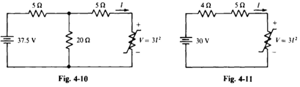
1.26 Calculate the power absorbed by each component in the circuit of Fig. 1-10.
I 6 V
0.41
Fig. 1-10
Since for the 10-A current source the current flows out of the positive terminal, the power it absorbs is P , = - 16(10) = - 160 W. The negative sign iiidicates that this source is not absorbing power but rather
is delivering power to other components in the circuit. For the 6-V source, the 10-A current flows into the negative terminal, and so P 3 = 22(6) = 132 W. Finally, the dependent source provides a current of 0.4(10) = 4 A. This current flows into the positive terminal
since this source also has 22 V, positive at the top, across it. Consequently, P4 = 22(4) = 88 W. Observe that P , = -6(10) = -60 W. For the 22-V source,
PI
+
P2+
P3+
P4 = - 160 - 60+
132+
88 = 0 WThe sum of 0 W indicates that in this circuit the power absorbed by components is equal to the power delivered. This result is true for every circuit.
1.27 How long can a 12-V car battery supply 250 A to a starter motor if the battery has 4 x 10⁶ J of chemical energy that can be converted to electric energy?
The best approach is to use t = W/P. Here,
P = V l = 12 x 250 = 3000 W
And so
w
4 x 10⁶P 3000
t = - - = - = 1333.33 s = 22.2 min
1.28 Find the current drawn from a 115-V line by a dc electric motor that delivers 1 hp. Assume
100 percent efficiency of operation.
From rearranging P = M and from the fact that 1 W/V = 1 A, P
I/ 115V IJqf
x-- - 6.48 W/V = 6.48 A
I = - = 1.w 745.7w
1.29 Find the efficiency of operation of an electric tnotor that delikxrs I hp izrhile absorbing an input of 900 W.
1.30 What is the operating efficiency of a fully loaded 2-hp dc electric motor that draws 19 A at
100 V ? (The power rating of a motor specifies the output power and not the input power.)
Since the input power is
P,,, = C'I = 100 x 19 = 1900 w
the efficiency is
1.31 Find the input pobver to a fully loaded 5-lip motor that operates at 80 percent etticienc!,.
For almost 2111 calculations. the cflicicncj, is better cxprcsscd iis ;I dccimal fraction t h i i t is the percentage
11 = P,,,,! PI,,,
diyided by 100. hrhich is 0.8 here. Then from
P(,,,( 5Jy.f 745.7
w
p = - - - X = 4.66 kW
' '1 0.8 I h Q -
1.32 Find the current drawn by a dc electric motor that delivers 2 hp while operating at 85 percent
efficiency from a 110-V line.
From P = C'I = '1,
1.33 Maximum received solar power is about I kW in'. If solar panels, which conkert solar energy to
electric energy, are 13 percent efficient, h o w many square inoters of solar cell panels are needed to supply the power to a 1600-W toaster?
The power from each square meter of solar panels is
P,,,,, = '/PI,, = 0.13 x 1000 = 130
w
So, the total solar panel area needed isI ni' I 3 0 N Area = 1600AVx = 12.3 Ill'
1.34 What horsepower must an electric motor develop to piimp water up 40 ft at the rate of 2000
gallons per hour (gal"h) if the pumping system operates at 80 percent efficiency'?
One way to solve for the power is to use the work done by the pump i n 1 h, ~vhich is the Lveight of the water lifted in 1 h times the height through which it is lifted. This work divided bj. the time taken is the power output of the pumping system. And this power divided by the cfiicicncy is the input power t o the pumping system, which is the required output poucr of the electric motor. Some nccdcd data arc that I p l of water uv5gtis 8.33 Ib, and that 1 hp = 550 ( f t . Ib) s. Thus.
CHAP. I ] BASIC CONCEPTS 13
1.35
1.36
1.37
1.38
Two systems are in cascade. One operates with an efficiency of 75 percent and the other with an efficiency of 85 percent. If the input power is 5 kW, what is the output power'?
Pou, = t/l~j2Pin = 0.75(0.85)(5000) W = 3.19 kW
Find the conversion relation between kilowatthours and joules.
The approach here is to convert from kilowatthours to watt-seconds, and then use the fact that
1 J = 1 WS:
1 kWh = 1000 W x 3600 s = 3.6 x 10' WS = 3.6 MJ
For an electric rate of 7#i/kilowatthour, what does it cost to leave a 60-W light bulb on for 8 h ?
The cost equals the total energy used times the cost per energy unit:
An electric motor delivers 5 hp while operating with an efficiency of 85 percent. Find the cost for
operating it continuously for one day (d) if the electric rate is 6$ kilowatthour.
product of this energy and the electric rate is the total cost:
The total energy used is the output power times the time of operation, all divided by the efficiency. The
6c 0 . 7 4 5 7 w 2 4 M
0.85 1 k J M x 1).d x I& = 6 3 2 = $6.32
1
Cost = 5 W X l-cyx x
Supplementary Problems
1.39 Find the charge in coulombs of ( U ) 6.28 x 10²' electrons and ( h ) 8.76 x 10" protons.
A ~ I s . (0) - 1006 C, ( h ) 140 C
1.40 How many electrons have a total charge of - 4 nC'? Ans. 2.5 x 10" electrons
1.41 Find the current flow through a switch from a steady movemcnt of ( U ) 9 0 C in 6s. ( h ) 900C in 20 min, and (c) 4 x electrons in 5 h.
A m . ( a ) 15 A, ( h ) 0.75 A, ( ( 8 ) 3.56 A
1.42 A capacitor is an electric circuit component that stores electric charge. If a capacitor charges at a steady rate to 10 mC in 0.02 ms, and if it discharges in 1 p s at a steady rate, what are the magnitudes of the charging and discharging currents?
Ans. 500 A, 10 000 A
1.43 In a gas, if doubly ionized negative ions move to the right at a steady rate of 3.62 x 10" ions per minute and if singly ionized positive ions move to the left at a steady rate of 5.83 x 10" ions per minute, find the current to the right.
Ans. -3.49 A
1.44 Find the shortest time that 120 C can flow through a 20-A circuit breaker without tripping it.
Ans. 6 s
14 BASIC CONCEPTS [<'HAP. I
1.45 If a steady current flows to a capacitor, find the time required for the capacitor to ( ( I ) charge to 2.5 mC if the
current is 35 mA, ( c ) store 9.36 x 10'- electrons if thc current is 85.6 nA. (b)
charge to 36 pC if the current is 18 pA, and
Ans. (a) 71.4 ms, (b) 2 p, (c) 20.3 d
1.46 How long can a 4.5-Ah, 1.5-V flashlight battery deliver 100 mA?
Ans. 45 h
1.47 Find the potential energy in joules lost by a 1.2-Ib book in falling off a desk that is 3 I in high.
Ans. 4.2 J
1.48 How much chemical energy must a 1.25-V flashlight battery expend in producing a current flow of 130 mA for 5 min?
Ans. 48.8 J
1.49 Find the work done by a 9-V battery in moving 5 x 102" electrons from its positive terminal to its negative terminal.
Ans. 721 J
1.50 Find the total energy available from a rechargeable 1.25-V flashlight battery with a 1.2-Ah rating.
Ans. 5.4 kJ
1.51 If all the energy in a 9-V transistor radio battery rated at 0.392 Ah is used to lift a 150-lb man. how high in feet
will he be lifted? Ans. 62.5 ft
1.52 If a charge of - 4 C in moving from point a to point h gives up 20 J of energy, what is CL,?
Ans. -5 V
1.53 Moving 6.93 x 10¹⁹ electrons from point h to point ( I requires 98 J of work. Find LLb.
Ans. -8.83 V
1.54 How much power does an electric clock require if it draws 27.3 mA from a 110-V line?
Ans. 3 W
1.55 Find the current drawn by a 1OOO-W steam iron from a 120-V line.
Ans. 8.33 A
1.56 For the circuit of Fig. 1-1 1, find the power absorbed by the current source for ( L J ) 1.' = 4 V. I = 2 mA;
(b) V = - 50 V, I = - 150 pA; (c) V = 10 mV, I = - 15 m A;
Ans. (a) -8 mW, (b) -7.5 mW, (c) 150 ,uW, ( d ) 9.6 mW
( d ) V = - 1 20 mV, I = 80 m A.
Fig. 1-1 1
CHAP.
13
BASIC CONCEPTS 151.57 For the circuit of Fig. 1-12, determine P , , P , , P , , which are powers absorbed, for 20 mA, and ( c ) I = - 3 A. Ans. (a) I = 2 A, (b) I = ( a ) P , = 16 W, P , = -24 W, P , = -20 W; (b) P , = 0.16 W, P , = -2.4 mW, P , = -0.2 W; (c) P , = -24 W, P , = -54 W, P 3 = 30 W I 8 V I
0'
61 1ov
Fig. 1-121.58 Calculate the power absorbed by each component in the circuit of Fig. 1-13.
Ans. P , = 16 W, P , = -48 W, P , = -48 W, P , = 80 W
Fig. 1-13
1.59 Find the average input power to a radio that consumes 4500 J in 3 min.
Ans. 25 W
1.60 Find the voltage drop across a toaster that gives off 7500 J of heat when a 13.64-A current flows through it for 5 s.
Ans. 110 V
1.61 How many joules does a 40-W light bulb consume in 1 d?
Ans. 3.46 MJ
1.62 How long can a 12-V car battery supply 200 A to a starter motor if the battery has 28 MJ of chemical energy that can be converted to electric energy?
Ans. 3.24 h
1.63 How long does it take a 420-W color TV set to consume (a) 2 kWh and (b) 15 kJ? Ans. ( U ) 4.76 h, ( h ) 35.7 s
16 BASIC CONCEPTS [CHAP. I
1.64 Find the current drawn by a 110-V dc electric niotor that d e l i ~ ~ s 2 hp. Assume 100 percent efficicncq of operation .
Ans. 13.6 A
1.65 Find the efficiency of operation of an electric motor that delivers 5 hp while absorbing an input of 4190 W.
Ans. 89 percent
1.66 What is the operating efficiency of a dc electric motor that delivers 1 hp while drawing 7.45 A from a 115-V line?
Ans. 87 percent
1.67 Find the current drawn by a 100-V dc electric motor that operates at 85 percent efficiency while delivering
0.5 hp.
Ans. 4.39 A
1.68 What is the horsepower produced by an automobile starter motor that draws 250 A from a 12-V battery while operating at an efficiency of 90 percent'?
Ans. 3.62 hp
1.69 What horsepower must an electric motor de\vAop to operate a pump that pumps water at a rate of 23 000 liters per hour (Lih) up a vertical distance of 50 m if the efficiency of the pump is 90 percent'? The gravitational
, force on 1 L of water is 9.78 N. Ans. 4.86 hp
1.70 An ac electric motor drives a dc electric voltage generator. If the motor operates at an efficiency of 90 percent and the generator at an efficiency of 80 percent, and if the input power to the motor is 5 kW, find the output
power from the generator.
Ans. 3.6 kW
1.71 Find the cost for one year (365 d ) to operate a 20-W transistor F M - A M radio 5 h a day if electrical energqr costs 8$/'kilowatthour.
Ans. $2.92
1.72 For a cost of $5, how long can a fully loaded 5-hp electric motor be run if the motor operates at an efficienc) of 85 percent and if the electric rate is 6c'kilowatthour'?
Ans. 19 h
1.73 If electric energy costs 6$'kilowatthour, calculate the utility bill for one month for operating eight 100-W light bulbs for 50 h each, ten 60-W light bulbs for 70 h each, one 2-kW air conditioncr for 80 h. one 3-kW range for 45 h, one 420-W color TV set for 180 h. and one 300-W refrigerator for 75 h.
Ans. $28.5 1.
Chapter 2
Resistance
OHM’S LAW
In flowing through a conductor, free electrons collide with conductor atoms and lose some kinetic
energy that is converted into heat. A n applied Froltage will cause them to regain energy and speed, but
subsequent collisions will s l o ~ them down again. This speeding up and sloiving doiz n occurs continually
as free electrons move among conductor atoms.
Resistcrncc) is this property of materials that opposes or resists the nio\ ement of electrons and makes
it necessary to apply a voltage to cause current to flo~v. The SI unit of resistance is the o h hith symbol
R, the Greek uppercase letter omega. The quantity symbol is R.
In metallic and some other types of conductors, the current is proportional to the applied voltage:
Doubling the voltage doubles the current, tripling the voltage triples the current. and s o on. If the applied
voltage I/ and resulting current I have associated references, the relation betkveen I’and I is
v
(volts){(amperes) =
R( ohms)
in which R is the constant of proportionality. This relation is kno\vn a s Olirii’s hi.. For time-varying
voltages and currents,
From Ohm’s law it is evident that, the greater the resistance, the less the current for any applied voltage. Also, the electric resistance of a conductor is 1 R if an applied koltage of 1 V causes a current
of 1 A to flow.
The inverse of resistance is often useful. I t is called c’o}illilc.tciiic*c’ and its quantit), sy111bOI is G. The
SI unit of conductance is the sicwicrzs u.ith symbol S, \i.hich is replacing the popular non-SI unit r i l l i o
with symbol U (inverted omega). Since conductance is the incerse of resistance. G = I R. I n terms of
i = 1 3 R . And for nonassociated references, I = - I ’ R or i = - r R.
conductance. Ohm’s law is hat the greater which shows
voltage.
{(amperes) = G(sie1iiens) x V(volts)
he conductance of ;i conductor, the greater the current for any applied
RESISTIVITY
The resistance of a conductor of uniform cross section is directly proportional to the length of the
conductor and inversely proportional to the cross-sectional area. Resistance is also a function of the
temperature of the conductor, a s is explained in the next section. At a fixed temperature the resistance of a conductor is
where 1 is the conductor length in meters and A is the cross-sectional area in square meters. The constant
of proportionality p, the Greek lowercase letter rho, is the quantity symbol for wsistiritj~, the factor that
depends on the type of material.
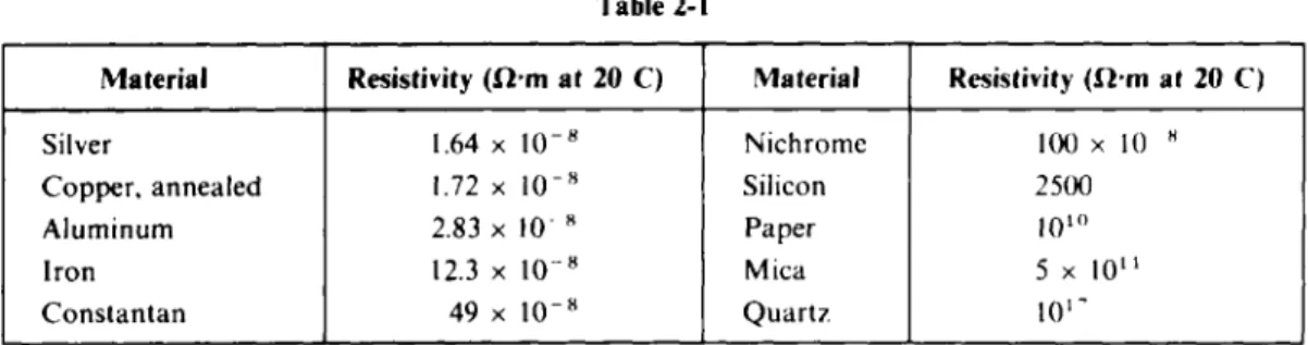
The SI unit of resistivity is the o l i m - r i i c ~ t u with unit symbol R.m. Table 2-1 sholvs the resistivities
of some materials at 20 C.
A good conductor has a resistivity close to 10 R.m. Silver, the best conductor. is too expensii-e
for most uses. Copper is a common conductor, a s is aluminum. Materials N i t h resistivities greater than
10’ C2.m are in.virkrtor..v. They can provide physical support without significant current leakage. Also,
17
R ES I STA NC E: [CHAP. 2 Resistivity (l2.m at 20' C) 1.64 x 10-fl 1.72 x 10-' 2.83 x 10-' 12.3 x to-' 49 x 10-fl
I
Material Material Nichrome Silicon Paper Mica Quartz Silver Copper, annealed Aluminurn Iron Constant an Table 2-1 Resistivity (Qrn at 20 C) 100 x 1 0 - H 2500 1 0 ' O 5 x 10" 101'insulating coatings on wires prevent current leaks between wires that touch. Materials with resistivities in the range of 10-4 to 10-7 Q.m are semiconductors, from which transistors are made.
The relationship among conductance, length, and cross-sectional area is A
G = O - 1
where the constant of proportionality 0, the Greek lowercase sigma, is the quantity symbol for
conductivity. The SI unit of conductivity is the siemens per meter with symbol S m ~
' .
TEMPERATURE EFFECTS
The resistances of most good conducting materials increase almost linearly with temperature over the range of normal operating temperatures, as shown by the solid line in Fig. 2-1. However, some materials, and common semiconductors in particular, have resistances that decrease with temperature increases.
If the straight-line portion in Fig. 2-1 is extended to the left, it crosses the temperature axis at a temperature To at which the resistance appears to be zero. This temperature To is the infcmwi zero resistance temperuture. (The actual zero resistance temperature is -273 'C.) If To is known and if the
resistance R , at another temperature T, is known, then the resistance R , at another temperature T2 is, from st raight-line geometry,
Table 2-2 has inferred zero resistance temperatures for some common conducting materials.
A different but equivalent way of finding the resistance R , is from R2 = RlC1
+
%(T2 - T1)IR I
4'
TI Fig. 2-1 Tvisit www.mrlupen.com
CHAP. 23 Table 2-2 R ESlSTA NCE Table 2-3 19 Material Tungsten Copper Aluminum Silver Constan tan Inferred zero resistance temperature ( C) - 202 - 234.5 - 236 - 243 - 125 000
Material Temperature coefficient ("C - I at 20°C) Tungsten Copper Aluminum Silver Constan tan Carbon 0.0045 0.003 93 0.003 91 0.0038 O.OO0 008 - 0.0005
where u l , with the Greek lowercase alpha, is the temperature coeflcient of resistance at the temperature Tl. Often T, is 20-C. Table 2-3 has temperature coefficients of resistance at 20°C for some common conducting materials. Note that the unit of CI is per degree Celsius with symbol " C -
'.
RESISTORS
In a practical sense a resistor is a circuit component that is used because of its resistance. Mathematically, a resistor is a circuit component for which there is an algebraic relation between its instantaneous voltage and instantaneous current such as the voltage-current relation for a resistor that obeys Ohm's law--a linear resistor. Any other type of voltage-current relation ( c = 4i2
+
6, for example) is for a nonlineur resistor. The term "resistor" usually designates a linear resistor. Nonlinear resistors are specified as such. Figure 2-2u shows the circuit symbol for a linear resistor, and Fig. 2-2b that for a nonlinear resistor.t' = iR,
RESISTOR POWER ABSORPTION
Substitution from I/ = I R into
of resistance: P
= VI gives the power absorbed by a linear resistor in terms
Every resistor has a power rating, also called wattage rating, that is the maximum power that the resistor can absorb without overheating to a destructive temperature.
NOMINAL VALUES AND TOLERANCES
Manufacturers print resistance values on resistor casings either in numerical form or in a color code. These values, though, are only nominal ualues: They are only approximately equal to the actual resistances. The possible percentage variation of resistance about the nominal value is called the tolerance. The popular carbon-composition resistors have tolerances of 20, 10, and 5 percent, which means that the actual resistances can vary from the nominal values by as much as +_ 20, +_ 10, and +_ 5 percent of the nominal values.
K ES I ST A NC E
Color Number Color Black 0 Blue Brown 1 Violet Red U Gray Orange 3 White Yellow 4 Gold Green 5 Silver 7 [CHAP. 2 Number 6 7 8 9 0.1 0.0 1 COLOR CODE
The most popular resistance color code has nominal resistance values and tolerances indicated by the colors of either three or four bands around the resistor casing, as shown in Fig. 2-3.
First Second Number of zeros
digit digit or multiplier Tolerance
Fig. 2-3
Each color has a corresponding numerical value as specified in Table 2-4. The colors of the first and second bands correspond, respectively, to the first two digits of the nominal resistance value. Because the first digit is never zero, the first band is never black. The color of the third band, except for silver and gold, corresponds to the number of zeros that follow the first two digits. A third band of silver corresponds to a multiplier of 10
’,
and a third band of gold to a multiplier of 10’.
The fourth band indicates the tolerance and is either gold- or silver-colored, or is missing. Gold corresponds to a tolerance of 5 percent, silver to 10 percent, and a missing band to 20 percent.OPEN AND SHORT CIRCUITS
An open circuit has an infinite resistance, which means that it has zero current flow through it for any finite voltage across it. On a circuit diagram it is indicated by two terminals not connected to anything
A short circuit is the opposite of an open circuit. It has zero voltage across it for any finite current flow through it. On a circuit diagram a short circuit is designated by an ideal conducting wire a wire with zero resistance. A short circuit is often called a short.
Not all open and short circuits are desirable. Frequently, one or the other is a circuit defect that occurs as a result of a component failure from an accident or the misuse of a circuit.
no path is shown for current to flow through. An open circuit is sometimes called an o p n .
INTERNAL RESISTANCE
Every practical voltage or current source has an intc~rnal resistunce that adversely affects the operation of the source. For any load except an open circuit, a voltage source has a loss of voltage across its internal resistance. And except for a short-circuit load, a current source has a loss of current through its internal resistance.
CHAP. 21 R ES I STA N C E 21
In a practical voltage source the internal resistance has almost the same effect as a resistor in series with an ideal voltage source, as shown in Fig. 2-4u. (Components in series carry the same current.) In a practical current source the internal resistance has almost the same effect as a resistor in parallel with
an ideal current source, as shown in Fig. 2-4h. (Components in parallel have the same voltage across
them.)
Practical voltage source
- 3 c - - - Internal I resistance I I
I
Practical current source
r - - - - 7 Terminals resistance current source I I
Solved
Problems
2.1 If an oven has a 240-V heating element with a resistance of 24Q, what is the minimum rating of a fuse that can be used in the lines to the heating element?
T h e fuse must be able t o carry the current of the heating element:
2.2 What is the resistance of a soldering iron that draws 0.8333 A at 120 V'? C
' 120
I 0.8333
R = = = 144R
2.3 A toaster with 8.27
sl
of resistance draws 13.9 A. Find the applied Lroltage. V = I R = 1 3 . 9 ~ 8 . 2 7 = 1 1 5 V2.4 What is the conductance of a 560-kQ resistor?
I 1
G = - = S = 1.79 p S
R 560 x 1 0 3
2.5 What is the conductance of an ammeter that indicates 20 A when 0.01 V is across i t ?