HAL Id: tel-02069224
https://pastel.archives-ouvertes.fr/tel-02069224
Submitted on 15 Mar 2019
HAL is a multi-disciplinary open access
archive for the deposit and dissemination of sci-entific research documents, whether they are pub-lished or not. The documents may come from teaching and research institutions in France or
L’archive ouverte pluridisciplinaire HAL, est destinée au dépôt et à la diffusion de documents scientifiques de niveau recherche, publiés ou non, émanant des établissements d’enseignement et de recherche français ou étrangers, des laboratoires
produced by means of Additive Layer Manufacturing
processes
Giulio Costa
To cite this version:
Giulio Costa. Design and Optimisation Methods for Structures produced by means of Additive Layer Manufacturing processes. Chemical and Process Engineering. Ecole nationale supérieure d’arts et métiers - ENSAM, 2018. English. �NNT : 2018ENAM0035�. �tel-02069224�
Arts et Métiers ParisTech - Campus de Bordeaux Institut de Mécanique et d’Ingénierie – I2M, UMR CNRS 5295
2018-ENAM-0035
École doctorale n° 432 : Science des Métiers de l’ingénieur
présentée et soutenue publiquement par
Giulio COSTA
le 22 octobre 2018
Design and Optimisation Methods for Structures produced
by means of Additive Layer Manufacturing processes
Doctorat ParisTech
T H È S E
pour obtenir le grade de docteur délivré par
l’École Nationale Supérieure d'Arts et Métiers
Spécialité “ Conception ”
Directeur de thèse : Jérôme PAILHÈS Co-encadrement de la thèse : Marco MONTEMURRO
T
H
È
S
E
JuryM. Philippe VERON, Professeur des Universités, LSIS, UMR CNRS 7296, ENSAM Aix-en-Provence Président
M. Grégoire ALLAIRE, Professeur des Universités, CMAP, UMR CNRS 7641, Ecole Polytechnique Rapporteur
M. Alberto PIRRERA, Senior Lecturer, ACCIS, University of Bristol Rapporteur
M. Paolo VANNUCCI, Professeur des Universités, LMV, UMR 8100, Université de Versailles Examinateur
M. Frédéric VIGNAT, Maître de Conférences HDR, G-SCOP, UMR CNRS 5272, Grenoble INP Examinateur
M. Marco MONTEMURRO, Maître de Conférences, I2M, UMR CNRS 5295, ENSAM Bordeaux Examinateur
M. Jérôme PAILHÈS, Professeur des Universités, I2M, UMR CNRS 5295, ENSAM Bordeaux Examinateur
I would like to thank my supervisors J´erˆome Pailh`es and Marco Montemurro for having given me the opportunity to improve as a researcher and as an engineer through this PhD thesis project. Beyond their scientific values, J´erˆome’s broad vision and Marco’s incredible persistence in facing research problems constitute both exemplary attitudes for a young researcher. My sincerest thanks are addressed to the I2M Laboratory, to the industrial partners and to the Nouvelle-Aquitaine region for having supported the FUTURPROD project. I am particularly grateful to St´even Robidou, Florine Weil and Thierry Gomez-Lavocat for their time and for their interest in my work.
Never before I needed to say “thank you” to my parents as at this moment. During bad moments in these last three years I joked with them by saying that it was their fault for my loneliness in Bordeaux, because they made me feel beloved. Always. For 25 years before leaving my place in Pisa and later on. Maybe I exaggerated, but it is not so far from truth. Thank you Sandro and Lucia for all.
Thank you also to you, Laura. I swear that I have never doubted about the strength of our love. However, these last three years were not just a prove of love; they have been a prove of respect and of sincere care for each other. I really want to say thank you for having been always on my side, for having laughed with me and for having cried with me. I will keep doing my best to deserve you.
Gabriele, my little big brother, you are someone very special to me, someone to es-timate for his young genuineness. Thank you for your fresh optimistic and sometimes non-realistic way to look at the world.
I would like to thank my families. The first one is constituted of my relatives: my grandmother, my uncles and aunts, my cousins. You have been the kernel of my happiness in childhood, in adolescence and in adult life. A particular thought is dedicated to my uncle Pierluigi and my aunt Simona, which have followed this experience with passion, love and admiration. I am also extremely grateful to Francesca and Giuseppe for having always encouraged me and Laura in both our studies and in our life together. You all constitute my happiest memories. The second family is made of friends, especially those “ritals” which have shared this experience with me: Lorenzo, Michele, Pietro thank you for having been my strongest support in Bordeaux. A special mention is for you, Yohann. I have found a true friend with an unbelievable intellectual honesty, easy to misunderstand with ingenuity. Thank you for your infinite kindness.
Finally, I am sincerely grateful to those people who have somehow supported me along the way (no matter the eventual distance between us): thank you Anita, Antone, Antonio, Enrico, Giacinto Alberto, Giovanni, Grace, Luca, Maria Antonietta, M´elissande, Paolo, Torquato.
Je voudrais remercier mes encadrants J´erˆome Pailh`es et Marco Montemurro pour la possibilit´e qu’ils m’ont donn´e de m’am´eliorer et de m’´epanouir en tant que chercheur et ing´enieur `a travers cette th`ese de doctorat. Au-del`a de leur valeur scientifique, la vision d’ensemble de J´erˆome et la pers´ev´erance de Marco quand il s’agit d’aborder un probl`eme de recherche sont des qualit´es exemplaires pour un jeune chercheur. Mes remerciements les plus sinc`eres sont adress´es au Laboratoire I2M, aux partenaires industriels et `a la r´egion Nouvelle-Aquitaine pour avoir soutenu le projet FUTURPROD. Je suis particuli`erement reconnaissant envers St´even Robidou, Florine Weil et Thierry Gomez-Lavocat pour leur temps et pour l’int´erˆet montr´e envers mes travaux.
Maintenant plus que jamais, je sens le besoin de dire “merci” `a mes parents. Pendant les mauvaises p´eriodes je rigolais avec eux en disant que si je me sentais seul, et bien c’´etait leur faut parce qu’ils m’ont vraiment aim´e. Toujours, pendant 25 ann´ees avant de laisser Pisa. Peut-ˆetre que j’exag`ere, mais cela n’est pas trop loin de la v´erit´e. Merci Sandro et Lucia pour tout.
Merci `a toi aussi, Laura. Je jure que je n’ai jamais eu des doutes concernant notre amour. Cependant, ces derni`eres ann´ees n’ont pas ´et´e seulement une d´emonstration d’amour; ils ont ´et´e une preuve de respect et de soin sinc`ere de l’un pour l’autre. Je veux vraiment te remercier pour avoir toujours ´et´e de mon cˆot´e, pour avoir ri avec moi et pour avoir pleur´e avec moi. Je vais continuer de faire de mon mieux pour te m´eriter.
Gabriele, mon petit grand fr`ere, tu es quelqu’un de tr`es sp´ecial pour moi, quelqu’un `a estimer pour son jeune authenticit´e. Merci pour ta vision du monde si fraˆıche, optimiste et parfois mˆeme un peu non r´ealiste.
Je voudrais remercier mes familles. La premi`ere est form´ee par mes proches: ma grand-m`ere, mes oncles, mes tantes et mes cousins. Vous avez ´et´e le noyau de mon bonheur pendant l’enfance, l’adolescence et la vie d’adulte. Une pens´ee particuli`ere est adress´ee `a mon oncle Pierluigi et ma tante Simona, qui ont suivi mon exp´erience avec enthousiasme, affection et admiration. Je suis aussi tr`es reconnaissant `a Francesca et Giuseppe pour avoir toujours encourag´e Laura et moi pour nos ´etudes et pour notre vie ensemble. Vous tous constituez mes souvenirs les plus chers. La seconde famille est faite par des amis, notamment ceux “ritals” qui ont partag´e cette exp´erience avec moi: merci Lorenzo, Michele et Pietro pour avoir ´et´e mon support le plus important `a Bordeaux. Il faut faire une mention sp´eciale pour toi, Yohann. J’ai trouv´e un vrai ami, avec une honnˆetet´e intellectuelle incroyable, trop facilement confondue avec ing´enuit´e. Merci pour ta gentillesse infinie.
Enfin, je suis vivement reconnaissant `a toutes les personnes qui m’ont support´e en chemin de quelque mani`ere (peu importe l’´eventuelle distance entre nous): merci Anita, Antone, Antonio, Enrico, Giacinto Alberto, Giovanni, Grace, Luca, Maria Antonietta, M´elissande, Paolo, Torquato.
Vorrei ringraziare i miei inquadranti J´erˆome Pailh`es e Marco Montemurro per la pos-sibilit`a che mi hanno dato di migliorare come ricercatore e come ingegnere attraverso questa tesi di dottorato. Al di l`a del loro valore scientifico, la visione d’insieme di J´erˆome e la perseveranza di Marco nell’affrontare un problema di ricerca sono delle qualit`a es-emplari per un giovane ricercatore. Inoltre, i miei ringraziamenti pi`u sinceri vanno al Laboratorio I2M, ai partner industriali e alla regione Nouvelle-Aquitaine per aver sup-portato il progetto FUTURPROD. Sono particolarmente riconoscente a St´even Robidou, Florine Weil e Thierry Gomez-Lavocat per il loro tempo e l’interesse mostrato verso il mio lavoro.
Adesso come non mai, sento il bisogno di dire “grazie” ai miei genitori. Durante i brutti periodi scherzavo con loro dicendo che erano loro la causa del mio sentirmi solo. Questo perch´e mi hanno fatto sempre sentire tanto amato. Sempre, durante 25 anni prima di lasciare Pisa e dopo anche di pi`u. Forse esagero, ma non sono troppo lontano dalla verit`a. Grazie babbo Sandro e mamma Lucia per tutto.
Grazie anche a te, Laura. Giuro che non ho mai avuto dubbi sulla forza del nostro amore. Tuttavia, questi ultimi anni non sono stati solamente una dimostrazione d’amore ma una prova di rispetto e di cura dell’uno per l’altro. Voglio veramente ringraziarti per essere sempre stata al mio fianco, per aver riso con me e per aver pianto con me. Continuer`o a fare del mio meglio per meritarti.
Gabriele, mio grande fratellino, tu sei qualcuno davvero speciale per me, qualcuno da stimare per la sua giovane genuinit`a. Grazie per la tua visione del mondo cos`ı fresca, ottimista e talvolta anche un po’ non realista.
Vorrei poi ringraziare le mie due famiglie. La prima `e formata dai miei parenti: mia nonna, i miei zii e le mie zie, i miei cugini. Siete stati il nucleo della mia felicit`a durante l’infanzia, l’adolescenza e nella vita adulta. Un pensiero particolare `e rivolto ai miei zii Pierluigi e Simona, che hanno seguito questa mia esperienza con trasporto, affetto e ammirazione. Sono anche estremamente riconoscente a Francesca e Giuseppe per aver sempre incoraggiato me e Laura tanto nei nostri rispettivi studi quanto nella nostra vita insieme. Voi tutti costituite i miei ricordi pi`u cari. La seconda famiglia `e fatta da amici, in particolare da quei “ritals” che hanno condiviso questo percorso con me: grazie Lorenzo, Michele e Pietro per essere stati il mio maggiore supporto a Bordeaux. Una menzione speciale `e per te, Yohann. Ho trovato in te un vero amico, con un’onest`a intellettuale incredibile, troppo facilmente confondibile con l’ingenuit`a. Grazie per la tua gentilezza infinita.
Infine, sono davvero grato a tutti coloro che in qualche modo mi hanno supportato durante questo percorso, indipendentemente dalla distanza che ci divideva: grazie Anita, Antone, Antonio, Enrico, Giacinto Alberto, Giovanni, Grace, Luca, Maria Antonietta, M´elissande, Paolo, Torquato.
List of Figures viii
List of Tables xiv
Introduction 1
The Thesis Context and the FUTURPROD Project . . . 1
Optimisation, Design and CAD in the ALM Framework . . . 3
Thesis Objectives . . . 6
Thesis Outline . . . 7
Introduction 9 Contexte de la th`ese et le projet FUTURPROD . . . 9
Int´egration de l’optimisation, de la conception et de la CAO . . . 11
Objectifs de la th`ese . . . 14
Structure de la th`ese . . . 14
1 Literature Review 17 1.1 Introduction to the Literature Review . . . 17
1.2 The Additive Layer Manufacturing Technology . . . 17
1.2.1 A classification of ALM processes . . . 18
1.2.2 The Selective Laser Melting Technology . . . 20
1.3 Topology Optimisation Methods . . . 23
1.3.1 Density-Based Methods . . . 23
1.3.2 The Level-Set Method . . . 29
1.4 Implementation of Manufacturing Constraints in Topology Optimisation . 36 1.5 Conclusions on the Literature Review . . . 38
1 Revue de la litt´erature 41 1.1 Introduction de la revue de la litt´erature . . . 41
1.2 La technologie de fabrication additive par couche (Additive Layer Manufac-turing) . . . 41
1.2.1 Classification des processus ALM . . . 42
1.2.2 La technologie de fusion s´elective par laser (SLM) . . . 43
1.3 M´ethodes d’Optimisation Topologique . . . 45
1.3.1 M´ethodes bas´ees sur la densit´e . . . 45
1.3.2 La M´ethode Level-Set . . . 47
1.4 Impl´ementation des contraintes de l’ALM dans l’OT . . . 51
1.5 Conclusions de la revue de la litt´erature . . . 53
2 Fundamentals of Geometrical Modelling 55 2.1 Introduction to the Fundamentals of Geometrical Modelling . . . 55
2.2 The NURBS curves theory . . . 55
2.3 The NURBS surfaces theory . . . 59
2.4 The NURBS hyper-surfaces theory . . . 61
2.5 Conclusions on the NURBS entities theory . . . 63
2 Principes fondamentaux de la mod´elisation g´eom´etrique 65 2.1 Introduction aux Principes fondamentaux de la mod´elisation g´eom´etrique . 65 2.2 La th´eorie des courbes NURBS . . . 65
2.3 La th´eorie des surfaces NURBS . . . 66
2.4 La th´eorie des hyper-surfaces NURBS . . . 68
2.5 Conclusions sur la th´eorie des entit´es NURBS . . . 69
3 Optimisation Methods and Algorithms 71 3.1 Introduction to Optimisation Methods . . . 71
3.2 Deterministic Methods for CNLPP . . . 74
3.2.1 Generalities on Deterministic Methods . . . 74
3.2.2 Optimality Conditions for CNLPP . . . 76
3.2.3 Deterministic Algorithms for CNLPP . . . 77
3.3 Meta-heuristic Methods for CNLPP . . . 81
3.3.1 Generalities on Meta-heuristics . . . 81
3.3.2 The Genetic Algorithm BIANCA . . . 82
3.3.3 The MATLAB version of BIANCA . . . 91
3.4 Conclusions on Optimisation Methods and Algorithms . . . 93
3 M´ethodes et algorithmes d’optimisation 95 3.1 Introduction aux m´ethodes d’optimisation . . . 95
3.2 M´ethodes d´eterministes pour les probl`emes de type CNLPP . . . 97
3.2.1 G´en´eralit´es sur les m´ethodes d´eterministes . . . 97
3.2.2 Conditions d’optimalit´e pour les CNLPP . . . 98
3.2.3 Algorithmes d´eterministiques pour les CNLPP . . . 98
3.3.1 G´en´eralit´es sur les m´eta-heuristiques . . . 100
3.3.2 L’algorithme g´en´etique BIANCA . . . 100
3.3.3 La version MATLAB de BIANCA . . . 103
3.4 Conclusions sur les m´ethodes et algorithmes d’optimisation . . . 104
4 A NURBS-based Topology Optimisation Algorithm 107 4.1 Introduction . . . 107
4.2 Mathematical Formulation of the NURBS-based Topology Optimisation Method . . . 109
4.3 The algorithm SANTO (SIMP And NURBS for Topology Optimisation) . 115 4.4 Results Discussion . . . 122
4.4.1 The 2D benchmark . . . 122
4.4.2 Results for 2D problems: sensitivity to the NURBS surface degrees, number of control points and weights . . . 123
4.4.3 Results for 2D problems: comparison between classical and NURBS-based SIMP approaches . . . 128
4.4.4 Results for 2D problems: influence of Non-Design Regions . . . 129
4.4.5 Results for 2D problems: influence of a symmetry constraint . . . . 130
4.4.6 The 3D benchmarks . . . 131
4.4.7 Results for 3D problems: sensitivity to the NURBS hyper-surface degrees, number of control points and weights . . . 133
4.4.8 Results for 3D problems: comparison between classical and NURBS-based SIMP approaches . . . 140
4.5 Conclusions and Perspectives on the NURBS-based TO Algorithm . . . 144
4 Un algorithme d’Optimisation Topologique bas´e sur les entit´es NURBS149 4.1 Introduction . . . 149
4.2 Formulation Math´ematique de la M´ethode d’Optimisation Topologique bas´ee sur les NURBS . . . 150
4.3 L’algorithme SANTO (SIMP And NURBS for Topology Optimisation) . . . 152
4.4 Discussion des R´esultats . . . 154
4.4.1 Le benchmark 2D . . . 155
4.4.2 R´esultats pour les probl`emes 2D : sensibilit´e aux param`etres de la surface NURBS . . . 155
4.4.3 R´esultats pour les probl`emes 2D : comparaison entre la m´ethode SIMP classique et l’algorithme bas´e sur les NURBS . . . 156
4.4.4 R´esultats pour les probl`emes 2D : influence de Non-Design Regions . 156 4.4.5 R´esultats pour les probl`emes 2D : influence d’une contrainte de sym´etrie157 4.4.6 Les benchmarks 3D . . . 157
4.4.7 R´esultats pour les probl`emes 3D : sensibilit´e aux param`etres de l’hyper-surface NURBS . . . 157
4.4.8 R´esultats pour les probl`emes 3D : comparaison entre la m´ethode SIMP classique et l’algorithme bas´e sur les NURBS . . . 158 4.5 Conclusions et Perspectives concernant l’Algorithme d’OT bas´e sur les NURBS160 5 Geometrical Constraints Implementation in the Framework of the NURBS-based Topology Optimisation Algorithm 163 5.1 Introduction to Geometrical Constraints in Topology Optimisation . . . 163 5.2 Poulsen’s Formulation of the Minimum Length Scale Constraint . . . 167
5.2.1 Mathematical Statement of Poulsen’s Minimum Length Scale con-straint . . . 167 5.2.2 Poulsen’s Minimum Length Scale constraint: numerical results . . . 169 5.3 Minimum Length Scale control in the NURBS-based TO Algorithm . . . . 171 5.3.1 Minimum length scale resulting from B-Spline entities . . . 171 5.3.2 Some remarks about the proposed approach . . . 180 5.3.3 The effects of the NURBS weights on the minimum length scale . . 181 5.3.4 Results: Minimum length scale in 2D . . . 184 5.3.5 Results: Minimum length scale in 3D . . . 186 5.3.6 The effects of a non-uniform knot vector on the minimum length scale191 5.4 The Maximum Length Scale . . . 194 5.4.1 Mathematical Statement of the Maximum Length Scale constraint . 194 5.4.2 Results: Maximum Length Scale in 2D . . . 196 5.4.3 Results: Maximum Length Scale in 3D . . . 198 5.5 The Minimum Curvature Radius . . . 199
5.5.1 Mathematical Statement of the Minimum Curvature Radius con-straint . . . 199 5.5.2 Results on the application of the Minimum Curvature Radius
con-straint . . . 201 5.6 Conclusions and Perspectives on Geometrical Constraints in the
NURBS-based TO algorithm . . . 202 5 Impl´ementation de Contraintes G´eom´etriques dans l’Algorithme d’OT
bas´e sur les NURBS 207
5.1 Introduction aux Contraintes G´eom´etriques en OT . . . 207 5.2 La formulation de Poulsen pour la contrainte de l’´epaisseur minimale . . . . 208
5.2.1 L’´enonc´e math´ematique de la contrainte de l’´epaisseur minimale selon Poulsen . . . 208 5.2.2 La contrainte de l’´epaisseur minimale selon Poulsen : r´esultats . . . . 209 5.3 Le contrˆole de l’´epaisseur minimale dans l’algorithme d’OT bas´e sur les
NURBS . . . 210 5.3.1 L’´epaisseur minimale r´esultant des entit´es B-Spline . . . 210 5.3.2 Quelques remarques sur l’approche propos´ee . . . 211
5.3.3 Les effets des poids des NURBS sur l’´epaisseur minimale . . . 212
5.3.4 R´esultats : l’´epaisseur minimale en 2D . . . 212
5.3.5 R´esultats : l’´epaisseur minimale en 3D . . . 213
5.3.6 Les effets d’un knot vector non uniforme sur l’´epaisseur minimale . . 214
5.4 L’´epaisseur maximale dans l’algorithme d’OT bas´e sur les NURBS . . . 214
5.4.1 L’´enonc´e math´ematique de la contrainte de l’´epaisseur maximale . . 214
5.4.2 R´esultats : l’´epaisseur maximale en 2D . . . 215
5.4.3 R´esultats : l’´epaisseur maximale en 3D . . . 216
5.5 Le rayon minimal de courbure . . . 216
5.5.1 Enonc´e math´ematique de la contrainte sur le rayon minimal de courbure216 5.5.2 R´esultats : application de la contrainte sur le rayon minimal de courbure217 5.6 Conclusions et Perspectives concernant les contraintes g´eom´etriques dans l’Algorithme d’OT bas´e sur les NURBS . . . 217
6 Eigenvalue Problems in the Framework of the NURBS-Based Topology Optimisation Algorithm 219 6.1 Introduction . . . 219
6.2 Eigenvalue Buckling Problems . . . 223
6.2.1 First buckling load maximisation in the classic SIMP framework . . 223
6.2.2 Mathematical formulation of buckling problems in the NURBS-based TO algorithm . . . 226
6.2.3 Discussion on numerical aspects . . . 226
6.2.4 Results . . . 229
6.3 Eigen-frequencies Problems . . . 235
6.3.1 First Eigen-frequency maximisation in the classic SIMP framework 235 6.3.2 Mathematical formulation of eigen-frequencies problems in the NURBS-based TO algorithm . . . 237
6.3.3 Discussion on numerical aspects . . . 237
6.3.4 Results . . . 238
6.4 Conclusions and Perspectives . . . 243
6 Probl`emes aux valeurs propres dans le cadre de l’algorithme d’OT bas´e sur les NURBS 247 6.1 Introduction . . . 247
6.2 Probl`emes de flambage aux valeurs propres . . . 249
6.2.1 Maximisation de la premi`ere charge critique de flambage dans la m´ethode SIMP classique . . . 249
6.2.2 Enonc´e math´ematique des probl`emes de flambage dans l’algorithme d’OT bas´e sur les NURBS . . . 250
6.2.3 Discussion sur les aspects num´eriques . . . 251
6.3 Probl`emes de fr´equences propres . . . 253
6.3.1 Maximisation de la premi`ere fr´equence propre dans la m´ethode SIMP classique . . . 253
6.3.2 Enonc´e math´ematique des probl`emes de fr´equences propres dans l’algorithme d’OT bas´e sur les NURBS . . . 254
6.3.3 Discussion sur les aspects num´eriques . . . 254
6.3.4 R´esultats . . . 254
6.4 Conclusions et Perspectives . . . 256
7 General Fitting Techniques for Curves and Surfaces Reconstruction 259 7.1 Introduction to Curve and Surface Reconstruction . . . 259
7.2 A General Hybrid Optimisation Strategy for Curve Fitting in the NURBS Framework . . . 263
7.2.1 Mathematical Formulation of the Curve Fitting Problem . . . 263
7.2.2 Numerical Strategy . . . 268
7.2.3 Studied Cases and Results for curve fitting . . . 269
7.3 Surface Reconstruction in the NURBS Framework . . . 280
7.3.1 Surface Parametrisation . . . 281
7.3.2 Surface Fitting . . . 282
7.3.3 Results on Surface Fitting . . . 284
7.4 Conclusions and Perspectives on Approximation Problems . . . 285
7 Techniques de Fitting g´en´erales pour la Reconstruction CAO de Courbes et de Surfaces 291 7.1 Introduction `a la Reconstruction de Courbes et Surfaces . . . 291
7.2 Une strat´egie d’Optimisation Hybride G´en´erale pour le Fitting des Courbes dans le cadre NURBS . . . 293
7.2.1 L’´enonc´e math´ematique du probl`eme de Fitting de Courbes . . . 293
7.2.2 Strat´egie Num´erique . . . 295
7.2.3 Cas d’´etude et R´esultats pour le Fitting de Courbes . . . 295
7.3 Reconstruction de Surfaces le cadre des NURBS . . . 298
7.3.1 Param´etrage de Surfaces . . . 298
7.3.2 Fitting de Surfaces . . . 299
7.3.3 R´esultats du Fitting de Surfaces . . . 300
7.4 Conclusions sur les Probl`emes d’Approximation . . . 300
Conclusions and Perspectives 303 General Conclusions . . . 303
Conclusions et Perspectives 309 Conclusions G´en´erales . . . 309 Les Perspectives de la Th`ese . . . 311
Annexe A 315
NURBS entities : derivatives computation . . . 315
Annexe B 317
Sensitivity analysis of the minimum member size constraint (Poulsen’s formulation)317
Annexe C 319
Sensitivity analysis of the maximum member size constraint . . . 319
Annexe D 321
Sensitivity analysis of the minimum curvature radius constraint . . . 321
Annexe E 323
Details of the NURBS curve of the flame problem . . . 323
Bibliography 325
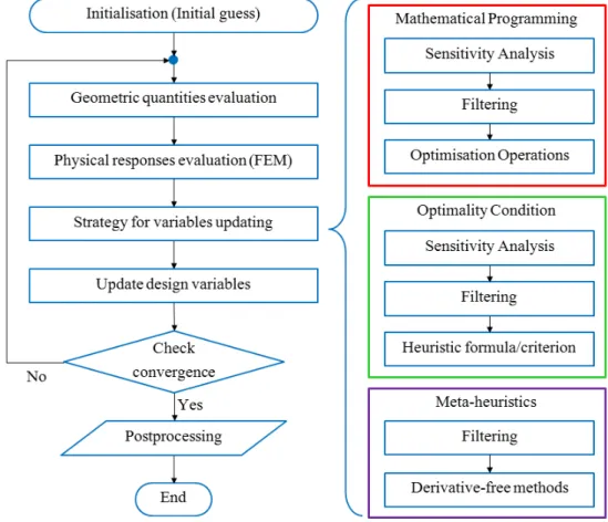
1 ALM Structures Design Loop . . . 5
1.1 Critical Angle for supported overhangs. . . 22
1.2 Representation of a general 3D structure through the SIMP fictitious dens-ity field. . . 25
1.3 Classic SIMP algorithm. . . 28
1.4 Example of Level Set Function. . . 30
1.5 Overview of the LSM. . . 31
1.6 Boundary evolution with (left) or without (right) “viscous term” [1]. . . 34
2.1 Example of Blending Functions for B-Spline/NURBS curves of degree p1 = 3 and number of control points n1 = 6. . . 57
2.2 Example of B-Spline and NURBS curves of degree p1 = 3 and number of control points n1 = 6. . . 58
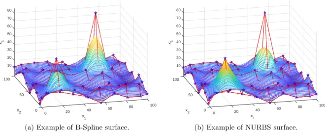
2.3 B-Spline and NURBS surfaces with same degrees, control points and knot vectors. . . 60
2.4 B-Spline and NURBS hyper-surfaces with same degrees, control points and knot vectors. . . 64
2.5 Iso-level corresponding to 10 of B-Spline and NURBS hyper-surfaces. . . . 64
3.1 Classification of optimisation algorithm. . . 73
3.2 Overview of the SQP algorithm. . . 78
3.3 Overview of the IP algorithm. . . 80
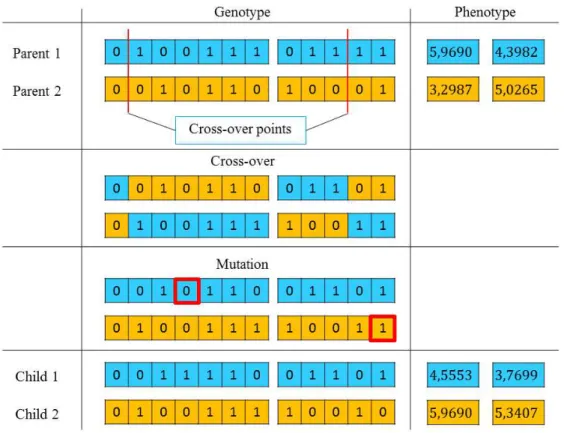
3.4 GAs: an example. . . 83
3.5 Individual Structure for problem (3.9). . . 84
3.6 Example of optimisation of modular system. . . 86
3.7 The GA BIANCA. . . 87
3.8 Reproduction phase in a standard GA. . . 89
3.9 Modified reproduction phase between different species for optimisation of modular systems. . . 90
4.1 SIMP pseudo-density representation through NURBS entities. . . 110
4.2 SANTO flowchart . . . 116
4.3 Examples of possible mirror symmetries for 3D TO problems . . . 116
4.4 Example of embedding domain, reference system and control points for a 3D component. . . 117
4.5 Postprocessing procedure for 2D structures. . . 120
4.6 Postprocessing procedure for 3D structures. . . 121
4.7 Cantilever plate problem - a1 = 320 mm, a2 = 200 mm, Thickness t = 2 mm, Young’s Modulus E = 72000 MPa, Poisson’s ratio ν = 0.33, Load P = 1000 N. . . 123
4.8 B-Spline results for p1, p2 = 2 . . . 124
4.9 NURBS results for p1, p2 = 2 . . . 124
4.10 B-Spline results for p1, p2 = 3 . . . 125
4.11 NURBS results for p1, p2 = 3 . . . 125
4.12 B-Spline results for p1, p2 = 4 . . . 125
4.13 NURBS results for p1, p2 = 4 . . . 126
4.14 Cantilever plate problem - True compliance trends. . . 126
4.15 Cantilever plate problem - Projected compliance trends. . . 127
4.16 Hyperworks-OptiStruct R solution of the cantilever plate problem: c = 398.66 N mm, V /Vref = 0.3992. . . 129
4.17 Cantilever plate problem with NDRs: design domain in white, prescribed material NDR in red, prescribed void NDR in yellow. . . 129
4.18 Cantilever plate problem with NDRs. . . 130
4.19 Cantilever plate problem with symmetry constraint. . . 131
4.20 Problem settings of the first benchmark . . . 132
4.21 Problem settings of the second benchmark . . . 133
4.22 Benchmark 1, p1 = p2 = p3 = 2, ntot = 36 × 6 × 10 . . . 135 4.23 Benchmark 1, p1 = p2 = p3 = 2, ntot = 40 × 8 × 12 . . . 135 4.24 Benchmark 1, p1 = p2 = p3 = 2, ntot = 46 × 10 × 14 . . . 135 4.25 Benchmark 1, p1 = p2 = p3 = 3, ntot = 36 × 6 × 10 . . . 136 4.26 Benchmark 1, p1 = p2 = p3 = 3, ntot = 40 × 8 × 12 . . . 136 4.27 Benchmark 1, p1 = p2 = p3 = 3, ntot = 46 × 10 × 14 . . . 136 4.28 Benchmark 1, p1 = p2 = p3 = 4, ntot = 36 × 6 × 10 . . . 137 4.29 Benchmark 1, p1 = p2 = p3 = 4, ntot = 40 × 8 × 12 . . . 137 4.30 Benchmark 1, p1 = p2 = p3 = 4, ntot = 46 × 10 × 14 . . . 137
4.31 Synthetic results: Objective function vs Iterations . . . 138
4.32 Objective function ratio vs hyper-surfaces degrees . . . 139
4.33 Solutions of the first benchmark provided by the commercial software OptiStruct R140 4.34 Comparison of the proposed methodology and the commercial software OptiStruct R . . . 142
4.35 Comparison for the second benchmark case. . . 143 5.1 Cantilever plate problem, dmin = 16 mm. . . 170
5.2 Cantilever plate problem, dmin = 20 mm. . . 170
5.3 Cantilever plate problem, dmin = 25 mm. . . 170
5.4 Simulation of 2D minimum length scale . . . 172 5.5 Simulation of 3D minimum length scale. . . 173 5.6 dmin trends in 2D, pj = 3. . . 175 5.7 dmin trends in 3D, pj = 3. . . 175 5.8 dmin vs. ∆X, pj = 3. . . 176 5.9 dmin vs. ∆X, pj = 2. . . 176 5.10 dmin vs. ∆X, pj = 4. . . 177 5.11 dmin vs. n/a, pj = 2. . . 177 5.12 dmin vs. n/a, pj = 3. . . 178 5.13 dmin vs. n/a, pj = 4. . . 178 5.14 dBmin vs. ∆X0, pj = 2. . . 179 5.15 dBmin vs. ∆X0, pj = 3. . . 179 5.16 dB min vs. ∆X0, pj = 4. . . 180
5.17 The 2D optimised topology provided by the NURBS-based SIMP method. 182 5.18 Weights and Control Points trends for a NURBS solution. . . 183 5.19 2D benchmark - Geometric parameters: a1 = 320 mm, a2 = 200 mm,
thickness t = 2 mm Material parameters: E = 72000 MPa, ν = 0.33 -Mesh: 96 × 60 SHELL181 elements - Load: P = 1000 N. . . 184 5.20 Procedure to measure the actual minimum member size. . . 185 5.21 2D solutions - minimum length scale, pj = 3. . . 186
5.22 3D benchmark - Geometric parameters: a1 = 400 mm, a2 = 100 mm,
a3 = 200 mm - Material parameters: E = 72000 MPa, ν = 0.33 - Mesh:
64 × 16 × 32 SOLID185 elements - Load: P = 2000 N. . . 187 5.23 Highlight of the minimum length scale in 3D, B-Spline solution, pj = 3,
24 × 6 × 12 control points. . . 189 5.24 Highlight of the minimum length scale in 3D, B-Spline solution, pj = 3,
30 × 12 × 18 control points. . . 189 5.25 Highlight of the minimum length scale in 3D, B-Spline solution, pj = 3,
36 × 18 × 24 control points. . . 190 5.26 Highlight of the minimum length scale in 3D, NURBS solution, pj = 3,
24 × 6 × 12 control points. . . 190 5.27 Highlight of the minimum length scale in 3D, NURBS solution, pj = 3,
30 × 12 × 18 control points. . . 191 5.28 Highlight of the minimum length scale in 3D, NURBS solution, pj = 3,
36 × 18 × 24 control points. . . 191 5.29 Knot vectors distributions. . . 192
5.30 B-Spline solutions with different knot vector distributions. . . 193 5.31 NURBS solutions with different knot vector distributions. . . 193 5.32 Traction plate problem - a1 = 400 mm, a2 = 200 mm, Thickness t = 2
mm, Young’s Modulus E = 72000 MPa, Poisson’s ratio ν = 0.33, Load P = 1000 N. . . 196 5.33 NURBS-based SIMP solutions for the traction plate problem (a) without
and (b) with maximum member size constraint. . . 197 5.34 OptiStruct R solution of the traction plate problem (a) without and (b)
with maximum member size constraint. . . 197 5.35 3D benchmark - Geometric parameters: a1 = 500 mm, a2 = 100 mm,
a3 = 200 mm - Material parameters: E = 72000 MPa, ν = 0.33 - Mesh:
60 × 16 × 24 SOLID185 elements - Load: P = 5000 N. . . 199 5.36 3D TO result - Compliance minimisation with equality constraint on the
volume. . . 199 5.37 3D TO result - Compliance minimisation with equality volume constraint
and maximum member size constraint. . . 200 5.38 Solution of the cantilever plate problem (a) without and (b) with the
min-imum local curvature radius constraint . . . 202 6.1 The fσ/fλ ratio. . . 228
6.2 The base-thickness as Non-Design Region. . . 228 6.3 Geometric parameters: a1 = 900 mm, a2 = 300 mm, d = 20 mm, thickness
t = 2 mm, symmetry plane x2 = a2/2 - Material Parameters: Steel, Young’s
modulus E = 200000 MPa, Poisson’s ratio ν = 0.3 - Loads: Unit vectors . 229 6.4 Double penalisation scheme: B-Spline results, p1, p2 = 2. . . 231
6.5 Double penalisation scheme: B-Spline results, p1, p2 = 3. . . 231
6.6 Double penalisation scheme: B-Spline results, p1, p2 = 4. . . 231
6.7 Double penalisation scheme: NURBS results, p1, p2 = 2. . . 231
6.8 Double penalisation scheme: NURBS results, p1, p2 = 3. . . 231
6.9 Double penalisation scheme: NURBS results, p1, p2 = 4. . . 232
6.10 Double penalisation technique: synthesis of results. . . 232 6.11 Base-thickness strategy: B-Spline results for p1, p2 = 2. . . 233
6.12 Base-thickness strategy: B-Spline results for p1, p2 = 3. . . 233
6.13 Base-thickness strategy: B-Spline results for p1, p2 = 4. . . 233
6.14 Base-thickness strategy: NURBS results for p1, p2 = 2. . . 233
6.15 Base-thickness strategy: NURBS results for p1, p2 = 3. . . 233
6.16 Base-thickness strategy: NURBS results for p1, p2 = 4. . . 234
6.17 Base-thickness strategy: synthesis of results. . . 234 6.18 The fω/ρe ratio. . . 238
6.19 Geometric parameters: a1 = a2 = 160 mm, d = 20 mm, thickness t = 2
mm - Material Parameters: Aluminium Alloy, Young’s modulus E = 72000 MPa, Poisson’s ratio ν = 0.33 - Non-Structural Mass: mN S = 40 Kg. . . . 239
6.20 Eigen-frequencies problem: B-Spline results, p1, p2 = 2. . . 241
6.21 Eigen-frequencies problem: B-Spline results, p1, p2 = 3. . . 241
6.22 Eigen-frequencies problem: B-Spline results, p1, p2 = 4. . . 241
6.23 Eigen-frequencies problem: NURBS results, p1, p2 = 2. . . 242
6.24 Eigen-frequencies problem: NURBS results, p1, p2 = 3. . . 242
6.25 Eigen-frequencies problem: NURBS results, p1, p2 = 4. . . 242
6.26 Eigen-frequencies problem: synthesis of results. . . 243 7.1 Trend κΓmax vs p for the curve Γ . . . 266
7.2 Overview of the global numerical strategy for the curve fitting problem . . 268 7.3 The individual’s structure for the curve fitting problem . . . 269 7.4 The Descartes’ Folium . . . 272 7.5 The four-leaf clover . . . 273 7.6 The flame . . . 274 7.7 Detail on the NURBS approximating the flame . . . 274 7.8 The tennis ball stitching . . . 275 7.9 Starting data set for the paddle problem . . . 276 7.10 The paddle . . . 277 7.11 Sensitivity to the number of TPs: approximating curves . . . 279 7.12 Overview of the Surface Reconstruction scheme. . . 281 7.13 Surface Fitting: Paraboloid. . . 285 7.14 Surface Fitting: Shell Surface. . . 285 7.15 Surface Fitting: Klein’s Surface. . . 286 7.16 Surface Fitting: Trefoil Surface. . . 286
5.1 Minimum length scale for 2D B-Spline solutions . . . 185 5.2 Minimum length scale for 2D NURBS solutions . . . 187 5.3 Minimum length scale for 3D B-Spline solutions . . . 188 5.4 Minimum length scale for 3D NURBS solutions . . . 189 7.1 Setting of genetic parameters . . . 270 7.2 Setting of variables boundaries. . . 270 7.3 Genetic Algorithm: Numerical Results. . . 271 7.4 Gradient Algorithm: Numerical Results. . . 271 7.5 Maximum allowed curvature values . . . 276 7.6 Sensitivity to the number of TPs - Numerical results . . . 280 7.7 Surface Fitting - Data . . . 285 7.8 Surface Fitting - Numerical results . . . 286
The Thesis Context and the FUTURPROD Project
From 1980s, the mass production (also known as flow production) concept started to turn into mass customisation: companies have to stimulate and attract new customers by proposing a large gamma of products in order to answer to different needs. In the 2000s, this phenomenon becomes really important, as the market undergoes saturation and direct contacts between customers and producers become possible: customers expect exactly the product that they are asking for and in a limited time lapse (personalised production) [2]. The emerging Additive Layer Manufacturing technology (ALM) seems to meet all these market requirements. Producing mechanical parts starting from a numerical model by adding material has totally changed the way to conceive the manufacturing process. In the last decade, many companies invested in ALM worldwide and the growth of ALM machine implantation has been exponential during the years [3]. Nowadays, ALM offers many opportunities for diverse applications which can be summarised in rapid prototyping (3D printing), rapid tooling and direct manufacturing. The most of the ALM applications still concern the rapid prototyping [3]: functional parts, i.e. parts that are designed and produced by means of ALM to be directly employed, are about 20% and this percentage is restricted almost only to aeronautic, automotive and biomedical fields. Nevertheless, an increasing effort coming from both the scientific and industrial world is put on the development of the direct manufacturing [3]. This is due to four main opportunities that ALM offers. Products can have a really complex shape or a multi-material composition (Design Freedom). Furthermore, ALM ensures Environmental Efficiency, since it needs only the material which actually constitutes the final product, so the mass/energy flow is minimised. ALM does not need specific tools depending on the different productions, so it is suited to small series, eliminating the stocking problem (Flexibility). Finally, Design Freedom together with Flexibility allow for producing highly personalised components without additional costs (Personalisation).
Although ALM offers undeniable advantages, it exhibits some limitations hampering the systematic use of this technology in the industrial world. These limitations concern both the manufacturing process itself and the lack of know-how which are of paramount importance in order to integrate ALM in a standard industrial numerical chain, i.e. from
possible to keep control of bulk material defects? How does the micro-structure affect the macroscopic mechanical properties? Which are the optimum machine parameters to produce components by ALM? In what phase of the design flow should optimisation intervene in order to fully exploit the potential of ALM? Answering these questions is a key-point in order to fill the gap between the requirements demanded by technical specifications and the effectively produced piece. Therefore, it seems evident that the industrialisation of ALM process passes through the development of mathematical models and algorithms capable of integrating the specificity of the manufacturing process as well as the related physical phenomena since the first (preliminary) stage of the design process (Design for Manufacturing Methods).
The work related to this Ph.D. thesis has been carried out in the framework of the FUTURPROD project, which has been co-founded by the Nouvelle-Aquitaine region and by several industrial partners: AGB, Ariane Group, Polyshape and Stelia Aerospace. The main objective of the FUTURPROD project consists of encouraging the development of the ALM technology for metal materials in Nouvelle-Aquitaine region by establishing a collaboration between industrial partners and local research laboratories, as the “In-stitut de M´ecanique d’Ing´enierie” (I2M) of Bordeaux. The project has been conceived, according to the industrial partners requirements, for the Selective Laser Melting (SLM) technology. Thus, some tasks of the project are really specific for this additive manufac-turing technology, whilst others are really general. Particularly, three research axes have been identified (each objective corresponds to a Ph.D. thesis):
1. Characterising and optimising the SLM manufacturing process. Since SLM tech-nologies involve complex phenomena (metal melting, temperature gradients, high chemical reactivity of metals with oxygen, etc.), it is basic to understand which main parameters have to be controlled in order to produce high-quality and reliable mechanical components. As a matter of fact, the laser power, the speed of the laser beam, the powder quality in terms of grain density, geometry and oxidation are all important parameters affecting the final result. Moreover, this work should clarify how much oxidation is critical in SLM and if it is possible to control the oxidation rate in built up structures.
2. Fatigue phenomena of SLM structures. Nowadays there is an increasingly strong interest in producing functional parts by ALM (direct manufacturing). Since fatigue is still one of the most common causes of failure for in operation structures, it is basic to understand how the SLM process affects the behaviours of mechanical components in this context. The challenge of this research axis is to set up a numerical model capable of taking into account the micro-structure resulting from the SLM process (presence of defects, heterogeneity) and it should simulate the damage mechanism.
3. Design of ALM structures. The consequence of ALM is twofold. On the one hand, ALM allows for producing very intricate shapes and topologies, which often are the result of a dedicated optimisation process; on the other hand, increasing the design freedom makes the design flow trickier because new requirements and constraints related to the specific ALM process and to the related physical phenomena arise. Identifying the critical points in the design flow of a structure obtained by means of a given ALM process and proposing a consistent strategy to overcome these difficulties becomes essential. This task can be summarised through the following question: is it possible to develop a suitable optimisation method able to properly integrate, since the early stage of the design process, the features of the ALM technology? When dealing with ALM structures, the bound between design and optimisation is so intimate that it would be better to introduce the “Optimum Design for Additive Manufacturing” concept instead of the simple “Design for Manufacturing” [4]. This Ph.D. thesis deals with the last research axis of the FUTURPROD project.
Issues related to the Integration of Optimisation, Design
and CAD in the ALM Framework
The wide possibilities in terms of shapes and topologies allowed by ALM as well as its high costs advise to make use of this technology for high-performances, optimised components. Therefore, it seems natural to take into account an optimisation task during the design process. This optimisation step can be carried out at different levels, according to the structure nature. Classically, structural optimisation is divided in three categories [5]. The first one is the Sizing (or Parametric) Optimisation [6]: some geometric/mechanical quantities are identified as design variables and the optimisation consists of finding the optimum values of these variables in order to minimise/maximise a certain response. An example in this sense is the minimisation of the production (forming, welding) costs of a cylindrical vessel, capped at both ends by hemispherical heads. Shell thickness, heads thickness, inner radius and length of the cylindrical part can be considered as design variables [7]. The second family of structural optimisation problems is referred as Shape Optimisation (SO) [8]: as suggested by the name, the boundaries of a structure of a given topology can evolve during optimisation in order to reach a precise goal, but the topology of the structure remains unchanged. This kind of optimisation is more challenging than Parametric Optimisation because keeping control of the boundaries and avoiding intersections, overlapping and singularities is a really complicated task. The last structural optimisation category is Topology Optimisation (TO). Generally speaking,
a purely geometric approach. The most common practice is to transform such a problem into a simpler one: the problem of finding the “optimum topology” of a given space can be reformulated into the problem of determining the optimum material distribution over a given set [5,9,10]. In this background, at least two material phases (“solid” and “void”) are distributed in a prescribed design domain to minimise a given cost function subjected to some constraints, characterising the problem at hand.
Currently, well-established software packages (for instance, Altair OptiStruct R [11],
TOSCA [12]) allow for performing both SO and TO of structures. Even though indus-trial companies can efficiently carry out optimisation through these software, integrating the specificity of the ALM process is far to be an easy task because of several reasons. Firstly, the results interpretation is imprecise, since the optimised geometries are described through Finite Elements (FE) and not by means of geometric entities. This fact does not permit to uniquely retrieve the boundaries of the optimised structure in a post-processing phase. Secondly, the optimisation constraints of different nature (geometric, mechanic, technological, etc.) are not necessarily met on the actual geometry at the end of the optim-isation process. Of course, the numerical procedure converges towards a feasible solution when optimisation is carried out by means of a FE calculation performed on the mesh of the overall domain, wherein the optimum solution is embedded. Actually, optimisation constraints are not met on the final, reassembled design, wherein the structure boundary must be represented through suitable geometric entities. Finally, although research is really proactive on these topics, at this stage it is not possible to impose specific, ALM-oriented, constraints, e.g. considering overhangs and support structures according to the building direction, temperature gradients, minimum/maximum dimensions of structural features: indeed, these constraints are either not supported by commercial software or not consistent on the final reassembled topology, as stated. All these aspects make the design flow ineffective and several design - optimisation - CAD loops are required before converging on an “optimal and manufacturable” solution (Fig. 1 offers an idea of the overall design flow):
1) A first design of a structure is considered. Let it be the “current” design.
2) A TO task is performed on the current design by means of a standard commercial software.
3) The optimisation provides a FE-based design that is far from being compatible with a CAD environment, where the design phase takes place.
4) A reconstruction/reassembly phase is necessary in order to transform pixels and voxels into surfaces and volumes, and to convert the jagged boundary into curves and surfaces, respectively.
5) After the reconstruction phase, the technical requirements are checked and, usually, several design loops are needed to obtain an optimised structure meeting the full set requirements.
The CAD reconstruction can be identified as the most important weakness of the loop of Fig. 1. Currently, some dedicated tools are available to achieve a CAD compatible design. For instance, the OSSmooth module has been implemented in Altair OptiStruct R.
The boundary of a 2D structure can be exported in standard CAD exchange file format, like IGES (Initial Graphics Exchange Specification) or STP (STandard for the Exchange of Product model data). In 3D, the boundaries (which should be surfaces in a CAD environment) cannot be easily retrieved. If an IGES file is demanded, OSSmooth returns a set of disconnected patches that only apparently reproduces the solid boundaries. Oth-erwise, an STL file (Standard Tessellation Language) can be obtained: in this case the boundary of the 3D optimised structure is approximated via triangles, which are defined through their vertices and the external normal components. Anyway, reassembling the optimum final solution into the CAD environment requires a consistent amount of arbit-rary decisions taken by the designer and the resulting design could be really far from that provided by the TO software [13]. Of course, passing from a FE-discretised design to a CAD-compatible geometry introduces some kind of approximation and, consequently, an
domain, is not CAD-compatible. Moreover, since ALM constraints are extremely spe-cific and induce deep, non-intuitive modifications in the structure lay-out, they should be taken into account from the starting phases of the design loop, i.e. at the stage of TO. Considering ALM constraints only in a post-processing phase could imply to completely overturn the optimised configuration, making the TO algorithm result useless.
These are the reasons why nowadays widespread TO software like OptiStruct R or
TO-SCA are mainly used to achieve a pseudo-optimum design that is taken as guideline by the designer in order to improve somehow the current performances of a specific component.
Thesis Objectives
In the light of the aforementioned issues, this Ph.D. thesis aims at providing a general methodology to design and optimise components that are supposed to be produced by means of the ALM technology. In this context, the following main objectives can be identified:
1. The first requirement to be satisfied is the mathematical formulation and the devel-opment of an innovative TO algorithm, whose basic feature is giving a description of the optimum topology by means of purely geometric entities and not on finite ele-ments. The new TO algorithm should have an intrinsic CAD compatibility because of two main reasons: on the one hand, the CAD reconstruction phase would be simplified and, on the other hand, the optimised configuration would be consistent with respect to optimisation constraints. To this purpose, B-Spline and NURBS entities have been naturally chosen to constitute the fundamentals of the new TO method presented in this thesis.
2. Secondly, it is sought to formulate suitable optimisation constraints which should be capable of taking into account the basic requirements of the ALM technology. These constraints should be met on the final, reassembled geometry.
3. Furthermore, the new mathematical formulation of the TO problem should not introduce negative side effects. Therefore, it must guarantee to take into account several mechanical quantities which are already considered in standard TO software, without any added restriction.
4. The intrinsically CAD compliant nature of the algorithm to be developed should simplify the CAD reconstruction task, but it needs to be supported: the final ob-jective of this work is to develop suitable mathematical techniques and tools which
which are based on optimisation criteria and not on “engineering sensitivity”. It is not possible to separate and categorise the scopes of this work in “scientific ob-jectives” and “industrial obob-jectives”: it is evident, from this preliminary discussion, that the development of an effective TO method able to integrate ALM technology specificity is a basic industrial need that implies both fundamental and applied research activities.
Thesis Outline
The structure of this manuscript has been conceived in order to clearly answer to the four objectives characterising this Ph.D. thesis.
As far as the bibliographic study is concerned, the following choice has been made. A literature review is provided in Chapter 1, whose main aspects are essentially general features of ALM technologies, TO methods, and the formulation of some ALM constraints in TO algorithms. These topics have been gathered together either because they are basic to better understand the thesis framework or because the discussed ideas are frequently recalled all along the manuscript. More specific and shorter states of the art are proposed at the beginning of Chapters 4-7 in order to provide the main references for the problem at hand.
Chapter 2 is dedicated to the NURBS theory. NURBS entities are clearly defined and their main properties are discussed through some meaningful example.
Since this Ph.D. thesis deals with optimisation in general and not only with TO techniques, a brief overview on deterministic and on meta-heuristic methods is provided in Chapter 3.
Chapter 4 aims at answering to the needs expressed by objective 1. Particularly, the bases of surfaces and hyper-surfaces NURBS theory of Chapter 2 are suitably combined with the gradient algorithms described in Chapter 3 in order to provide an effective and CAD-compatible TO tool. The efficiency of the proposed approach is tested on the well-established problem of compliance minimisation subject to a volume equality constraint. Chapter 5 is related to objective 2. Some constraints of geometric nature (length scale control, curvature radius), which are essential when the ALM technology is used, have been formulated from of a mathematical viewpoint in the framework of the algorithm developed in Chapter 4.
Objective 3 is considered in Chapter 6: the proposed NURBS-based TO algorithm is enhanced with two other mechanical quantities, which are often considered in the design of structures: buckling loads and eigen-frequencies.
Chapter 7 deals with the topics issued from objective 4. A significant contribution has been provided in the context of the curves approximation problem and its generalisation to the surface approximation problem is discussed as well.
Contexte de la th`
ese et le projet FUTURPROD
A partir des ann´ees 1980, le concept de production de masse a commenc´e `a se transformer vers un concept de personnalisation de la production : les entreprises doivent attirer de nouveaux clients en proposant un large ´eventail de produits pour r´epondre au mieux aux diff´erents besoins. Dans les ann´ees 2000, ce ph´enom`ene devient encore plus pr´epond´erant, le march´e ´etant tr`es concurrentiel et des liens directs entre clients et producteurs devenant n´ecessaires : les clients sont en attente d’un produit qui r´eponde exactement `a ce qu’ils demandent et dans un temps limit´e (production personnalis´ee) [2].
La technologie ´emergente de la fabrication additive par couche (Additive Layer Manu-facturing - ALM) semble pouvoir r´epondre `a toutes les exigences du march´e. En effet, produire des pi`eces m´ecaniques `a partir d’un mod`ele num´erique en utilisant du mat´eriau de mani`ere additive a radicalement chang´e la fa¸con de concevoir les pi`eces et d’imaginer le processus de fabrication. Au cours de la derni`ere d´ecennie, de nombreuses entreprises ont ainsi investi dans l’ALM dans le monde entier et la croissance de l’implantation des machines ALM est exponentielle [3]. De nos jours, l’ALM offre de nombreuses opportu-nit´es pour diverses applications qui peuvent ˆetre cat´egoris´ees de la mani`ere suivante : le prototypage rapide (impression 3D), l’outillage rapide et la fabrication directe. La plupart des applications ALM concernent encore le prototypage rapide [3] : les pi`eces qui sont actuellement en fonctionnement, con¸cues et produites au moyen d’ALM, repr´esentent en-viron 20% de l’ensemble des pi`eces produites par le proc´ed´e ALM. Ce pourcentage est presque exclusivement r´ealis´e dans les secteurs de l’a´eronautique, de l’automobile et du biom´edical. N´eanmoins, un effort croissant venant du monde scientifique et industriel est mis sur le d´eveloppement de la fabrication directe pour des pi`eces de structure [3]. Cela est dˆu aux quatre principales opportunit´es qu’offre l’ALM. Ainsi, les produits peuvent avoir une forme tr`es complexe ou une composition multi-mat´eriaux (Libert´e de Conception). Egalement, l’ALM garantit l’efficacit´e environnementale, car elle n’utilise que le mat´eriau qui constitue r´eellement le produit final, ce qui minimise le flux massique / ´energ´etique. De plus, l’ALM n’a pas besoin d’outils sp´ecifiques en fonction des diff´erentes productions, il est donc adapt´e aux petites s´eries, ´eliminant ainsi le probl`eme de stockage (flexibilit´e). Enfin, la conception libre et la flexibilit´e de l’ALM permettent de produire des composants
travent l’utilisation syst´ematique de cette technologie dans le monde industriel. Ces limi-tations concernent `a la fois le processus de fabrication lui-mˆeme et le manque de savoir-faire. Ces aspects sont d’une importance capitale pour int´egrer l’ALM dans une chaˆıne num´erique industrielle standard, c’est-`a-dire de la conception pr´eliminaire `a la certifica-tion. De nouvelles questions se posent naturellement lorsqu’il s’agit d’ALM. Par exemple, quelle est la qualit´e de surface des structures obtenues ? Comment est-il possible de gar-der le contrˆole des d´efauts de mat´eriaux in-situ ? Comment la microstructure affecte-t-elle les propri´et´es m´ecaniques macroscopiques ? Quels sont les param`etres machine optimaux pour produire des composants au moyen de l’ALM ? Dans quelle phase de conception doit-on faire intervenir l’optimisation afin d’exploiter pleinement le potentiel de l’ALM ? R´epondre `a ces questions est un point cl´e pour combler l’´ecart entre les exigences fix´ees par les sp´ecifications techniques et la pi`ece effectivement produite. Par cons´equent, il semble ´
evident que l’industrialisation du processus ALM passe par le d´eveloppement de mod`eles math´ematiques et d’algorithmes capables d’int´egrer la sp´ecificit´e du processus de fabrica-tion ainsi que les ph´enom`enes physiques connexes depuis la premi`ere ´etape (pr´eliminaire) du processus de conception jusqu’`a la mise en œuvre finale du proc´ed´e.
Cette th`ese a ´et´e r´ealis´ee dans le cadre du projet FUTURPROD, cofinanc´e par la r´egion Nouvelle-Aquitaine et par plusieurs partenaires industriels : AGB, Ariane Group, Polyshape et Stelia Aerospace. L’objectif principal du projet FUTURPROD vise `a en-courager le d´eveloppement de la technologie ALM pour les mat´eriaux m´etalliques en Nouvelle-Aquitaine, en ´etablissant une collaboration entre des partenaires industriels et des laboratoires de recherche locaux, comme l’“Institut de M´ecanique et d’Ing´enierie” (I2M) de Bordeaux. Le projet a ´et´e con¸cu avec comme exigence l’´etude de la technologie SLM (Selective Laser Melting). Ainsi, certaines tˆaches du projet sont vraiment sp´ecifiques `
a cette technologie de fabrication additive, alors que d’autres sont vraiment g´en´erales. En particulier, trois axes de recherche ont ´et´e identifi´es (chaque objectif fait l’objet d’une th`ese de doctorat) :
a) Caract´eriser et optimiser le processus de fabrication en SLM. Comme les techno-logies SLM impliquent des ph´enom`enes complexes (fusion des m´etaux, gradients de temp´erature, r´eactivit´e chimique ´elev´ee des m´etaux avec l’oxyg`ene, etc.), il est donc fondamental de comprendre quels param`etres principaux doivent ˆetre contrˆol´es pour produire des composants m´ecaniques fiables et de haute qualit´e. En effet, la puissance du laser, la vitesse du faisceau laser, la qualit´e de la poudre en termes de densit´e de grain, de g´eom´etrie et d’oxydation sont autant de param`etres impor-tants affectant le r´esultat final. De plus, ce travail devrait clarifier les cin´etiques d’oxydation.
b) Ph´enom`enes de fatigue des structures SLM. De nos jours, on s’int´eresse de plus en plus `a la production de pi`eces fonctionnelles par ALM (fabrication directe). La
SLM affecte les comportements des composants m´ecaniques dans ce contexte. Le d´efi de cet axe de recherche est de mettre en place un mod`ele num´erique capable de prendre en compte la microstructure issue du processus SLM (pr´esence de d´efauts, h´et´erog´en´eit´e) et de simuler le m´ecanisme d’endommagement. Ensuite, les mod`eles devront permettre de pr´evoir correctement la limite de fatigue et la comparer `a la limite de fatigue du mat´eriau de base.
c) Conception de structures ALM. L’enjeu pour l’ALM est double. D’une part, l’ALM permet de produire des formes et des topologies tr`es complexes, qui sont souvent le r´esultat d’un processus d’optimisation d´edi´e. D’autre part, l’augmentation de la libert´e de conception rend le processus de conception plus d´elicat car de nouvelles exigences, contraintes sp´ecifiques et ph´enom`enes physiques associ´es `a l’ALM ap-paraissent. Il devient essentiel d’identifier les points critiques dans le processus de conception d’une structure ainsi obtenue afin de proposer une strat´egie coh´erente pour surmonter ces difficult´es. Cette tˆache peut ˆetre r´esum´ee `a travers la question suivante : est-il possible de d´evelopper une m´ethodologie d’optimisation adapt´ee capable d’int´egrer correctement, depuis le d´ebut du processus de conception, les fonctionnalit´es de la technologie ALM ? En ce qui concerne les structures ALM, la limite entre la conception et l’optimisation est tellement intime qu’il serait pr´ef´erable d’introduire le concept “Optimum Design for Additive Manufacturing” au lieu du simple “Design for Manufacturing”.
Cette th`ese porte sur le dernier axe de recherche du projet FUTURPROD.
Probl`
emes li´
es `
a l’int´
egration de l’optimisation, de la
conception et de la CAO dans le cadre de l’ALM
Les larges possibilit´es en termes de formes et de topologies offertes par l’ALM, ainsi que ses coˆuts ´elev´es, conseillent d’utiliser cette technologie seulement pour des composants optimis´es pour de hautes performances. Par cons´equent, il semble naturel d’introduire la notion d’optimisation au cours du processus de conception. Cette ´etape d’optimisation peut ˆetre r´ealis´ee `a diff´erents niveaux, selon la nature de la structure. Classiquement, l’op-timisation structurelle est divis´ee en trois cat´egories [5]. La premi`ere est l’optimisation de dimensionnement (ou param´etrique) [6] : certaines grandeurs g´eom´etriques / m´ecaniques sont identifi´ees comme des variables de conception et l’optimisation consiste `a trouver les valeurs optimales de ces variables afin de minimiser / maximiser une certaine r´eponse. Un exemple dans ce sens est la minimisation des coˆuts de production (forme, soudage) d’un r´ecipient cylindrique, coiff´e aux deux extr´emit´es par des tˆetes h´emisph´eriques. L’´epaisseur
La deuxi`eme famille de probl`emes d’optimisation structurelle est appel´ee Optimisation de Forme (OF) [8] : comme son nom l’indique, les limites d’une topologie donn´ee peuvent ´
evoluer pendant l’optimisation pour atteindre un objectif pr´ecis, mais la topologie de la structure reste inchang´ee. Ce type d’optimisation est plus difficile que l’optimisation param´etrique parce que garder le contrˆole des limites et ´eviter les intersections, les chevau-chements et les singularit´es est une tˆache vraiment complexe. La derni`ere cat´egorie d’op-timisation structurelle est l’opd’op-timisation de la topologie (OT). D’une mani`ere g´en´erale, l’OT vise `a d´eterminer les “propri´et´es” optimales d´efinissant l’espace topologique (par exemple, la connexit´e et la compacit´e). Le probl`eme de l’OT est tr`es difficile `a r´esoudre au moyen d’une approche purement g´eom´etrique. La pratique la plus courante consiste `a transformer le probl`eme initial en un probl`eme plus simple. Ainsi, le probl`eme d’obten-tion de la “topologie optimale” d’un espace donn´e peut ˆetre reformul´e en un probl`eme de d´etermination de la distribution optimale du mat´eriau sur un espace donn´e [5, 9, 10]. Dans ce contexte, au moins deux phases mat´erielles (“solide” et “vide”) sont distribu´ees dans un domaine pr´ed´efini (dit de conception) pour minimiser une fonction de coˆut sou-mise `a certaines contraintes (caract´erisant le probl`eme en question). Actuellement, des logiciels disponibles dans le commerce (par exemple, Altair OptiStruct [11], TOSCA [12]) permettent d’ex´ecuter `a la fois les activit´es d’OF et d’OT de structures. Mˆeme si les in-dustriels peuvent efficacement effectuer l’optimisation `a travers ces logiciels, l’int´egration de la sp´ecificit´e du processus d’ALM est loin d’ˆetre une tˆache facile pour plusieurs rai-sons. Premi`erement, l’interpr´etation des r´esultats est impr´ecise, car les g´eom´etries op-timis´ees sont d´ecrites par des ´el´ements finis (EF) et non par des entit´es g´eom´etriques. La nature de ce r´esultat ne permet pas de retrouver de mani`ere unique les limites de la structure optimis´ee dans une phase de post-traitement. Deuxi`emement, les contraintes d’optimisation de nature diff´erente (g´eom´etrique, m´ecanique, technologique, etc.) ne sont pas n´ecessairement satisfaites sur la g´eom´etrie. En effet, ces contraintes ne sont pas sup-port´ees aujourd’hui par aucun logiciel commercial, o`u elles ne sont pas coh´erentes avec la topologie finale. Tous ces aspects rendent le processus de conception inefficace et plu-sieurs boucles de conception-optimisation - CAO sont n´ecessaires avant de converger vers une solution “optimale et fabricable” (la Fig. 1 donne une id´ee du processus global de conception) :
1. On consid`ere une premi`ere conception d’une structure r´ealis´ee, que l’on nommera “design courant”.
2. Une tˆache d’OT est effectu´ee sur la conception actuelle au moyen d’un logiciel commercial standard.
3. L’optimisation fournit une conception bas´ee sur les EF qui est loin d’ˆetre compa-tible avec un environnement CAO, dans lequel la phase de conception se d´eroule
4. Une phase de reconstruction est n´ecessaire pour transformer les pixels et les voxels en surfaces et en volumes, et pour convertir la fronti`ere irr´eguli`ere respectivement en courbes et en surfaces.
5. Apr`es la phase de reconstruction, les exigences techniques sont v´erifi´ees et, g´en´eralement, plusieurs boucles de conception sont n´ecessaires pour obtenir une structure optimis´ee r´epondant aux exigences de l’ensemble complet.
La reconstruction CAO peut ˆetre identifi´ee comme la faiblesse la plus importante de la boucle de la Fig. 1. Actuellement, certains outils d´edi´es pour r´ealiser une conception com-patible CAO sont disponibles. Par exemple, le module OSSmooth a ´et´e impl´ement´e dans Altair OptiStruct. Le contour d’une structure 2D peut ˆetre export´ee dans un format de fichier d’´echange CAO standard, comme IGES (Initial Graphics Exchange Specification) ou STP (STandard pour les donn´ees de mod`ele d’´echange de Produit). En 3D, les limites (qui devraient ˆetre des surfaces dans un environnement CAO) ne peuvent pas ˆetre facile-ment r´ecup´er´ees. Si un fichier IGES est utilis´e, OSSmooth renvoie un ensemble d’´el´ements d´econnect´es qui ne reproduisent seulement qu’apparemment les limites des solides. Sinon, un fichier STL (Standard Tessellation Language) peut ˆetre obtenu : dans ce cas, la fronti`ere de la structure optimis´ee 3D est approxim´ee via des triangles (d´efinis par leurs sommets et les composants normaux externes). Quoi qu’il en soit, la reconstruction de la solution finale optimale dans l’environnement CAO n´ecessite un nombre cons´equent de d´ecisions arbitraires prises par le concepteur et la conception r´esultante peut potentiellement ˆetre tr`es ´eloign´ee de celle fournie par le logiciel d’OT [13]. Bien sˆur, passer d’une conception discr´etis´ee par EF `a une g´eom´etrie compatible CAO introduit une approximation et, par cons´equent, une incoh´erence entre les deux configurations n’est pas surprenante. En ef-fet, le r´esultat direct obtenu par OT, c’est-`a-dire la distribution optimale des phases de mat´eriau sur un domaine de conception donn´e, n’est pas CAO compatible. De plus, ´etant donn´e que les contraintes ALM sont extrˆemement sp´ecifiques et induisent des modifica-tions profondes et non intuitives dans la structure, elles doivent ˆetre prises en compte d`es les phases de d´epart de la boucle de conception, c’est-`a-dire au stade OT. Consid´erer les contraintes ALM uniquement dans une phase de post-traitement pourrait impliquer de re-voir compl`etement la configuration optimis´ee, rendant inutile l’algorithme d’OT. Ce sont les raisons pour lesquelles de nos jours des logiciels largement r´epandus tels qu’OptiStruct ou TOSCA sont principalement utilis´es pour obtenir un design pseudo-optimal qui sert de ligne directrice au concepteur afin d’am´eliorer en quelque sorte les performances actuelles d’un composant sp´ecifique.
`
A la lumi`ere des questions ´enonc´ees ci-dessus, cette th`ese vise `a fournir une m´ethodologie g´en´erale pour concevoir et optimiser des composants qui sont cens´es ˆetre produits au moyen de la technologie ALM. Dans ce contexte, les principaux objectifs suivants peuvent ˆ
etre identifi´es :
1. La premi`ere exigence `a satisfaire est la formulation math´ematique et le d´eveloppement d’un algorithme d’OT innovant, dont la caract´eristique fondamentale est de donner une description de la topologie optimale au moyen d’entit´es purement g´eom´etriques et non pas des entit´es de type ´el´ements finis. Le nouvel algorithme d’OT doit avoir une compatibilit´e CAO intrins`eque pour deux raisons principales : d’une part, la phase de reconstruction CAO sera simplifi´ee et, d’autre part, la configuration op-timis´ee sera coh´erente avec les contraintes d’optimisation. A cet effet, les entit´es B-Spline et NURBS seront naturellement test´ees pour constituer les fondamentaux de la nouvelle m´ethode d’OT pr´esent´ee dans cette th`ese.
2. On cherchera `a formuler des contraintes d’optimisation adapt´ees qui devraient pou-voir prendre en compte les exigences de base de la technologie ALM. Ces contraintes devront ˆetre satisfaites sur la g´eom´etrie finale reconstruite.
3. En outre, la nouvelle formulation math´ematique du probl`eme d’OT devra garan-tir l’obtention des solutions optimales. Elle devra garangaran-tir la prise en compte des grandeurs m´ecaniques d´ej`a prises en compte dans les logiciels d’OT standard, sans aucune restriction suppl´ementaire. Le choix des hypoth`eses li´ees `a notre formulation doit assurer des solutions d’une qualit´e au moins ´equivalente `a celle obtenue avec les logiciels du commerce.
4. La nature intrins`equement CAO compatible de l’algorithme `a d´evelopper, devra simplifier la tˆache de reconstruction CAO : l’objectif final de ce travail sera de d´evelopper des techniques et des outils math´ematiques appropri´es qui devront ˆetre capables de r´eduire les tˆaches lors de la phase de reconstruction.
Structure de la th`
ese
La structure de ce manuscrit a ´et´e con¸cue pour r´epondre clairement aux quatre objectifs caract´erisant ce travail.
En ce qui concerne l’´etude bibliographique, une revue de la litt´erature est fournie au cha-pitre 1, dont les principaux aspects sont essentiellement les caract´eristiques g´en´erales des technologies ALM, les m´ethodes d’OT et la formulation de certaines contraintes ALM dans les algorithmes d’OT. Ces sujets ont ´et´e rassembl´es soit par leurs caract`eres fondamentaux pour mieux comprendre le cadre de la th`ese, soit par leurs caract`eres illustratifs des id´ees
le probl`eme en question.
Le chapitre 2 est consacr´e `a la th´eorie NURBS. Les entit´es NURBS sont clairement d´efinies et leurs propri´et´es principales sont discut´ees `a travers un exemple significatif.
Cette th`ese traite de l’optimisation en g´en´eral et pas seulement des techniques d’OT, un bref aper¸cu des m´ethodes d´eterministes et m´eta-heuristiques est pr´esent´e au chapitre 3. Le chapitre 4 vise `a r´epondre aux besoins exprim´es par l’objectif 1. Notamment, les bases des surfaces et hyper-surfaces de la th´eorie NURBS du chapitre 2 sont convenablement combin´ees avec les algorithmes de gradient d´ecrits au chapitre 3 afin de fournir un outil d’OT efficace et CAO compatible. L’efficacit´e de l’approche propos´ee est test´ee sur le probl`eme bien ´etabli de la maximisation de la rigidit´e soumise `a une contrainte d’´egalit´e de volume.
Le chapitre 5 est relatif `a l’expression des contraintes de fabrication li´ees `a l’ALM. Cer-taines contraintes de nature g´eom´etrique (par exemple le contrˆole d’´echelle de longueur, rayon de courbure,. . . ), essentielles lors de l’utilisation de la technologie ALM, ont ´et´e formul´ees d’un point de vue math´ematique dans le cadre de l’algorithme d´evelopp´e au chapitre 4.
L’objectif de robustesse de notre outil est consid´er´e dans le chapitre 6 : l’algorithme d’OT est am´elior´e en travaillant sur deux autres grandeurs m´ecaniques, qui sont souvent n´ecessaires dans la conception des structures : les charges de flambement et les fr´equences propres.
Le chapitre 7 traite des sujets issus de la reconstruction CAO. Une contribution si-gnificative a ´et´e fournie dans le cadre du probl`eme d’approximation des courbes, et la g´en´eralisation `a un probl`eme d’approximation de surface est ´egalement discut´ee.
Enfin, les Conclusions et Perspectives de ce travail sont discut´ees.