HAL Id: hal-02148565
https://hal.archives-ouvertes.fr/hal-02148565
Submitted on 24 Jul 2019HAL is a multi-disciplinary open access archive for the deposit and dissemination of sci-entific research documents, whether they are pub-lished or not. The documents may come from teaching and research institutions in France or abroad, or from public or private research centers.
L’archive ouverte pluridisciplinaire HAL, est destinée au dépôt et à la diffusion de documents scientifiques de niveau recherche, publiés ou non, émanant des établissements d’enseignement et de recherche français ou étrangers, des laboratoires publics ou privés.
Direct hybridization of PEMFC and supercapacitors:
Effect of excess hydrogen on a single cell fuel cell
durability and its feasibility on fuel cell stack
Divyesh Arora, Caroline Bonnet, Mainak Mukherjee, Stéphane Rael, François
Lapicque
To cite this version:
Divyesh Arora, Caroline Bonnet, Mainak Mukherjee, Stéphane Rael, François Lapicque. Direct hy-bridization of PEMFC and supercapacitors: Effect of excess hydrogen on a single cell fuel cell dura-bility and its feasidura-bility on fuel cell stack. Electrochimica Acta, Elsevier, 2019, 310, pp.213-220. �10.1016/j.electacta.2019.04.073�. �hal-02148565�
1
Direct hybridization of PEMFC and supercapacitors: Effect of excess hydrogen on a single cell fuel cell durability and its feasibility on fuel cell stack.
Divyesh Arora2,1, Caroline Bonnet1*, Mainak Mukherjee1, Stéphane Raël2, 1, François Lapicque1
1Laboratory for Reactions and Chemical Engineering, CNRS – University of Lorraine,
BP 20451, 54001 Nancy, France
2Group of Research in Electrical Engineering of Nancy (GREEN), University of Lorraine,
2 Avenue de la Foret de Haye, BP 90161, 54505 Vandoeuvre-lès-Nancy, France
Abstract
The present paper focuses on the effect of reduced hydrogen stoichiometry on the dynamic behavior of a PEMFC directly hybridized with SC or non-hybridized, using the European standard cycling protocol (FC-DLC) for transport applications. Two gas stoichiometry factors have been considered, at 1.2 and 1.1. Whereas direct hybridization of a single cell enables to reduce the hydrogen overconsumption from 28 % to 20 % at hydrogen stoichiometry of 1.2, the overconsumption was further reduced to 10 % by reducing the stoichiometry to 1.1.
The durability of a single fuel cell has been investigated by comparing the long-term cycling operation depending on the hydrogen stoichiometric conditions, for both hybridized and non-hybridized fuel cell. The non-non-hybridized fuel cell, at hydrogen stoichiometry of 1.2, was operated for 687 h (end of life), whereas the non-hybridized fuel cell at 1.1, could not be operated due to the sudden, excessive voltage drop in the high current density period of the cycle. On the contrary, the hybridized fuel cell was successfully submitted to cycling for more than 1000 h at both conditions of hydrogen stoichiometry. The GDL appears to be responsible for the failure of non-hybridized fuel cell performance, whereas no particular degradation was evidenced with hybridized configurations. Finally, the technique has been successfully applied to a three-cell stack, with very comparable voltage profiles of the individual cells over the cycling protocol.
Keywords: direct hybridization; durability; feasibility; hybrid fuel cell vehicles; hydrogen saving
2
Phone number: (+33) 372 743 757 Fax number: (+33) 383 322 975
1. Introduction
Among the various energy sources, hydrogen is considered as one of the clean energy carriers. By and large, various industries have used this energy source safely over more than eight decades. With concern to rapid exhaustion of fossil fuels reserves and changing climate threats, hydrogen is now being considered as a future fuel or energy vector [1]. Thus, promoters of a hydrogen economy also believe hydrogen as a potential fuel for automobiles [2] and consider that hydrogen has the potential to transform in future, the transportation sector as part of a low carbon economy and thus, can improve energy security and domestic economy.
For utilizing hydrogen as a potential fuel, proton exchange membrane fuel cell (PEMFC) technology is considered to be appropriate for vehicle propulsion, due to its high efficiency, and low operating temperature. However, hydrogen has an energy density far lower than gasoline which can be a concern in its storage on-board without bulky storage tanks [3]. At present, the only proven technology for hydrogen storage is compressed gas high-pressure (700 bars) storage tank. Current research of metal hydride tanks although in progress has not solved the problem of storage so far [4].
Next major concern is the cost of hydrogen. Presently, hydrogen is four times more expensive to produce than gasoline, only when produced from compressed natural gas. Thus, to commercialize the technology of fuel cell electric vehicles (FCEV), the “hydrogen consumption” here the amount of hydrogen to be fed for a targeted application, is a very important factor in order to benefit the autonomy of the FCEV. As a matter of fact, hydrogen consumption in FCEVs also includes excess or overfeeding from the minimum chemical reaction requirements, for its durable operation. Thus, hydrogen saving in FCEV’s is a big concern.
FCEVs use only fuel cells, whereas fuel cell hybrid vehicles (FCHEVs) use FC in the conjugation of either batteries, supercapacitors or both. But in the comparison between FCEV and FCHEV, the latter has a larger autonomy, is more reliable and responses faster to dynamic load changes [5]. FCEVs correspond to shorter durability because the cell has to absorb all the dynamics of current [6]. Therefore, to improve the fuel efficiency in the fuel cell vehicle, together with their performance and lifetime, FC can be hybridized with energy storage devices [7].
3
In comparison with supercapacitors, batteries are restricted by limited life cycle [8], whereas supercapacitors are beneficial in that case. However, supercapacitors face a challenge for power allocation when hybridized with fuel cells [9]. Thus, FC connection to other component requires a complex energy management algorithm [10-12], which certainly affects the efficiency, size, and cost of the hybrid system.
Nevertheless, a novel technique suggests connecting directly PEMFC and supercapacitors (SC) in parallel. It has been successful to reduce the hydrogen overfeeding [13]. Moreover, the direct hybridization has shown no detrimental impact on fuel cell core when being tested on driving conditions which represents additional advantage in view to fuel cell systems in transported applications. Fuel cell durability is estimated by applying repetitive load profile to the cell while quantifying performance degradation in terms of decaying cell voltage as a function of operating hours. Thus, to assess the cell degradation rate a dynamic load cycle has been employed in Europe [14], known as Fuel Cell Dynamic Load Cycle (FC-DLC).
In FC-DLC, hydrogen supply is referred to the current demand. For a safe and durable operation, overfeeding in a fuel cell is recommended. Thus, the overfeeding in FC-DLC is a consequence of three major factors, (i) hydrogen stoichiometry, (ii) time anticipation required to adjust the flow meter during transient positive demand by the cycle, to avoid starvation, and (iii) minimum gas flow rates corresponding to a specific current density of 0.2 A cm-2, also known as safety limit current density, which is recommended to evacuate water at low current density demand.
Hybridization of a fuel cell with storage device itself avoids occurrence of starvation at transient positive demand due to filtering effect provided by storage device, thus, there is no need of time anticipation. Reduction in hydrogen demand by varying the safety limit current density is also under study. Hydrogen stoichiometry appears an obvious choice to work upon for further reduction in hydrogen supply to the fuel cell, but without altering the durability of the fuel cell.
The stoichiometry of gases, with factor air and H2, in a fuel cell is linked to the electrochemical
reactions involved, in relation to Faraday’s law for each of them. Minimum stoichiometry factor for hydrogen at 1.0, corresponds to zero excess in hydrogen. The overfeeding of gases is usually made to avoid starvation. Thus, hydrogen excess is allowed, corresponding to stoichiometric factor in the range of 1.2 to 1.5 [15].
The present work proposes to decrease the hydrogen overfeeding by decreasing the anode stoichiometry (hydrogen) under the above range while operating the fuel cell on FC-DLC
4
testing protocol, with a low safety limit current density at 0.05 A cm-2, whereas it is usually
recommended at 0.2 A cm-2. Two stoichiometric conditions are consideredhere for a 100 cm2
PEM single cell - H2 = 1.2 or 1.1 - either alone or hybridized with a stack of 3 paralleled 3000
F SCs. The technique has been extended to a three-fuel cell stack, with observation of each cell behavior. Thus, the durability of the single cell and the feasibility with a FC stack on reducing such hydrogen excess have been investigated. Therefore, three aspects have been considered in this paper by varying the anode stoichiometry: (i) the overall hydrogen saving during one cycle, depending on the operating mode, (ii) the durability of the membrane electrode assembly (MEA) in a single cell over long-term FC-DLC cyclic operation, and (iii) the feasibility test on the stack of three cells.
2. Materials used in experiments
The single PEM fuel cell (UBzM) of 100 cm² was equipped with a seven-layered membrane-electrode assembly (MEA). The MEAs used were composed of a Nafion® 212 50 µm thick membrane, Pt/C electrodes with a 0.4 mg cm-2 catalyst loading at the cathode and 0.2 mg cm-2 at the anode, 285 µm thick GDL (Freudenberg) including a macroporous carbon substrate (MPS) fiber paper and a carbon black microporous layer (MPL).
In all tests discussed here, the fuel cell temperature was maintained at 55 oC using a thermostatic system, and it was operated at atmospheric pressure. The relative humidity of the inlet air was maintained at 57 % while hydrogen was fed dry. Stoichiometric factor 𝜆𝑎𝑖𝑟 was fixed at 2.5 and coefficient 𝜆𝐻2 was varied for two different values 1.2 and 1.1, only during cycling protocol and not during state-of-health tests for which 𝜆𝐻2was equal to 1.2.
After inserting MEA in the fuel cell, the fresh MEA was pre-treated at a constant load current of 1 A cm-2 for 24 h in order to allow maturation of its various constituents. In all cases, the first 100 h of operation after maturation have been conducted with the fuel cell alone, to ensure comparable electrical performances of the MEAs.
Whenever the fuel cell was hybridized, it was hybridized with three supercapacitors of 3000 F each used in a parallel stack with the equivalent capacitance of 9000 F, in parallel with two 0.80 m long Stäubli cables (600 V, 125 A) using 6 mm plugs. This overall circuit formed was the hybrid source (HS) for the tests of hybridization.
5
The fuel cell was operated using FC-DLC cycling protocol, which takes 20 minutes per cycle. In that period, current and voltage of both the PEMFC and SCs were measured and recorded every 0.1 s along with the set points of both gas flow rates and the reference value of the load current imposed in the cycle. The load current was varied from 0 to 100 A (0 – 1 A cm- 2). The safety limit current density is generally recommended by European Union in FC-DLC cycling protocol as 0.2 A cm-2, to evacuate the excess of water produced in a cycle, this implies larger amounts of hydrogen per cycle to be fed. Thus, to reduce the significance of the point, tests were conducted with a limit current density reduced to 0.05 A cm– 2. Therefore, the testing protocol was improved starting from FC-DLC cycling protocol.
In this paper, “hydrogen consumption” denotes the hydrogen amount supplied to the FC, not the amount actually oxidised at the anode, and “overconsumption” refers to the deviation between the fuel gas fed and that oxidised.
The test bench was controlled by Control-desk software with a dSPACE® real-time electronic card with Matlab-Simulink® mathematical environment for all essential control parameters, data acquisition and safety shutdown as used in a previous work [13].
The objective of this study is (i) to understand the reduction in hydrogen overconsumption upon decreasing hydrogen stoichiometryfrom 1.2 to 1.1, (ii) to investigate the impact of varying hydrogen stoichiometry on the degradation of the MEA, with and without the presence of SCs, and (iii) to study the feasibility of reducing hydrogen stoichiometry in a small stack of fuel cells.
3.1. Hydrogen supply
The volume of hydrogen supplied in one cycle is obtained from measurements by integrating the hydrogen flow rate over the cycle period. As expressed above, the hydrogen supplied to the fuel cell operating alone includes three factors; (i) the stoichiometric factor of hydrogen which generates here a 20 % or 10% excess, (ii) the 5 s time anticipation in the hydrogen flowrate, and (iii) the safety limit current density, iSL, here at 0.05 A cm- 2. Thus, the gases supplied to
the FC alone along with these factors are based on the current density delivered by the fuel cell, iFC, which is equivalent to the load current demand by the cycle. However, in hybridized
configuration, the gases were supplied to the FC with the previous factors (i) and (iii) and always based on the current density delivered by the fuel cell, iFC, but in this configuration, the
fuel cell current is not equal to the load current demand during the transient period. Therefore, considering no H2 excess supplied, and the mean current of the FC-DLC, i.e. 27.7 A, the amount
6
of hydrogen consumed in one cycle is 3.86 NL (normal liters at 273.15 K and 1 atm) as per Faraday's law, beyond which it is considered as overconsumption or excess.
3.2. The durability of hybridized or non-hybridized single fuel cell
To study the durability of the fuel cell, long-term runs were carried out and they were interrupted by the state-of-health tests of the MEA, after every 100 h of cycling test. Initially, the first state of health assessment of the MEA was done just after pre-conditioning (maturation) at 1 A cm-2 for 24 h. The state of health of the MEA was studied in terms of membrane resistance, catalyst activity, mass transport capacities of the MEA, available active surface area and fuel crossover. Various electrochemical characterization techniques were employed for this purpose, namely chronopotentiometry, electrochemical impedance spectroscopy (EIS), cyclic voltammetry and linear sweep voltammetry. Runs were carried out for approx. 1000 hours, unless the MEA collapsed before, as commented in Section 4.
Additionally, to study the reasons for performance loss due to gas diffusion layer (GDL) degradation, the surface morphology of the GDLs was observed by using scanning electron microscopy (SEM), after each test. The main role of the gas diffusion layer (GDL) in PEM fuel cells is to distribute reactants on the active surfaces of the electrodes. Additionally, it has to ensure proper water and gas transport phenomena occurring in the fuel cell. In particular, the main purpose of the MPL in the GDL is to aid in the contact with the electrode, and in water management due to its suitable hydrophobicity [16-17]: this layer is prone to degradation in long-term tests.
3.3. Feasibility of hybridized or non-hybridized fuel cell stack
Feasibility of varying hydrogen stoichiometry on the fuel cell stack was studied with a fuel cell stack of three cells. Similar tests of hybridized and non-hybridized configurations were performed while varying the stoichiometry of hydrogen from 1.2 to 1.1. The tests were performed using the same cycling protocol and the rest of the conditions were maintained the same as that of the single cell test bench. The supercapacitors used in the hybrid source were unchanged, with the same equivalent capacitance. However, these tests were no-long term experiments, conducted to assert that these parameters optimized in single FC are applicable in FC stacks too.
4. Results and discussion
7
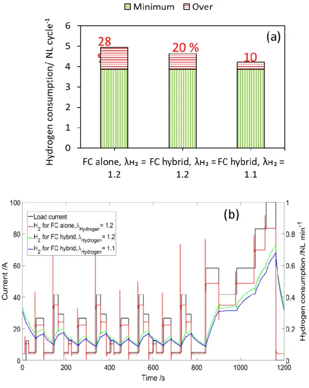
Fig. 1a presents the volume of hydrogen supplied during one cycle of FC-DLC as per various configurations, planned in the study. This shows that the maximum amount of hydrogen was supplied in the configuration of non-hybridized FC with 𝜆𝐻2= 1.2, which includes 28 % of overconsumption when compared to the minimum requirement detailed from Faraday's law and the cycling operation. This overconsumption included anticipation of 5 s, excess hydrogen stoichiometry and also the hydrogen supply associated with safety limit current density, here at 0.05 A cm-2. However, when the FC was hybridized with supercapacitors, the hydrogen
overconsumption was reduced to only 20 %, because time anticipation was not applied, and safety limit current density was always lower than the fuel cell current, since supercapacitors supply instantly the energy to the cycle demand. Thus, direct hybridization allowed saving hydrogen.
This hydrogen saving was further improved by reducing the stoichiometry of hydrogen, corresponding to only 10 % excess in case of hybridized fuel cell configuration. This reduction in hydrogen stoichiometry with non-hybridized fuel cell was not possible as the fuel cell was found to be starving in case of high current step demand. This once again highlighted the advantage of FC hybridization with SCs over conventional FC use.
Fig. 1b shows the hydrogen consumption during the FC-DLC testing conditions, over one cycle with respect to the current demand. For the fuel cell alone, the hydrogen supply changed 5 s before the current step, whereas, for the other two configurations, due to the presence of supercapacitors, the cell current was smoothed and thus so was the hydrogen consumption. Therefore, for hybrid configurations, the hydrogen consumption is less than that of the fuel cell alone. In the case of lower stoichiometry, the hydrogen consumption decreased, as evidenced in this Figure.
4.2. Effect on current and voltage profiles of non-hybridized or hybridized single fuel cell
Fig. 2 shows the current profile corresponding to the FC-DLC testing protocol, and the voltage response of the single cell, for different configurations such as FC non-hybridized or hybridized operation, along with varying hydrogen stoichiometry.
For a fuel cell alone configuration with hydrogen stoichiometry at 1.2, the current was totally supplied by the fuel cell, thus, it perfectly followed the cycle demand and the voltage response profile exhibits also sharp variations with time. For fuel cell hybrid configurations, the current and voltage profiles illustrate the smoothing effect of the supercapacitors. Interestingly, the current and voltage responses of the fuel cell followed each other for both
8
hydrogen stoichiometric conditions, with very comparable cell voltage at the highest current demands.
The fuel cell yield for the different configurations is presented in Figure 3. This yield is defined by the energy supplied by the fuel cell during the cycling operation in Wh over the fuel supplied to the fuel cell in normal liters (NL) of hydrogen [18]. This figure indicates that fuel cell alone at higher stoichiometry has the lowest yield when compared to the fuel cell hybrid configurations. By mere changing the excess in fuel – from 20% to 10% -, the yield of the fuel cell increased from 29 % to 43 % compared to FC alone, thus indicating clearly the advantage of the hybridization. The values given in Fig. 3, ranging from 1.05 to 1.5 Wh NL-1 of H2 have
to be referred to the enthalpy difference of the water/H2-O2 system, i.e. for 1 NL hydrogen, near
3.53 Wh NL-1.
4.3. Effect on long term operation.
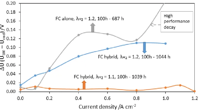
The results acquired from polarization curves at the beginning (after 100 h of operation) and the end of life for the three configurations are reported by difference in voltages (U) represented by U100 - Uend, in Fig. 4. For all the three configurations, the voltage response was
measured after 100 h of cycling operation for the single cell alone and after 687 h of operation for non-hybridized configuration – for which no power could be produced afterwards - and approximately after 1000 h in case of hybrid configurations: in this latter case long-term runs were deliberately stopped after that period.
For fuel cell alone configuration, the significant decay in performance and the MEA collapse after 687 hours, could be attributed to the increasing mass transfer over potential as the voltage response exhibits an accelerated degradation at high currents. The reasons for lower durability were further investigated. On the contrary, in hybridized configuration, change in hydrogen stoichiometry does not considerably affect the performance of the single cell. In fact, under high current demand, the cell was not fuel starved even with a low hydrogen stoichiometry – as indicated by the still fair voltage values, thus, lower cell degradation can be expected. Moreover, this indicates that the hydrogen excess might be further reduced but only in case of hybrid configurations.
4.4. Effect on FC electrochemical features in long-term runs
Interpretation of the spectra obtained by performing EIS technique after every 100 h of fuel cell operation for all the configurations as described in a previous paper [13] was carried out to
9
estimate the ohmic resistance, RΩ, the cathode charge transfer resistance, Rct, and the diffusion
resistance of the cathode, Rdc related to the Warburg placed in series with Rct in the cathode
circuit.
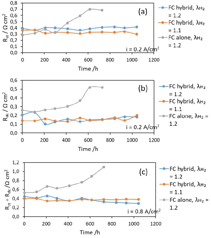
The ohmic resistance did not significantly change along the ageing runs, being all the time near 0.2 cm2 (data not shown). Fig. 5a shows the variation of the charge transfer resistance, Rct , and Fig. 5b shows for the diffusion resistance, Rdc over the overall period of the fuel cell
operation for different configurations and varying hydrogen stoichiometry. Both resistances were estimated separetely at 0.2 A cm-2. At high current density, e.g. 0.8 A cm-2, the contribution of the two resistances could not be differentiated, due to significant overlapping of the two loops, therefore the sum of (Rct + Rdc) was presented in Fig. 5c as a function of time of
fuel cell operation.
All the three figures, categorically indicate that the variation of hydrogen stoichiometry is not detrimental to the state of the health of the fuel cell, in case of hybridized configuration. For both stoichiometry conditions, the resistance data were very comparable. The 0.1 Ω cm2 deviation in Rct (Fig. 5a) is presumably due to the manufacturing conditions of the MEA and
also to the fitting accuracy in extracting values, and not to stoichiometric conditions. Moreover, the resistances remained very constant over the 1000 h long runs, expressing no significant degradation of the membrane-electrode assembly. However, in case of fuel cell alone configuration, these resistances present a noticeable increase in the last 200 h of operation, before its end of life. The resistances were approximately twice at the end of life, supposing degradation of both the catalytic layer and the gas diffusion layer. Thus, the lower durability of the fuel cell without hybridization appears expectable.
Along with the membrane resistances, hydrogen crossover and electrochemical active surface area (ECSA) of the catalyst were evaluated. The results of the hybrid configurations do not reveal any significant impact of hydrogen excess variation, as shown in Table 1. For hybridized configuration, these data are in perfect agreement with the time variations of the resistances, which shows no variations, regardless of hydrogen supplied. In contrast, the data with the non-hybridized cell, reveal significant variations, i.e. increase in hydrogen crossover and decrease in ECSA, directing towards lower durability of the FC alone.
10
Table 1: Hydrogen crossover and ECSA for FC hybridized at two hydrogen stoichiometric conditions and FC alone, at 100 h and at the end of the runs.
FC alone (100 h and 687 h) FC hybrid, 𝜆𝐻2= 1.2 (100 h to 1044 h) FC hybrid, 𝜆𝐻2= 1.1 (100 h to 1039 h) Hydrogen crossover /mA cm-2 18 % increase 2 % decrease 4 % increase ECSA /cm2 Pt cm-2 electrode 43 % decrease 21 % decrease 14 % decrease
4.5. Effect on GDL morphologies
As the membrane and the catalytic layer do not seem to be well informative, the investigations have been focussed on the macroporous layer (MPL) of the GDL in order to search for the evidence for the different durability of hybridized and non-hybridized configurations. The aged MEA were carefully dismantled for SEM observations of the GDL. The aspects of the MPL surfaces of the GDL are presented in Fig. 6, from the anode side (Fig. 6a, 6c, and 6e) and the cathode side (Fig. 6b, 6d, and 6f).
For all the three configurations, the images from the anode side revealed no noteworthy difference in surface aspect, neither hybridization nor the hydrogen stoichiometry impacted visibly the anode side of the MPL. For the cathode side, the pictures from the hybrid configurations do not reveal any significant change on the MPL surface. This supported that even the morphology of the GDL was not noteworthy affected by the hydrogen stoichiometric conditions. Besides, a striking difference in cathode MPL surfaces was observed with the non-hybridization configuration: as a matter of fact, without non-hybridization, the GDL surface exhibits significant loss of MPL. The MPL structure and adherence to the GDL seems to have been strongly affected by long term-cycling without supercapacitors. The clear degradation of the MPL substantiates hydrophobicity loss of the GDL and degrades water management capacity of the overall GDL: the likely occurrence of local flooding may further accelerate the MPL delamination.
Therefore, the minimum fuel cell voltage at the highest current density obtained during each cycle has been compared for interpretation (Fig. 7). Regular sudden voltage drops with an amplitude far larger than 100 mV, observed in the non-hybridized fuel cell voltage, appear highlighting flooding. Such sudden voltage drops were not visible in case of the hybridized fuel cell operations. The reason for the flooding in non-hybridized fuel cell operation was attributed to the low hydrogen flowrate during the low current density phase of the cycle. The amount of water actually produced in the high current density phase (from 850 to 1150 s) has to be partly
11
evacuated during the low current density phase, i.e. for the end of the cycle and the first minutes of the next one. The low amount of hydrogen during this low current density phase does not allow to evacuate this excess of water, which is undoubtedly partly in liquid phase. This excess water, thus, delaminates the MPL at the cathode, from the substrate layer along time and possibly erodes its structure, leading to loss of hydrophobicity, which consequently enhances the flooding. This directly impacts the FC performance and hence, reduces dramatically its durability.
One can notice that this phenomenon was not evidenced in the hybrid configurations because the fuel cell current was then smoothed, as well as the water production rate, due to the filtering effect of the supercapacitors. Along with that for hybrid configurations, a sharp voltage increase was observed after each characterization, in Fig. 7. This voltage increase is partially due to voltammetric investigations, particularly due to the low voltage periods in which slightly oxidized Pt clusters can be reduced back to metal Pt [13].
4.6. Effect on current and voltage profile of non-hybridized or hybridized fuel cell stack
The achievement in a single FC hybridized with SC on a long term experiment at a stoichiometric factor of 1.1, let us willing to check its feasibility with a FC stack: while defending for the performance and the durability of the system, it is very important to test the feasibility on a larger scale. The fuel cell test bench was therefore scaled up from a single cell to a stack of three cells. Cycling tests have been carried out for a few hours only.
Fig. 8a shows the effect of hydrogen stoichiometry on the response of the fuel cell stack, with or without its hybridization by the same SC combination. This figure indicates a similar response, when compared to single fuel cell operation, for the two hybridization configurations, however with voltage levels approx. 3 times larger. Invariably, it revealed no significant impact on the fuel cell stack operation. In addition, this figure does not show the behavior of the 3 cells without hybridization at lower stoichiometry since such operation could not be safely conducted: this indicated another advantage of hybridization.
Fig. 8b shows the current and individual voltage responses of the fuel cell stack to the testing protocol at the hybridized fuel cell configuration in case of reduced hydrogen stoichiometric condition 𝜆𝐻2= 1.1). This figure asserts the feasibility of this reduced condition without being
detrimental to even the individual cell of the stack. The performance of the individual fuel cell was also very comparable, which can be inferred from this figure. The unequal behaviour of fuel cell stack at high current density was observed. It is perhaps due to unevenness of the gas
12
distribution in the three cells as each individual cell might be fed at hydrogen stoichiometry slightly different from 1.1, such non uniform distribution of gas with this stack technology was already observed [19].
5. Conclusion
This investigation has been conducted in view to reducing the hydrogen feed in FC-DLC cyclic operation: while operating with low safety limit current (0.05 A cm-2), attempts were made to reduce the hydrogen stoichiometric factor from 1.2 to a lower level. The single cell with hydrogen stoichiometry as 1.1, cannot be studied without hybridization because the voltage of the fuel cell suddenly decreased too much during cycling at high current density. However, the single cell with hydrogen stoichiometry as 1.2, was operated until 687 h of cycling operation. This lower durability is mainly attributed to local flooding in the fuel cell, which is the consequence of the MPL loss from GDL, which was responsible for the hydrophobicity. The flooding in the fuel cell was identified by the sudden voltage drops at the high current density. The EIS data confirmed the increase in the diffusion resistance and LSV and CV data indicated towards increase in hydrogen crossover and decrease in active surface area, respectively. Finally, the MPL detachment and loss were clearly detected by the ex-situ SEM images.
In the case of the hybridized single fuel cell at both the hydrogen stoichiometric conditions, the performance of the configurations was very similar and both tests were voluntarily stopped after approx. 1000 h of cycling operation. EIS data confirmed that the reduction in hydrogen excess has no visible impact on the ohmic and transfer resistances, nor on the overall performance of the hybridized cell. The fairly flat profiles of hydrogen crossover and active surface area of the catalyst support the durability of the fuel cell. Thus, hybrid configurations do not reveal any significant modification, which contradicts the usual statement according to which operation at reduced hydrogen stoichiometry (down to 1.1) can be detrimental to the fuel cell core.
In addition, the hydrogen overconsumption was reduced from 28 % to 20 % by hybridization and could be further reduced to 10 % by reducing hydrogen stoichiometry during FC-DLC operation when 𝜆𝐻2 is reduced at 1.1.
To check the feasibility of the idea of reducing hydrogen stoichiometry on fuel cell stack, few hours of FC-DLC tests were done on different configurations. The results were similar to the single cell fuel cell operation. A variation in hydrogen stoichiometry produces no impact
13
on the hybrid fuel cell stack. To check the impact of reduced hydrogen excess on the performance of hybridized fuel cell and each cell in a stack, the voltage response on FC-DLC was measured. The voltage response of each cell in a stack was found comparable, even if not equal likely due to slightly uneven fluidic distribution.
In further work, currently in progress, the study extends to search the feasibility of such hydrogen excess reduction in the fuel cell stack for long-term runs.
Acknowledgments
This work was supported by the French PIA project «Lorraine Université d’Excellence», reference ANR-15-IDEX-04-LUE for the Ph.D. Grant allocated to Divyesh Arora.
14 References
[1] T.K. Mandal, D.H. Gregory, Hydrogen: A future energy vector for sustainable development, Proc. Inst. Mech. Eng. C 224 (2010) 539.
https://doi.org/10.1243/09544062JMES1774
[2] A portfolio of power-trains for Europe: a fact-based analysis, the role of battery electric vehicles, plug-in-hybrids and fuel cell electric vehicles, published 8 November 2010 http://www.fch-ju.eu/page/portfolio-power-trains-europe-fact-based-analysis.
[3] L.J.J. Janssen, Hydrogen fuel cells for cars and buses, J. Appl. Electrochem. 37 (2007) 1383. https://doi.org/10.1007/s10800-007-9347-8
[4] C. Davis, B. Edelstein, B. Evenson, A. Brecher, Hydrogen Fuel Cell Vehicle Study, American Physical Society Report, 2003.
[5] X. Hu, J. Jiang, B. Egardt, D. Cao, Advanced Power-Source Integration in Hybrid Electric Vehicles: Multicriteria Optimization Approach, IEEE Trans. Ind. Electron. 62 (2015) 7847. https://doi.org/10.1109/TIE.2015.2463770
[6] X. Lü, Y. Qu, Y. Wang, C. Qin, G. Liu, A comprehensive review on hybrid power system for PEMFC-HEV: Issues and strategies, Energy Convers. Manag. 171 (2018) 1273.
https://doi.org/10.1016/j.enconman.2018.06.065
[7] L. Xueqin, M. Xing, X. Yang, D. Liang, W. Min, D. Gu, et al., Dynamic modeling and fractional order (PID mu)-D-lambda control of PEM fuel cell, Int. J. Electrochem. Sci. 12 (2017) 7518.
https://doi.org/10.20964/2017.08.12
[8] L. Zhou, Y. Zheng, M. Ouyang, L. Lu, A study on parameter variation effects on battery packs for electric vehicles, J. Power Sources 364 (2017) 242.
https://doi.org/10.1016/j.jpowsour.2017.08.033
[9] B. Wang, J. Xu, D. Xu, Z. Yan, Implementation of an estimator-based adaptive sliding mode control strategy for a boost converter based battery/supercapacitor hybrid energy storage system in electric vehicles, Energ Convers. Manag. 151 (2017) 562.
https://doi.org/10.1016/j.enconman.2017.09.007
[10] B. Allaoua, B. Gasbaoui, Ant colony optimization applied on combinatorial problem for optimal power flow solution, Leonardo J. Sci. 8 (2009) 1.
[11] N. Benyahia, H. Denoun, M. Zaouia, T. Rekioua, N. Benamrouche, Power system simulation of fuel cell and supercapacitor based electric vehicle using an interleaving technique, Int. J. Hydrog. Energy 40 (2015) 15806.
15
[12] N. Sulaiman, M.A. Hannan, A. Mohamed, E.H. Majlan, W.R. Wan Daud, A review on energy management system for fuel cell hybrid electric vehicle: Issues and challenges, Renew. Sust. Energ. Rev. 52 (2015) 802.
https://doi.org/10.1016/j.rser.2015.07.132
[13] K. Gerardin, S. Raël, C. Bonnet, D. Arora, F. Lapicque, Direct coupling of PEM fuel cell to supercapacitors for higher durability and better energy management, Fuel Cells, 18 (2018) 315.
https://doi.org/10.1002/fuce.201700041
[14] G. Tsotridis, A. Pilenga, G. D. Marco, T. Malkow, European Commission, Joint Research Centre. EU harmonised test protocols for PEMFC MEA testing in single cell configuration for automotive applications. Publications Office E.U. Luxembourg, 2015, p 38.
https://doi.org/10.2790/342959
[15] S. Kim, S. Shimpalee, J.W. Van Zee, The effect of stoichiometry on dynamic behavior of a proton exchange membrane fuel cell (PEMFC) during load change, J. Power Sources 135 (2004) 110.
https://doi.org/10.1016/j.jpowsour.2004.03.060
[16] S. Shimpalee, U. Beuscher, J.W. Van Zee, Analysis of GDL flooding effects on PEMFC performance, Electrochim. Acta 52(2007) 6748.
https://doi.org/101016/jelectacta200704115
[17] F. Lapicque, M. Belhadj, C. Bonnet, J. Pauchet, Y. Thomas, A critical review on gas diffusion micro and macroporous layers degradation for improved membrane fuel cell durability, J. Power Sources 336 (2016) 40.
https://doi.org/10.1016/j.jpowsour.2016.10.037
[18] D. Arora, K. Gérardin, S. Raël, C. Bonnet, F. Lapicque, Effect of number of supercapacitors directly hybridized with PEMFC on the component contribution and the performance of the system, J. Appl. Electrochem. 691 (2018) 48.
https://doi.org/10.1007/s10800-018-1188-0
[19] Y. Chatillon, C. Bonnet, F. Lapicque, Heterogeneous aging within PEMFC stacks, Fuel Cells, 14 (2014) 581.
https://DOI.org/10.1002/fuce.201300105
16
Figure 1: Hydrogen consumption in the fuel cell depending on the operating and hybridization conditions. a) Hydrogen consumption and overconsumption per FC_DLC cycle in a single fuel cell; b) Hydrogen supply in a cycle with variable current load
17
18
Figure 3: Energy yield of a single hybrid fuel cell compared to fuel cell alone at different configurations.
19
Figure 4: Voltages obtained from polarization curves at the beginning (after 100 h of operation) and the end of life for the three configurations and are reported by difference in voltages (U) represented by U100 - Uend.
20
Figure 5: Time variations of the resistance of the MEA in long-term runs: Effect of
stoichiometry and hybridization state on a) charge transfer resistance Rct at i = 0.2 A cm-2,
21
Figure 6: SEM images for different aged GDLs for configurations of hybridized FC at λʜ₂ = 1.2 (a – anode side and b – cathode side), hybridized FC at λʜ2= 1.1 (c – anode side and d–
22
Figure 7: Variation of the minimum voltage in a cycle during long-term runs for FC alone or hybridized at different conditions.
23
Figure 8: a) Voltage and current profiles in the three- cell stack at different configurations; b) Voltage profile of individual cells in the hybridized stack at λʜ2 = 1.1.
24 Graphical Abstract
Hydrogen saving