The Design and Construction of a Modular Force Control Actuator
byMichael B. Wittig
Submitted to the Department of Mechanical Engineering in partial fulfillment of the requirements for the degree of
Bachelor of Science in Mechanical Engineering at the
MASSACHUSETTS INSTITUTE OF TECHNOLOGY June 1996
© Michael B. Wittig, MCMXVI. All rights reserved.
The author hereby grants to MIT permission to reproduce and distribute publicly paper and electronic copies of this thesis document in whole or in part, and to grant
others the right to do so.
A uthor ...
Certified by...
... ...
*
...Department of Mechanical ngineering Jay 10, 1996
Gill A. Pratt Assistant Professor of Rectrical Engineering and Computer Science
Thesis Supervisor
Accepted by...
Professor Peter Griffith
viA3SAcHUSETTS INSTITU E Chairman, Department Comnmitt of Undergraduate Theses
OF TECHNOLOGY
The Design and Construction of a Modular Force Control Actuator by
Michael B.Wittig
Submitted to the Department of Mechanical Engineering on May 10, 1996, in partial fulfillment of the
requirements for the degree of
Bachelor of Science in Mechanical Engineering
Abstract
This thesis describes the design, construction, and performance of a modular force control actuator, incorporating an electric motor, a gearbox, a ball screw acting as part of the transmission, and springs as the series-elastic elements. The approach of integrating all of the components necessary to perform force control for one degree of freedom simplifies robot design, construction, and debugging. The constraints initially placed on the design are discussed, and full explanations are given as to why each of the major components in the system were chosen for use in this particular application. Finally, a qualitative discussion of the prototype's performance is given, along with response data to a square wave and a sine wave in commanded force.
Thesis Supervisor: Gill A. Pratt
Acknowledgements
I thank my advisor, Gill Pratt, for his patience, encouragement, and the many excellent
suggestions he has given me during this project and many others.
I thank the Leg Lab head RA, Jerry Pratt, for the time he spent with me to test and
analyze the actuator, in addition to the continuous support he provided me throughout my work at the Leg Lab.
Thanks also to Peter Dilworth for lending his incredible mechanical judgement at times when traditional calculations were questionable, and to Hugh Herr, for the comic relief he endlessly provides to all of us.
Contents
1 Introduction 7
1.1 What Force And Position Control Are And Why They're Important... 7
1.2 The Problems That Force Control Actuators Can Cause... 7
1.3 Summary Of Thesis Contents ... 8
2 Design Requirements 9 2.1 Introduction ... . 9
2.2 Mimicking Nature ... 9
2.3 The Zero Force Requirement ... 10
2.4 Size, Weight, And Power Output Specifications ... 10
2.5 Modular Construction ... 11
2.7 Practical C oncerns ... 12
3 Design Implementation 14 3.1 In troduction ... 14
3.2 L inear V s. R otary ... 15
3.3 The Series-Elastic Element ... 18
3.4 T he Sensors ... . . 2 1 3.5 The Motor And Gearbox ... 22
3.6 T he B all Screw ... 23
4 Prototype Actuator Performance 25 4.1 Introduction ... 25
4.2 Qualitative Statements On The Prototype's Performance... 25
4.3 Data Collected During Square Wave And Sine Wave Inputs... 26
5 Conclusions 29 5.1 Review Of Thesis... 29
5.2 Foreseeable Improvements In The Prototype Design... 29
A P arts L ist ... 3 1 B Custom Parts Drawings ... 32
List of Figures
2-1: Schematic of what the modular design of the actuator was to include, and how the elastic element required to mimic the tendons and ligments of
animals was often used in previous designs to measure the output force... 10
2-2: A picture of Spring Therapod's rear leg and tail section. Note how the leg is used not only for the leg geometry, but also to mount and distribute actuator components. Also note the actuator differentiation for different task s... 12
3-1: The com pleted actuator prototype... 14
3-2: Connecting a linear actuator to a rotary joint is relatively straightforward... 15
3-3: The difficulties inherent of converting rotary actuation to linear actuation... 15
3-4: How the prototype actuator's springs are implemented in a linear manner... 17
3-5: Schematic showing a possible, but complex, method of using pre-compressed linear compression springs as the elastic element in rotary applications w ithout backlash... 17
3-6: A graph of force vs. displacement of the gastrocnernius tendon of a Australian wallaby (similiar to a small kangaroo). The area between the curves represents the energy lost to heat during one stretch cycle, while the area underneath the lower curve represents the energy recovered when elastic recoil occurs. Note that the linearity of the curves suggests that helical springs would probably make a reasonable substitute for tendons when the intention of the robot is to mimic animal locomotion. From [1]... 18
3-7: Diagram showing the origin of the stress concentration in extension springs and a way to reduce it. The stress at A is caused by both axial and bending forces, while the stress at B is mainly torsion. Sections (a) and (b) show a typical spring, while (c) and (d) show a spring improved by reducing the m om ent arm at B . From [6]... 19
3-8: The three forms of linear potentiometers researched for use in the actuator design. The low cost potentiometer design wears out quickly due to the offset D of the mounting tab from the resistive slide element, which produces a net torque that destroys the short linear bearing surface. The expensive military-style design is much smoother and more reliable due to concentric mounting of the wiper shaft and the resistive wire coils, but it is heavy due to the stainless steel case and shaft. The unique design from Novotechnik minimizes the components in the system for the lowest weight, and the resistive strip on which the wiper travels in laser cut to m aintain linearity along its length... 21
3-9: How the cheap motor chosen for the actuator could produce a much higher power density (albeit with much more heat) in comparison to
expensive m otors... 22
3-10: A large picture showing some of the mechanical details of the actuator not discussed previously... 24
4-1: Current saturation was a constant problem during testing, as may be seen ab ove... 2 6 4-2: How well the actuator responded to a square wave in force command... 27
4-3: Current saturation caused instability when the the actuator was force commanded, as may be seen by the vibrations on Figure 4-4 corresponding to the saturation area shown above... 28
4-4: Response of the actuator when force commanded to follow a sine wave in p u t... 2 9 B-1: Overview of the custom part placements within the design... 32
B-2: Part drawing for the ball screw modifications... 33
B-3: Part drawing for the ball screw to bearing adapter... 34
B-4: Part drawing for the spring mover... 34
B-5: Part drawing for the motor mount plate... 35
B-6: Part draw ing for the side plates... 35
B-7: Part drawing for the potentiometer wiper mount... 35
B-8: Part drawing for front support plate... 36
B-9: Part drawing for potentiometer mount plate (not shown in B-1, mounts between the two spring clamps on the lefthand side)... 36
Chapter
1
Introduction
1.1 What Force And Position Control Are And Why They Are
Important
Force and position control are feedback methods used when robots interact with their environment. Many situations during such an interaction may require that the robot perform some sort of correction for any errors made in executing the task it was given. If a robot is told to swing its arm 90 degrees to the left and it ends up swinging it 91 degrees because it failed to take its own inertia into account, a control scheme may be used to correct the situation. In such an example, position control would be applicable because the robot would need correcting for its positioning mistake. In a task involving the application of forces by the robot upon its environment, such as while drilling, cutting, or just touching an object, force control is more applicable. Both systems obtain
information via sensors about how well the robot is performing its task and use actuators to apply corrections. Without a control scheme in place, the robot is not informed when it makes errors during the execution of its task, with the result often being that the task accomplished doesn't meet expectations of the robot's instructor.
1.2 The Problems That Force Control Actuators Can Cause
Oftentimes, a control scheme is in place and the robot still manages to make errors during its task execution. This may occur because the robot's perception of the environment is unrealistic due to incorrect sensor information. It may also be caused by the actuators animating the robot in a way that that the sensors are not aware of.
Since both sensors and actuators are necessary to use a control scheme, they are sometimes combined. A position controlled actuator and sensor combination is
commonly known as a servo, while a force controlled actuator and sensor combination is named simply a force control actuator.
Since both the sensor and actuator exist in either type of unit, it is often within these units that mechanical and electrical problems related to the control scheme arise. This thesis examines the design of a modular type of actuator-sensor unit designed to reduce the likelihood of encountering such problems, as well as to make them easier to deal with
1.3 Summary of Thesis Contents
The contents of this thesis is as follows:
Chapter 2 covers the design requirements conceived for an actuator to be used in the
legged robots of our lab.
Chapter 3 describes what design choices were made for the prototype actuator and why. Chapter 4 provides data on the performance of the prototype actuator and a qualitative
analysis of it.
Chapter 5 presents the insights gained from the prototype and suggestions for future implementations.
Appendix A supplies the off-the-shelf parts list for the prototype actuator.
Appendix B supplies the parts drawings necessary to build the custom parts of the
Chapter 2
Design Requirements
2.1 Introduction
This chapter outlines the basic specifications and concerns that needed to be kept in mind during the initial actuator design. Compromising between these items was where a majority of the design effort went during the course of this thesis. The choices made based on these requirements are explained and justified in chapter 3.
2.2 Mimicking Nature
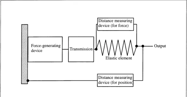
Since most of the robots built in the Leg Lab mimic the functionality of natural creatures in trying to walk, it would make sense to copy some of the features nature built into these creatures to carry out the task. One of the most important differences between an animal and the typical industrial robot is the ability to absorb shock. Because of the elastic nature of ligments and tendons, an animal may swing a limb into a rigid object without causing damage to itself; an industrial robot, however, would likely cause significant damage to itself by doing so because of its rigid transmission and linkages. The elastic properties of animal tendons and ligments also allow the storage of energy, which translates into the ability to exert forces greater than the muscle alone could exert. By incorporating an elastic element into the actuator design, both of these advantages may be gained. An actuator using an elastic element in series with its output (like animals) is said to work on the principle of series-elastic actuation [4]. Because all of the current robots in our lab work using this principle, it was important that the actuator included an elastic element in series with the output. Figure 2-1 illustrates how the elastic element was also expected to be used for measuring the force exerted by the actuator.
Distance measuring device (for force)
Force-generating .r.nmiss--- Output device Transmission
Elastic element
Distance measuring E ' device (for position
Figure 2-1: Schematic of what the modular design of the actuator was to include, and how the elastic element required to mimic the tendons and ligments of animals was often used in previous designs to measure the output force.
2.3 The Zero Force Requirement
A major drawback of previous designs incorporating springs was that the point of zero
force, where the robot sensed no torques on its limbs, would drift. On Spring Turkey [2], this was attributed to periodically over-stretching the extension springs used to sense forces on the limbs. Because of the trouble this situation caused in making Spring Turkey walk on a consistient basis, eliminating it on the new actuator design was a priority.
Another more likely problem to occur in sensing actuators is that between the output and the sensor, conditions exist that prevent small force changes from registering at the sensor. Friction in the bearings and transmission components between these two points are often the main causes, but others exist. For example, using a compression spring in series with the output that begins precompressed (in order to eliminate play due to spring tolerances) causes a force equal to the precompression to be required before the sensor is likely to feel anything. This can be overcome by using two springs precompressed against each other, but such a design adds extra weight. All of these potential compromises needed to be accounted for during the actuator design.
2.4 Size, Weight, and Power Output Specifications
The power required of the actuator was not specifically set at the beginning of the design process. Instead, the weight and size of the actuator were constrained to roughly match
the actuators already installed on one of the lab robots, and then the power available within those constraints was maximized. This was done because the size and weight of
the robot were typical of the robots built in the leg lab. Because the robot was
underpowered, however, the 30 W power output of its motors was used as the minimum allowable value for the new actuators.
2.5
Modular Construction
The main goal of the actuator design was to integrate the components required to do force and position control for one degree of freedom into a single package. Ideally, this would include the force-generating component (typically a motor), a transmission, a force sensor, a position sensor, an elastic element, and an electronics control package. The two main advantages of doing so are as follows:
Robot design simplification- By integrating the components needed for each degree of
freedom into a single frame, robots with many degrees of freedom become much easier to design and construct. Issues such as geometric constraints, sensor mounting,
spring-to-motor sizing, and proper transmission ratios do not need to be dealt with on an individual joint basis. Instead, only a structural "skeleton" of the robot would need to be designed, and then the actuators could be added to control one degree of freedom each.
Easier debugging of robotic functions- A common problem faced by robotic
researchers is the inability to separate the causes for failure when a robot does not perform properly. Sometimes it could be the algorithm used to control the robot, but often the functioning of the mechanical and electrical components is questioned. Because both the mechanical and electrical systems consist of many individual components, testing each one for proper functionality can be tedious and time-consuming. By integrating all of the components into a single frame that may easily removed from the robot, suspected actuator packages may be replaced with spares. Additionally, since only one design of the actuator exists, and its characteristics known in detail, finding the problem in a faulty actuator would become much more straightforward.
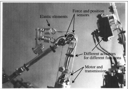
The main disadvantage of a modular actuator design is that it is unlikely to be optimal for every degree of freedom on a particular robot. In a walking robot, the hip, knee, and ankle joints all require a different range of torques during regular locomotion for typical leg geometries borrowed from nature. Ideally, each actuator would possess the minimum size, weight, and sensor accuracy to meet the velocity, torque, and control requirements of the joint. Additionally, a modular actuator uses a separate frame apart from the robot skeleton to carry loads, while a weight-optimized design could make use of the strength of the skeleton. For example, Figure 2-2 shows how the skeleton of Spring Therapod, a robot under development by Peter Dilworth at MIT, is utilized to mount the various actuator components. In this robot, the skeleton which provides the leg geometry also doubles as the frame for the sensors, springs, and the motor-transmission package, thereby saving weight and improving the weight distribution of the leg.
Figure 2-2: A picture of Spring Therapod's rear leg and tail section. Note how the leg is used not only for the leg geometry, but also to mount and distribute actuator components. Also note the actuator differentiation for different tasks.
The design of the actuator presented in this thesis did not include the integration of the electronics control package, which is currently under development by Gill Pratt at MIT. Once it is completed and installed, only the desired force (or position) will need to be signaled to the actuator.
2.6 Practical Concerns
Other constraints placed on the design were as follows:
Electrically powered- Our lab has both pneumatic and hydraulic supply lines. However, most places we would want to take our robot for demonstration do not. Since one of the current goals of our lab is to produce a portable autonomous robot, it was decided that electric power was a necessity. A drawback to this constraint is that the power density among typical electric motor systems is approximately one-fifth that of a hydraulic system once a suitable transmission is included. This is not a theoretical limit, but rather what has been practically accomplished in the past.
Low cost- Robots often have several degrees of freedom, and each requires at least one
actuator. Legged robots tend to need many actuators because of this. For example, a hexapod robot would require three degrees of freedom per leg, totaling 18 actuators minimum. Therefore, the cost of each actuator was a critical value.
Extensive use of standardized parts- The use of standardized, off-the-shelf parts was a
constraint partially due to keeping the cost of the actuator down. It was also important for reducing the time it would take to construct an actuator (and hence the robot), as well as to allow the testing of various versions of each part to determine the best one for the job. For example, the linear bearings used in the prototype were changed several times to find the material that possessed the lowest coefficient of friction against carbon fiber tubes.
Ease of manufacturing custom parts- Some components inevitably must be made from
scratch on every construction project. For this actuator, it was decided that the manufacturing processes required to shape the material should be available in a basic machine shop. Also, the use of exotic materials that would require extreme care in processing, such as ceramics (too brittle) and titanium (bad machinability) was ruled out.
Availability of parts and materials- The lifespan of a typical research robot is short in
comparison to its industrial counterpart. In the Leg Lab, robots tend to have a design and construction cycle of only a year. Therefore, parts requiring long lead times to obtain could significantly affect the progress on the robot's design, since dimensions and specifications of other components may depend on those parts arriving for tests and measurements. Also, if the parts break during the use of the robot, the research for which the robot was intended would also suffer from waiting for a replacement to arrive. For example, the choice of the ball screw used in the design of the prototype was determined mainly by this factor. Two foreign companies, Schneeberger and Koyo, both had ball screws over three times smaller in diameter than the U.S. company that ended up supplying the ball screws, but their leadtimes were over three months.
Chapter 3
Design Implementation
3.1 Introduction
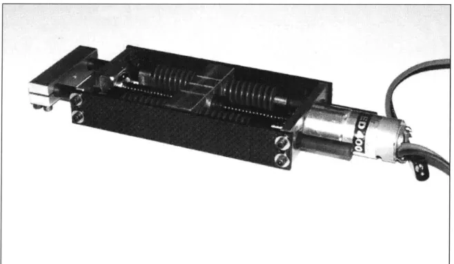
This chapter describes the specific design and construction of the prototype modular force control actuator, shown in Figure 3-1. The prototype used a low cost electric motor, single-stage gear reduction, and a ball screw to generate linear forces. The series-elastic element consisted of four chrome vanadium compression springs. Force and position were sensed using precision linear potentiometers. The compromises made among the design requirements and constraints to produce this design are discussed in detail in the following sections.
Figure 3-2: Connecting a linear actuator to a rotary joint is relatively straightforward.
3.2 Linear vs. Rotary
The actuator was designed to have a linear output. The reasons for this are numerous:
Linear-to-rotary conversions are easy, but rotary-to-linear conversions are not
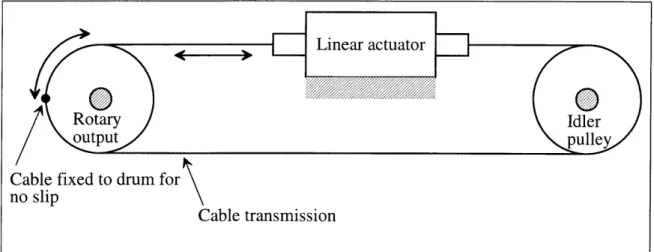
As shown in Figure 3-2, it is a relatively straightforward task to attach a linear actuator to a rotary joint. A drum is attached to the limb intended for rotation, and then cable is wrapped around the drum and connected to the output of the actuator. Bidirectional actuation requires that an idler pulley be used.
Figure 3-3 reveals that the inverse configuration is more difficult to build into the skeleton of the robot. Linear bearings must be used to stabilize the final output shaft, and the cable must attach to the center of the shaft on both sides to prevent a torque on the shaft. Additionally, the shaft must have a passage cut into it to allow the cable to exit onto the idler pulley, which also must fit into the passage. To avoid this, two output shafts may be used to prevent a cluttered centerline, but it doubles the number of parts required on the robot skeleton. The design simplifies considerably for unidirectional applications, but most of the robots in our lab require bidirectional actuation.
Linear
bearings-Idler pulley
Note that in order t torque on the outpu cable must run alor
Rotary Actuator o prevent a 0 t shaft, the g its centerlin~e! Cable transmission Rotary output
Cable fixed to drum for no slip
Cable transmission
F-Linear actuator
DIdler plulley
Note that in both of these cases, it was assumed that cable would be used. This is because other linkages, such as racks, add backlash to the connection between the joint and actuator. Because the actuators were planned to be modular, the force and position sensors and springs are within the actuator itself. Hence, backlash in the connection between the limb and actuator would ruin the force and position sensing of the the system because the limb (or whatever was attached to the output via the connection) would be free to move distances corresponding to the backlash without the sensors detecting anything. Backlash is permissible in the transmission because it occurs before the force sensing and position sensing elements.
Materials are more efficient in tension than in torsion
Another advantage of a linear actuator is that the output is in tension (when cables are used), while a rotary actuator's shaft is in torsion. For a given piece of material, failure will occur first in torsion rather than in tension. This is a very broad generalization, but the rationale is as follows:
For torsion, the maximum shear stress developed in a shaft when a torque T is applied is:
Tmax - 16T (3.1)
The maximum normal stress developed on a member in pure tension when a force F is applied is:
Umax = avg= 4F (3.2)
nD2
Three other relations are required to relate r and o for comparison:
a= EE, (3.3)
where E is the modulus of elasticity of the material used, and e is the strain,
t = Gy, (3.4)
where G is the modulus of rigidity and y is the shear strain, and
E= 2G(l +v), (3.5)
where v is Poisson's ratio, equal to the negative of lateral strain over axial strain. Substituting equations 3.1 through 3.4 into equation 3.5 yields:
F-=8(1+ v). T(3.6)
Since Poisson's ratio is positive for almost all materials, equation 3.6 demonstrates in a crude way why tension is preferable to torsion. The derivation above is useful because the relationships are familiar and they lend intuitiveness to the understanding. A more rigorous and involved approach uses energy relations and may be found in [6].
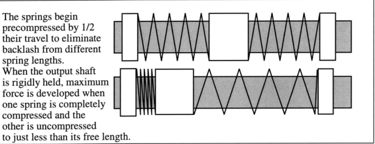
The springs begin precompressed by 1/2 their travel to eliminate backlash from different spring lengths.
When the output shaft is rigidly held, maximum force is developed when one spring is completely compressed and the other is uncompressed
to just less than its free length.
Figure 3-4: How the prototype actuator's springs are implemented in a linear manner. the prototype actuator and the one it was intended to replace. The motors on Spring Turkey had a maximum power output of 30 W, which was transmitted through a 1/2"
shaft in torsion. The prototype had a maximum power output of 40 W, and transmitted force using cabling which was less than 1/16" in diameter. Note that torsion-transmitting shaft attachments such as set screws, clamps, keys, and pins also increase the diameter of required, and this was also a cause for the large difference in diameters.
A linear output made it easier to use compression springs
Compression springs were used in the prototype design, and the rationale for this will be given in the next section. Incorporating them into the actuator was much easier if the output was linear, because they could be placed in-line with the output and preloaded to prevent backlash. The prototype's linear spring setup is shown in Figure 3-4.
Figure 3-5 shows a rotary design that would use compression springs. Note that
'#7 Output pulley Input pulley Plates rigidly mounted to large output disk
Figure 3-5: Schematic showing a possible, but complex, method of using precompressed linear compression springs as the elastic element in rotary applications without backlash.
although it was possible to build it, the design was unnecessarily complex and therefore a linear version was preferred.
A linear output allowed the use of a ball screw as a transmission component
This was perhaps the most important factor in the decision to use a linear output. Since ball screws convert rotational motion into linear motion, a linear output eliminates the need to convert the linear motion back to rotational. The advantages of using a ball screw as part of the transmission on the actuator are discussed in section 3.6.
3.3 The Choice of The Series-Elastic Element
It was decided to use four chrome-vanadium die springs as the elastic component of the actuator. The following reasons provide justification for the decision:
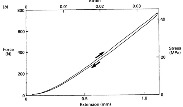
Animal tendons have surprisingly linear spring rates
As Figure 3-6 shows, animal tendons have a very linear spring rate and act very similiar to off-the-shelf helical springs. Thus, it seemed reasonable to use them as the elastic elements of the modular actuator, because most of the robots built in our lab attempt locomotion in the same manner that animals do.
(b) C 800 f 0.01 Strain 0.02 0.03 6001 Force (N) 400 200 Al 0 0.5 1.0 Extension (mm) '40 20 Stress (MPa) 0
Figure 3-6: A graph of force vs. displacement of the gastrocnemius tendon of a Australian wallaby (similiar to a small kangaroo). The area between the curves represents the energy lost to heat during one stretch cycle, while the area underneath the lower curve represents the energy recovered when elastic recoil occurs. Note that the linearity of the curves suggests that helical springs would probably make a reasonable substitute for tendons when the intention of the robot is to mimic animal locomotion. From [1].
Compression springs have important advantages over extension springs
After the decision to use helical springs was made, it was necessary to choose beween extension and compression springs. Compression springs were chosen because of two main advantages.
First, a compression spring reach the end of its travel when all of its coils are stacked up. Thus, the compressed form acts more like a tube in compression, and the same magnitude of force that was required to compress the spring totally is not sufficient to yield the material in this form. However, an extension spring does not have such a means to prevent over-extension. The result is that a short pulse of extreme load can
permanently deform the spring. This was a problem on previous robots that measure spring extension to derive the forces present, such as Spring Turkey, because it caused the zero-force calibration of the spring-potentiometer system to drift [2].
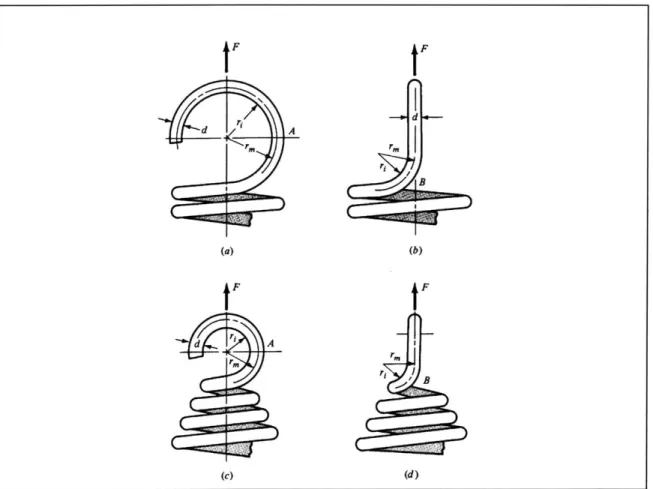
Second, although similiar coils of both types of springs store the same amount of energy for the same absolute distance traveled, almost all extension springs have a hook attachment. The problem with the hook attachment is that the sharp bend where the wire forming the coils becomes the hook creates a stress concentration. Figure 3-7 shows this problem and also a partial remedy for it, which involves reducing the coil diameter to decrease the moment arm the coil has on the bend. Tests have shown that the stress
t F d A (a) IF d A Fm (c) F B (b) IF ri / B (d)
Figure 3-7: Diagram showing the origin of the stress concentration in extension springs and a way to reduce it. The stress at A is caused by both axial and bending forces, while
concentration can be approximated by:
K = , (3.7)
where rm is the mean coil diameter and r is the inner coil diameter. Therefore, the inverse of equation 3.7 is the expected reduction in energy density for the spring due to the stress concentration.
The instability inherent in a compression spring would normally be a disadvantage in comparison to an extension spring. However, because the the actuator design had carbon
fiber tubes running through the springs, this was not a problem.
Another issue of interest once a helical compression spring was chosen was the optimum sizing of the spring. This was done based on two criteria, the diameter and the length. The optimum diameter was determined by looking at what would provide the highest energy storage density. In a spring, the energy density, ED, is provided by the integral of the spring rate equation divided by the mass m, or
ED = kx2 (3.8)
2m'
where k is the spring constant, and x is the displacement of the spring. The spring rate for helical springs is
k d G (3.9)
8D 3N'
where d is the spring wire diameter, D is the coil diameter, N is the number of active coils, and G is shear modulus of the spring material. Thus, the energy density varies heavily with d4/D3, meaning that the wire diameter should maximized while the coil diameter should be minimized. Since it was a design requirement to use off-the-shelf components, only the coil diameter could be chosen.
The length of the spring was determined by first laying out the transmission
components on a CAD program, and then finding the longest springs that would fit into the design. This was done because the short spring travels on previous designs produced a low force detection sensitivity, since the potentiometers used to measure the spring displacement moved only a small amount. Although actuator bandwidth would be lowered due to the decreased spring rate, it was believed that force sensing was a more important issue [4].
Lastly, the choice of chrome vanadium as a spring material was based on the recommendation of the spring manufacturer and design literature [6]. Although other materials have a higher yield strength, the excellent fatigue and shock resistance of
chrome vanadium made it desirable to keep force detection consistient. Chrome silicon is ideal in both respects and is often used for aircraft springs, but the design requirement of low cost and easy availability ruled it out.
3.4 The Sensors
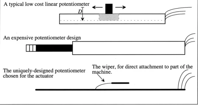
Finding the appropriate sensors for the actuator turned out to be extremely difficult. Because both the springs and the actuator output moved in a linear fashion, linear potentiometers were the easiest type of sensor to implement. The different versions investigated for use with the actuator are shown in Figure 3-8. Typical low cost linear potentiometer designs incorporate a plastic mounting tab that is offset from the resistive strip, which induces a net torque that causes excess wear on the bearing surfaces. This leads to an early failure of the sensor, as well as rapid degradation of consistiency and performance. Since consistient force sensing was made a priority, this design was deemed unacceptable. The military-style potentiometer proved very consistient and had low friction, but the stainless steel shaft and case, combined with the miniature wire coil used as the resistive element, made the design very expensive and heavy. The unique design offered by Novotechnik was inherently more difficult to incorporate into the actuator, since it relied on the host machine to keep the wiper and and resistive element properly spaced. The wiper was unfortunately also very delicate and needed to be protected by the actuator's structure. These concerns were greatly offset by the excellent linearity, and low weight of the sensor. Although a simple resistive strip similiar to the
A typical low cost linear potentiometer
An expensive potentiometer design
The wiper, for direct attachment to part of the
The uniquely-designed potentiometer machine.
chosen for the actuator
Figure 3-8: The three forms of linear potentiometers researched for use in the actuator design. The low cost potentiometer design wears out quickly due to the offset D of the mounting tab from the resistive slide element, which produces a net torque that destroys the short linear bearing surface. The expensive military-style design is much smoother and more reliable due to concentric mounting of the wiper shaft and the resistive wire coils, but it is heavy due to the stainless steel case and shaft. The unique design from Novotechnik minimizes the components in the system for the lowest weight, and the
ones found in the low cost potentiometers was used, linearity was excellent due to an ingenious manufacturing process: the manufacturer used a laser to remove resistive material in varying widths in order to keep the resistance constant across the length of the sensor. The linearity on the shorter potentiometer sizes was 0.25%, while slightly longer sizes posessed about 0.1% linearity, so a longer size than necessary was used. Keeping the proper distance between the wiper and the strip was extremely critical for the sensor to operate smoothly, so the sensor was measured and incorporated into the CAD model of the actuator to ensure correct dimensions.
3.5
The Motor and Gearbox
The motor chosen for the design was surprisingly cheap at only $11, especially given that the transmission components summed to around $200. Yet, after comparison to over 60 motors based on their output torques, rpm's, size, weight, and cost, it was the front-runner. The reasons were as follows:
It had an extremely high energy density for its size
The reason for this is rather simple intuitively: it would get extremely hot from its inefficiency, but the amount of power going to the motor was so large that the output was still substantial. Durability of course suffered in this design, but since robots are
relatively short-lived creations, and the low cost of the motor made it easy to replace, it was a deemed a good compromise.
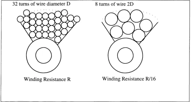
The trick employed to dramatically increase its power output over other motors of better quality was the use of large electric currents, as shown in Figure 3-9. Power dissipation rose with the square of the current increase, which accounted for the higher
32 turns of wire diameter D
Winding Resistance R
8 turns of wire 2D
W
Winding Resistance R/16
Figure 3-9: How the cheap motor chosen for the actuator could produce a much higher power density (albeit with much more heat) in comparison to expensive motors.
temperature of the motor in comparison to others. The rate of heat transfer by natural convection off its casing increased with the temperature differerence, however, so active cooling wasn't necessary.
The power output was in the range of the motors used on previous robots
The motor had a maximum power output of 40 W, which was 25% greater than the motors used in previous robots. This was done on purpose, since Spring Turkey [2] was deemed slightly under-powered.
The size of the motor made it easy to mount into a low-profile design
The diameter of the motor corresponded to the maximum thickness of the other actuator components, which streamlined the design.
An excellent gearbox was readily available for the motor
A single-stage ball bearing-supported gearbox with hardened gears and shafting was
readily available from the supplier of the motor. The gearbox was necessary to reduce the speed of the motor to a speed that the ball screw could tolerate, which was specified by the ball screw manufacturer as less than approximately 4000 RPM.
3.6 The Ball Screw
A ball screw was chosen as the final stage of the transmission for four main reasons.
First, the 0.125" pitch of the ball screw provided a tremendous reduction ratio. For example, cabling the output of the ball screw to a 2" diameter pulley provides a reduction ratio of 50 to 1 between the input of the ball screw and the pulley.
Second, the "play" or backlash in the ball screw was on the order of 3/1000", or about
0.17 degrees of rotation from a 2" pulley. Gears of 16 to 48 pitch, the typical diametrical
pitch range used in previous lab designs, have 1.5/1000" on average of backlash per gear stage when new, and this increases with age. To meet the 50:1 reduction of the ball screw using a 2:1 reduction per gear stage, a geartrain would typically have a composite error of
11/1000" minimum.
Third, although the efficiency of the ball screw is only 90%, this is quite high for the amount of reduction it provides. The geartrain mentioned above would have an
efficiency around 89% assuming the gears mesh at 98% efficiency. This doesn't include bearing losses.
Finally, the ball screw reduced the backlash of the single-stage gearbox by its reduction ratio, making its contribution to the output backlash negligible.
The center of the ball screw was drilled out to reduce its rotational inertia and weight, since the ball screw was oversized to begin with. To prevent the ball screw from
becoming too brittle during heat treatment due to the exposure of inside of the screw to the hot salts, the hole was plugged.
The following page is Figure 3-10: A large picture showing some of the mechanical details of the actuator not discussed previously.
Clamps locked to
Clamps locked to
the carbon fiber shafting
5.9:1 Gearbox
Spring mover
Moves relative to the shaft when forces are applied.
Carbon fiber side plate Shaft and spring mover travel at the same rate 3/8" Carbon fiber when no output forces or accelerations are present. tubing
40 W Electric motor
Not shown: linear potentiometers Output
Chapter 4
Prototype Actuator Performance
4.1 Introduction
This chapter describes the qualitatitively the performance of the prototype actuator, and presents useful data for analysis, including plots of the actual vs. desired torque, the torque derivative, and current traces for both square wave and sine wave force
commanded input functions. Because this thesis is mainly concerned with the design aspects of the actuator, a detailed analysis of the data will not be presented. Foreseeable design improvements based on the qualitative observations of this chapter will be recommended in the next chapter.
4.2 Qualitative Statements on The Prototype's Performance
The actuator performed well given its prototype status. Two deviations from the initial design were implemented during testing. The first was the replacement of the springs with new ones having about half the spring rate of the old ones. This was done mainly because the actuator test equipment available at the time of construction was only capable of delivering five amps of current, which was not enough for the motors to develop the torque required for complete spring compression. Second, the motor was replaced with a rewound version estimated to run on double the nominal voltage, but current saturation was still present.
The current limitation was a significant problem in trying to judge the performance of the actuator, since the motor caused current saturation almost continuously as Figures 4.1 and 4.3 demonstate. Still, even with the weak springs and low current, the actuator was estimated by Jerry Pratt to achieve a bandwidth of approximately 30 Hz. This was about the same as Spring Turkey's [2] actuators, which suggested that the new actuator was as capable as those used in previous designs. As Figures 4.2 and 4.4 show, the actuator managed to follow the the commanded forces relatively well despite the current limitation.
The sensors worked better than expected, and proved very consistient. Neither the sensors nor the springs seemed to contribute to any noticable drift in the zero force
shafts and the linear bearings, however, and this impeded the actuator's ability to
smoothly simulate zero force at its output. This was probably because the three parts that hold linear bearings along the same axis were machined on separate occasions.
4.3 Data Collected During Square Wave and Sine Wave Inputs
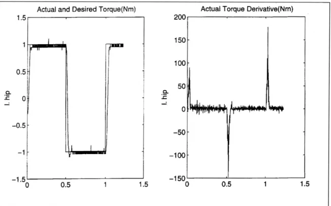
The following diagrams illustrate the data collected from the actuator during testing using Spring Turkey's test setup [2]. The position of the output was set to 0 by clamping it to the frame of the actuator. Figures 4-1 and 4-2 illustrate the response when a square wave is used as the input force command, while Figures 4-3 and 4-4 show the response to a sine wave input.
Amps Position (rad)
5 1 4 0.8-3 0.6-2 0.4-1 0.2-00 -1 -0.2 -2 -0.4--3 -0.6-.-4 -0.8-0 0.5 1 1.5 0 0.5 1 1.5
Current saturation was a constant problem during testing, as may be seen Figure 4-1:
CL-1.5 1 0.5 0 .IM
Actual and Desired Torque(Nm) Actual Torque Denvative(Nm) 200 150 100 50 0 -0.5 -50 .1 100--150' 0 0.5 1 0.5 -1.5' 0 1.5 1
Figure 4-2: How well the actuator responded to a square wave in force command.
Amps Position (rad)
51 4 0.8-3 0.6-2- 0.4-1 - 0.2-0 0 -1 - -0.2--2- -0.4--3- -0.6--4- -0.8--5 - -' -1 ' 0 0.5 1 1.5 0 0.5 1 1.5
Figure 4-3: Current saturation caused instability when the the actuator was force commanded, as may be seen by the vibrations in Figure 4-4 corresponding to the
Actual and Desired Torque(Nm) Actual Torque Derivative(Nm)
'
1.5
0.5 .80 0.4 -- 600.3 -0.2- .. 40-0.1- 20 00 -0.1 --0.2 -20 -0.3 -40--0.4 -0.5' -60 F 0 0.5 1 1.5 0 0.5 1 1.5
Figure 4-4: Response of the actuator when force commanded to follow a sine wave input.
Chapter
5
Conclusions
5.1 Review of Thesis
The use of modular force control actuators simplifies robot design, construction, and debugging. Instead of designing each joint actuator as an individual unit, the robot
researcher need only create a geometry-defining skeleton onto which the actuators may be attached. By integrating all of the components required to sense and motivate each joint into modular packages, replacement of suspected actuator components becomes easy. This allows the the robot researcher to concentrate on the algorithms used to control the robot, rather than on mechanical and electrical debugging. Actuators may simply be replaced as a whole unit when components are suspected, making the elimination of hardware-based unknowns easier. Since only one actuator design is used, debugging the actuators themselves is more straightforward due to the increased familiarity of the design.
The design requirements of a typical modular actuator design were presented. Actuators for use in robots which mimic the motions of animals can benefit from
incorporating an elastic element in series with the output, and methods for doing so were described. Design criteria used for an actuator intended for legged robot use were discussed, along with some of the practical requirements considered.
A prototype modular actuator was designed, built, and tested. Design decisions were
justified in detail concerning the choice of springs, sensors, motor, and transmission components for the actuator. Finally, data was presented and discussed concerning the performance of the prototype.
5.2 Foreseeable Improvements in The Prototype Design
Many possible improvements became apparent once the prototype was built. An
excellent first step would be to install a motor/experimental setup combination that would prevent current saturation. Toward this end, we have investigated a higher voltage motor system that would reduce the current requirements of the actuator substantially.
Another large gain in actuator performance could be obtained by reducing the friction caused by the misalignment of the various linear bearings in relation to the output shafts.
A simple way to solve the problem would be to redo the machining of the individual
components making up this section of the actuator. By drilling the linear bearing mounting holes simultaneously, the improved alignment of the shafts should greatly decrease bearing friction and thereby enhance zero force ability.
Another straightforward improvement would be the removal of unnecessary material from the aluminum components. The prototype was originally optimized for
machinability on simple manual tools. The recent proliferation of CNC machines allow far more complex shapes to be cut quickly, however, and programming optimized part geometries could amount to substantial weight savings. Additionally, the making of a new actuator would be as easy as ordering the stock components and running a program to cut out the custom ones.
Force sensitivity may be increased by lowering the spring constant of the springs even more. Although they would reach the end of their travel before the motor has stalled, this is probably acceptable because good force sensing is often more important near zero force.
Finally, although the linear potentiometers worked quite well for measuring the displacements of the springs and the output, replacement with non-contact linear sensors would likely decrease electrical noise while improving both reliability and smoothness.
Appendix A
Parts List
Tower Hobbies (800) 637-6050 TL1897 Astroflight Zero-loss connector pair Hobby Lobby (615) 373-1444 GR3321 Speed 400 6V 40 W max output
Hobby Lobby (615) 373-1444 CGEROOOO Ludwig CNC 5.9:1 gearbox 1
Motion Systems (908) 222-1800 85,206 0.331 OD 0.125 Pitch ballscrew and ballnut 1
Small Parts (800) 220-4242 A-HNTT-1420 1/4-20 ASTM-B348 Grade 2 Titanium hex nut, full finish 1
Small Parts (800) 220-4242 A-SBP-6/12 Rulon-J non-metallic bearing 2
Champion Bearings (800) 900-2236 SR6-LL-AC-LOl R-6 Angular contact bearings 3/8 I.D. 7/8 O.D. .2812 W 2 Century Spring (800) 237-5225 D-1224 2" 3/8 rod D Chrome vanadium compression springs 4
Novotechnik (508) 485-2244 PTN-75 Potentiometer strip- .1% linearity 2
Novotechnik (508) 485-2244 S-115 Potentiometer wiper
SDP (516) 328-3300 A 7P 6-F1212 Oilon Pv 80 Nonmetallic bearing 4 Ribbon cable and connector
4-40 screws for ballscrew to motor shaft connection 2
2.5 mm motor mounting bolts 4
2.5 mm spring washers 4
6-32 Allen head bolts 8
6-32 Flat washers 8
Appendix B
Custom Parts Drawings
Spring clamps
Spring mover
Potentiometer wiper mount
Ball screw to bearing adapter
Front support plate
Motor mount plate
Ball screw
Side plate
Output clamp
ol
Figure B-1: Overview of the custom part placements within the design
Z
L--o
A'
5.69
.251
Thread 1/4-20
DrLL through with
#43 and
tap both
sides of shaft
with 4-40 threads
5.84
0.95-CDQ -4 CD
5.55
-0.2BO
DrL entire Length of screw with
a diameter
just smaLLer than the
diameter
of the shaf t on the
suppLied motor,
Then DrLL
65 or
a
LittLe
deeper
into this side of
the screw with the proper
driLL
for a
snug cLearance fit
with
the motor shaft,
FILLet approx
R 0.015
--- - ---
IZZZ.I z.250A
-
4
0.3750
H0
-~J - - - - --K
---
0.655
- 0.595
.25
00
Figure B-3: Part drawing for the ball screw to bearing adapter
2.288
1.375
0.462
0.868
#.
#
15
394
1.
56
-#32
#43,
1.000 0.812
to.4-4
tap 4-40
0.152
0.
5 9 8T-
0.
750
2.750
0.750- 0.500- 0.250-0.542 11 I. I 511 1 I I I I I I I LJ LWJ 0.125 0.250 135 1 1.455 775
I
-- 0.2501J.
444 ).556 -0.820Figure B-5: Part drawing for the motor mount plate
6.028-
0.223--0.750_ >1.
0.250-1 .6.25
Figure B-6: Part drawing for the side plates
0.125
0.153
0.347
0
0.
49
0
Figure B-7: Part drawing for the potentiometer wiper mount
Q 180 -0. ..--
(
2.368 3991 i ())IIM-i I
DRILL AND TAP 6/32 0.250 0.281 0.876 25/32 DRIE ----OR FIT TO SUPPLIED BEARING O.D. 0.250 0.612
H- 0.750- 0.500- 0.250-1.455 2.368 1e I I.oLFigure B-8: Part drawing for front support plate
4.130
0.1 5
0.103
0.763
0.866
04.255
-Figure B-9: Part drawing for potentiometer mount plate (not shown in B-1, mounts between the two spring clamps on the lefthand side)
-0.500
0.739
0.8 .409 0.089 0.573 1.000 0.251 I#36,6-32
0.250---
.135#27
0.819#50, 2
56 0.
4 1 0Figure B-10: Part drawing for the spring clamps
0.542
Bibliography
[1] Alexander R., "Elastic Mechanisms in Animal Movement", Cambridge University
Press, 1988.
[2] Pratt, Jerry, "Virtual Model Control of a Biped Walking Robot" , M.Eng. Thesis, M.I.T. Department of Electrical Engineering and Computer Science, 1995.
[3] J. Pratt, A. Torres, P. Dilworth, G. Pratt, "Virtual Actuator Control" submitted to
IROS 96.
[4] Pratt, Gill A. and Williamson, Matthew M., "Series Elastic Actuators" presented at IROS 95, Pittsburgh.
[5] Pratt, Williamson, Dillworth, Pratt, Ulland, Wright, "Stiffness Isn't Everything", presented at ISER Stanford CA, July 1995.
[6] Shigley, J.E., and Mischke, C.R., "Mechanical Engineering Design", McGraw Hill,
1989.
[7] Williamson, Matt, "Series Elastic Actuators", M.S. Thesis, M.I.T. Department of