DOE/ET-51013-270
Alcator C-MOD Final Safety Analysis
C. L. Fiore Plasma Fusion Center
Massachusetts Institute of Technology Cambridge, MA 02139
June 1989
This work was supported by the U. S. Department of Energy Contract No.
DE-AC02-78ET51013. Reproduction, translation, publication, use and disposal, in whole or in part by or for the United States government is permitted.
Table of Contents I. Introduction and Summary Safety Analysis II. Experimental Description . . . . III. Site Information . . . . 3.A Experimental Cell . . . . 3.B Power Room . . . . 3.C Laboratory Areas . . . . 3.D Control Room . . . . 3.E Office Areas . . . . 3.F Workshops (Machine, Vacuum, Electronics) 3.G Alternator . . . . IV. Fire Safety . . . . 4.A. Smoke Detection and Sprinkler Systems . 4.B. Alternator . . . . 4.C. Inspection Schedule . . . . V. Chemical Hazards . . . . 5.A. Hazardous Materials . . . . 5.B Handling, Storage and Disposal . . . . . 5.C. Right to Know Law . . . . VI. Air Quality . . . . 6.A. Exhaust System . . . . 6.B. Monitoring . . . . VII. Electrical Safety . . . . 7.A Hazards . . . . 7.B Interlocks and Procedures . . . . 7.B.1 The Power Room . . . . 7.B.2 The Alternator . . . . VIII. Electromagnetic Radiation . . . . 8.A Lasers . . . . 8.B RF Systems . . . . . . . . 1 . . . . 5 . . . . 9 . . . . 9 . . . . 9 . . . 12 . . . 13 . . . 13 . . . 13 . . . 15 . . . 16 . . . 16 . . . 16 . . . 19 . . . 2 0 . . . 2 0 . . . 2 0 . . . 2 1 . . . 22 . . . . . . . 2 2 . . . 2 2 . . . 2 3 . . . 2 3 . . . 2 3 . . . 2 3 . . . 2 4 . . . 2 5 . . . 2 5 . . . 2 5
8.B.1 ICRF . . . . Lower Hybrid and ECH . . . 8.C Magnetic Fields . . . .
IX. Ionizing Radiation . . . .
9.A Method of Calculation . . . .
9.A.1 Introduction . . . . 9.A.2 Neutron Transport Codes 9.B Direct Radiation . . . .
9.B.1 The Biological Shield 9.B.2 Dose Rates . . . . 9.C Activation Hazards . . . . . 9.C.1 Ground Water . . ... . 9.C.2 Airborne Isotopes . . . 9.C.3 Machine Structure . . . 9.C.4 Concrete Structure . . . 9.D Activity Control . . . . 9.E Radiation Monitoring and Access
9.E.1 Experimental Cell . . . 9.E.2 Laboratory Areas . . . 9.E.3 Power Room . . . . 9.E.4 Emergency Exit . . . .
9.F. Anticipated Operating Dose 9.F.1 The Igloo . . . . 9.F.2 Actual Operating Dose .
X. Miscellaneous . . . . 10.A Machine Shop Safety . . . . 10.B Fork Lift . . . . 10.C. Crane Operation . . . . .
Procedures
XI. Natural Phenomena
XII. Accident Analysis and Reporting . . . .
XIII. Quality Assurance Program . . . 63
XIV. Acknowledgements . . . 64
XV. References . . . 65
Appendix A. MIT Safety Programs . . . 66
Appendix B. Kirk Locks . . . 67
Appendix C Dose Reporting Requirements for Alcator C-Mod . . . 68
List of Figures
Figure 1. Conceptual drawing of the Alcator C-Mod tokamak experiment. . . . . . 6
Figure 2. Anticipated neutron production rate in Alcator C-Mod. . . . . 8
Figure 3. Site of the Alcator C-Mod experiment. . . . . . . 10
Figure 4. Restricted site boundaries for the Alcator C-Mod experiment. 11
Figure 5. Area layout for the Alcator C-Mod experiment. . . . .
Figure 6. Poloidal magnetic field contours for a high current Alcator C-Mod pulse
14
31
Figure 7a. Comparison of neutron flux as a function of energy at the Alcator C-Mod biological shield wall calculatcd by ANISN (solid line) and MCNP (dashed line). . . 34
Figure 7b. Comparison of -y flux as a function of energy at the Alcator C-Mod biological shield wall calculated by ANISN (solid line) and MCNP (dashed line). . . . 35
Figure 8. Alcator C-Mod biological shield with major openings. . . . 39
Figure 9. Minor penetrations in the Alcator C-Mod biological shield wall. . . . 40
Figure 10.a ANISN calculation of the neutron flux as a function of energy outside the Alcator C-Mod biological shield. . . . 43
Figure 10.b ANISN calculation of the -y flux as a function of energy outside the Alcator C-Mod biological shield. . . . 44
List of Tables
Table L.a Organization Chart for the MIT Safety Office . . . . 3
Table I.b Organization Chart for the MIT Radiation Protection Office . . . . . . 4
Table II Alcator C-Mod Parameters . . . . 7
Table III Fire Protection for Alcator C-Mod . . . 17
Table IV Lasers Used as Diagnostics on Alcator C-Mod . . . 26
Table V.a Neutron Fluence to Dose Rate Conversion Factor . . . 36
Table V.b -y Fluence to Dose Rate Conversion Factors . . . 37
Table VI Site Boundary Dose Rates from High Performance Pulses at 5 x 10¹⁵ n/sec from a 1 Second Pulse . . . 45
Table VII Typical Restricted Area Dose Rates from High Performance Deuterium pulses on Alcator C-Mod . . . 46
Table VIII Activity from Neutron Induced Isotopes in Ground Water Underneath the Al-cator C-Mod Cell . . . 48
Table Xa Post Operative Isotopes in the Alcator C-Mod Structure . . . 51
Table Xb Cool Down After 30 Week Run Period . . . 52
I. Introduction and Summary Safety Analysis
This document is designed to address the safety issues involved with the Alcator C-Mod project. This report will begin with a brief description of the experimental objectives which will be followed by information concerning the site.
The Alcator C-Mod experiment is a pulsed fusion experiment in which a plasma formed from small amounts of hydrogen or deuterium gas is confined in a magnetic field for short periods (- 1 s). No radioactive fuels or fissile materials are used in the device,
so that no criticality hazard exists and no credible nuclear accident can occur. During deuterium operation, the production of a small number of neutrons from a short pulse could result in a small amount of short- and intermediate-lived radioactive isotopes being produced inside the experimental cell. Chapter IX of this report will demonstrate that this does not pose an additional hazard to the general population.
The health and safety hazards resulting from Alcator C-Mod occur to the workers on the experiment, each of which is described in its own chapter with the steps taken to minimize the risk to employees. These hazards include fire (Chapter IV), chemicals and cryogenics (Chapter V), air quality (Chapter VI), electrical (Chapter VII), electromagnetic radiation (Chapter VIII), ionizing radiation (Chapter IX), and mechanical (Chapter X) and natural phenomena (Chapter XI). None of these hazards is unique to the facility, and methods of protection from them are well defined and are discussed in the chapter which describes each hazard.
The quality assurance program, critical to ensuring the safety aspects of the program, will also be described.
The MIT Safety Office and the MIT Radiation Protection Office review and audit the safety systems and procedures instituted at the Alcator C-Mod project. Table Ia. and Ib. detail the organizational structure of these offices.
In particular, all fire systems and procedures are specified by the MIT Safety Office, and inspections are conducted by that office. Required radiological reporting to DOE is carried out by the Radiation Protection Office.
The principal investigators and supervisors are ultimately responsible for ensuring safe operation and are responsible for meeting the requirements and implementing the recomendations of the MIT Safety Office and the MIT Radiation Protection Office.
0 LJL W N ot A b.- CL.* (~Lai LJ CO MCC o Cdd 0 V L CC LL. 00 * --0 A
V 0 0 0 V 0 S.. 0 0 *4d 0 V .0 Li 0 '4-.0 U 0 0 * -0 * -0 0 Li 0
E
c
0-~ U-o4) .- _ *T c c>
) Cox
0 C 02a 0 0 tr. .9 Cc
E
~0 CoEC
co Ca 0 0 0 F-c 0 -)oa,
4-' 0 0-C U)0 0 m O 0 U)S
'-c
-c CnL
.. 08 e0 4-0 c a-a)
0M<
oo VoII. Experimental Description
The Alcator C-Mod experiment will contribute to the understanding of confinement optimization, RF heating, and impurity and edge control in tokamaks. This continuation of the Alcator compact high field tokamak concept (see the conceptual drawing in Fig. 1) is expected to achieve densities of 1.5x 10"m-, and operate at temperatures in the 4-8 keV range. The parameters of the experiment are listed in Table II.
The Alcator C-Mod experiment is designed to address a number of physics issues. High density ICRF heating in a fully diverted and shaped high field tokamak will be pur-sued. The 6 MW ICRF power (at 80 Mhz) will allow study of the minority to second harmonic transition in a hydrogenic plasma, as well as contributing to the understanding of confinement issues during high power RF injection. Optimization of the Ohmic heat-ing operation in Alcator C-Mod will address the question of whether ignition could be obtained without auxiliary heating. Plasma density and pressure control will be explored using pellet fueling and localized rf injection. The magnetic divertor will contribute to the understanding of how edge and impurity control together with profile effects can be exploited to improve confinement and stability. Electron cyclotron heating at high den-sities will also be explored, as well as the extension of RF current drive techniques to near-reactor plasmas.
The anticipated neutron production rate for deuterium operation in the Alcator C-Mod ICRF and Ohmic regimes as a function of average plasma density is shown in Fig. 2. The upper and lower limits of neutron production are determined by the assumptions governing the ion energy confinement in the plasma, xi = 1 - 3X; neoclasical for the
Ohmic operation. The limits in the ICRF heating case depend on whether or not the ion confinement is degraded with increasing RF power. These expected neutron production rates of 1 x 10 15n/sec (1 second pulse) for optimized Ohmic pulses and 5 x 10¹⁵n/sec (1 second pulse) for ICRF heated discharges could constitute a radiation exposure hazard to
Table II. Alcator C-Mod Parameters Engineering Parameters Major Radius (m) 0.665 Minor Radius (m) 0.21 Magnetic Field (T) 9.0 Elongation (Nominal) 1.8 Triangularity 0.4
Plasma current (MA) 3.0
Flat-top Pulse (s) 1
Flat-top Pulse 0 5 T (s) 7
Volt-sec 7.5
RF Heating (MW) 6
Average Heat Flux (MW/M2) 0.8
Plasma Surface Area (m2) 7.4
Stored Energy Required (MJ) 380
Expected Plasma Parameters
Murakami Densityt (x1020 m-1) 15
Temperature Range (keV) 4-8
Beta
(%)
1.9-3.8Troyon Beta Limitt
(%)
6Maximum Average Pressure (atm) 14
t Assumes Murakami Limit, no = B(T)/R(m) x 10
ANTICIPATED NEUTRON PRODUCTION RATE
IN ALCATOR C-MOD
10
1~
~cbs
1016
R:s=6.0
MW
PRF= 3.0 MW
10
15\Ohmic
1013B
= 9T
IP=3MA
1
2
3
4
5 6
7
8
9 10
I
12 13
T
14III. Site Information
The Alcator C-Mod experiment is located on Albany Street in Cambridge, Mas-sachusetts in the Northwest section of the MIT campus, at the eastern end of building NW21 (Fig. 3). The southern boundary of the site, marked by a fence 15' from the concrete cell wall, abuts the railroad right of way. The eastern cell wall, which is 8-15' from a boundary fence is located 25' from the pedestrian pathway lying between NW14, NW21 and NW20. The northern limit of the site is at Albany St., which is 120' from the experimental cell wall. The nearest occupied areas to the experimental cell will be the un-restricted areas in NW21 (see Fig. 4) which include the control room and adjacent rough lab area (22' from the cell wall), the pedestrian walkway and occupied areas of NW14 and
NW15 (the generator shed next to NW14), Albany Street and the rail road tracks. 3.A. Experimental Cell
The experimental cell consists of a 50' x 50' x 36' high room built with 5' concrete walls, 4' concrete ceiling, and 40" concrete floor. It is located at the southeasternmost point of NW21. The cell floor lies 6.5' below the exterior grade.
The cell is entered through a vestibule located in the center of the north wall which exits into the power room area. Emergency egress is provided through a second vestibule located at the southeast corner of the cell in the east wall. Both vestibules are constructed with 3' concrete walls and ceilings.
Equipment will be brought into the cell through a 13' by 13' opening in the northern wall which is normally closed with a 5' thick concrete door.
The radiation produced during plasma pulses and the electrical and mechanical haz-ards present during operation require that the cell not be occupied when the experiment is running.
3.B. Power Room
The power room extends from the north experimental cell wall to the wall adjacent to Albany St. This room contains the power systems for the experiment (other than the
ALCATOR CMOD
PROJECT LOCATION
R8R RIGHT OF WAY
o
2NW
NWNW
14AN
MIT-NORTH WEST
[NW
I1~UIK1
Y STREET
W 16a 17CAMPUS
Figure 3. Site of the Alcator CMOD experiment.
RR RIGHT OF WAY
SITE BOUNDARY FENCE
t
r-
- -----
--I
I
... ... .... ~ LASI
. EXPERIMENTAL :.I (Restricted) -. CELL
K3
(Restricted) . LAS I - - (Restricted) IROU-
ROUGH
LASLAB/STORAGE
(Restricted)AREA
ALCATOR
EQUIPMENT(Unrestricted)
CMOD
INTERFACEwL
I
I
I
I
POWER ROOM
(Restricted)
ALBANY STREET
(Unrestricted)
I-r4
OFFICES
AND
SHOPS
(Unrestricted)
I
I
RESTRICTED 0 w 1-wCONTROL
ROOM
(Unrestricted)
alternator) as well as the RF power systems for ICRF experiments. There will be
10-12 converter systems (10-40 MW each) for the poloidal field system and one 200 MW converter for the toroidal field. Each of the converters requires 13.8 kV input voltage and operates at ~ 1000 V. The RF system consists of 4 sources (2 MW @80 Mhz each) for the ICRF experiments, and ultimately may include 4 power stations for the lower hybrid current drive experiments (1 MW @ 4.6 Ghz each).
Hazards to personnel in this room are present from the high voltage and high power capabilities of the power systems as well as from leakage of RF power. There is also a potential radiation hazard from neutron and 7-ray emission through the electrical buswork penetration through the cell wall. This requires that access to this room be controlled during experimental pulses. Fire also poses a hazard to equipment and personnel in this area.
3.C. Laboratory Areas
Four diagnostic laboratories lie adjacent to the west wall of the experimental cell, and extend 22' from that wall. Line of sight access into the cell can be obtained through 12" diameter holes penetrating the concrete shield wall. (There are 4 in one lab and 6 in each of the other three for a total of 22.) These diagnostic ports are plugged with neutron shielding material when not in use, and require surrounding shadow shielding when being used. In addition, the 4 intake vents for the air in the cell open into these rooms. Also there are two 5" diameter sweep channelways connecting each lab with the experimental cell for electrical connections, and the data acquisition room has 19 of theses sweep holes. The potential radiation hazard from neutron and y rays penetrating the diagnostic holes and also the potential electrical hazard from electrical connections into the test cell area requires that these laboratories not be occupied during plasma pulses.
In addition, a rough laboratory area lies beyond the west wall of the diagnostic labs. (If necessary, access to this area can be restricted during experimental operation, which would extend the site boundary by an additional 53.5'). This area is designed to accommodate diagnostic assembly prior to installation in the test cell or in the diagnostic laboratories.
It is planned that this area will be unrestricted during experimental operation.
3.D. Control Room
The control room is located north of the rough laboratory area and west of the power room (Fig. 5). The programmable controllers, computer work stations terminals and TV monitors for operating the experiment will be located here. Work stations and terminals for diagnostic experiments will also be located here. No direct electrical connections from the control room to the cell, power room or diagnostic laboratories will be allowed. The area will be unrestricted. Damage to equipment or personal injury due to fire are the only anticipated hazards for these areas. (Fire systems are described in Sect. 4.A).
3.E. Office Areas
Eight offices are located at the northwest corner of the site (Fig. 5). These areas are unrestricted. Damage to equipment or personal injury due to fire are the only anticipated hazards for these areas.
3.F. Workshops (Machine, Vacuum, Electronics)
The location of several workshops and storage areas can be seen in Fig. 5. Safety hazards in these areas arise from the specific work related activities which are normally performed here in support of the experiment. All personnel working in these areas will be instructed in the safe use of the equipment and will be provided with protective clothing
or other precautions required for the activity.
The vacuum shop, located west of the control room as indicated in Fig. 5, is used for cleaning, preparing and storing vacuum system parts and internal hardware for Alcator C-Mod and related diagnostic systems requiring high vacuum. Cleaning of these materials involves the use of solvents such as chlorethane, ethanol and freon, which requires precau-tions to prevent inhalation and skin contact by personnel and also to prevent ignition of some of these solvents. Electropolishing of small items will occasionally take place. This makes use of several concentrated acids. Ventilation hoods are provided for handling of these materials, and proper waste disposal will be provided as described in Sect. 5.B).
d< - Zr1
i141
6Q 9T_dm
Hg
-I ~fl 2The machine shop, shown on Fig. 5, will house a number of metalworking machines such as milling machines, lathes, bandsaws, and drill presses. Safety hazards in this area arise from use of this equipment.
The electronic shop provides work space for 6 technicians. Up to 480 V electrical power sources are provided at a central distribution panel so that power supplies and other equipment can be adequately tested. A small amount of work with paint or solvents will take place under an exhaust hood, but the major hazards in this area
are
from routine electrical test work.3.G. Alternator
The alternator provides electrical power to the magnet systems on Alcator C-Mod. The present installation was used to power the Alcator C experiment for over 7 years with no serious accidents or incidents. A flywheel will be added to the alternator in order to provide the energy required for the larger C-Mod magnets.
The alternator is located in its own building (NW20) located on Albany St. between NW14 and NW21.
IV. Fire Safety
All fire systems are subject to inspection and approval by the MIT safety office and by Kemper Insurance, the insurance underwriters for MIT. The fire protection systems are
also subject to approval and inspection by DOE. 4.A. Smoke Detection and Sprinkler Systems
Sprinkler heads are installed throughout the project, in a grid arrangement typically spaced 14' in one direction and 9' apart in the other. The system was designed to provide a density of 0.15 gpm/ft2 over the hydraulically most remote 3000 ft2 in the rough laboratory
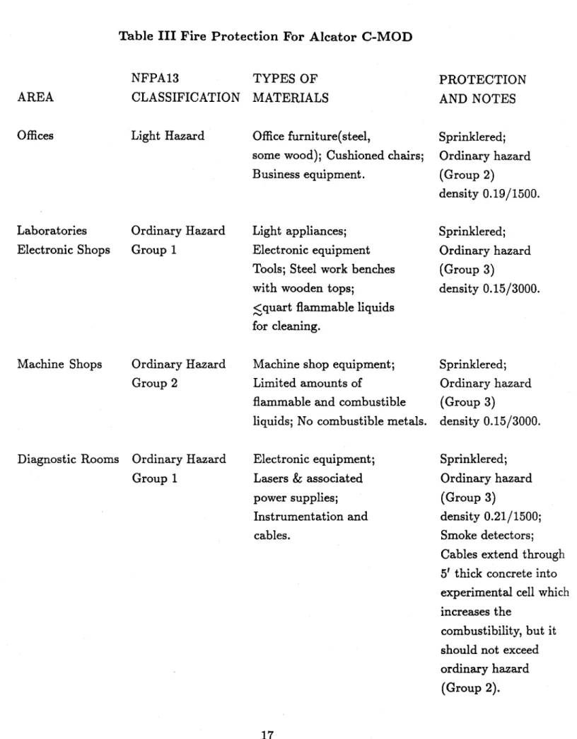
area and the control room, 0.21/1500 (wet pipe) in the diagnostic labs and power room, 0.21/2000 (dry) underneath the floor areas, and 0.19/1500 in the offices shop areas. Table III. provides a summary of the smoke and fire detection systems.
The sprinkler system is required to have a minimum coverage of 0.16/1500 (the mate-rials in these areas are expected to be of the ordinary hazard (group 1) type.) The heads located in the power room, control room, shop areas, rough lab areas and underneath the wooden floors are rated for 165* while those in the diagnostic labs have 212* heads.
The water source is Cambridge city water. A measurement taken at a hydrant at
190 Albany St., May 12, 1982 demonstrated water values of 52 psi static, 48 psi residual
and 1072 gpm. This was the basis for the hydraulic calculations for the sprinkler system installation.
Smoke detectors which are connected to the M.I.T. Proprietary Fire Alarm System are located in the diagnostic laboratories, the experimental cell, and the power room. Smoke detectors which alert Alcator personnel prior to notifying the Cambridge Fire Department are also located inside several power supply cabinets as needed.
Fire extinguishers will be provided and located as directed by the MIT Safety Office. 4.B. Alternator
The alternator building is protected by a preaction sprinkler system that has been extensively reviewed and approved by both the MIT Physical Plant and representatives of
Table III Fire Protection For Alcator C-MOD NFPA13 CLASSIFICATION Light Hazard Laboratories Electronic Shops Machine Shops Ordinary Hazard Group 1 Ordinary Hazard Group 2
Diagnostic Rooms Ordinary Hazard Group 1
TYPES OF MATERIALS
Office furniture(steel,
some wood); Cushioned chairs; Business equipment.
Light appliances; Electronic equipment Tools; Steel work benches with wooden tops;
<quart flammable liquids for cleaning.
Machine shop equipment; Limited amounts of
flammable and combustible liquids; No combustible metals.
Electronic equipment; Lasers & associated power supplies; Instrumentation and cables. AREA Offices PROTECTION AND NOTES Sprinklered; Ordinary hazard (Group 2) density 0.19/1500. Sprinklered; Ordinary hazard (Group 3) density 0.15/3000. Sprinklered; Ordinary hazard (Group 3) density 0.15/3000. Sprinklered; Ordinary hazard (Group 3) density 0.21/1500; Smoke detectors; Cables extend through
5' thick concrete into
experimental cell which increases the
combustibility, but it should not exceed ordinary hazard
Table III-cont Fire Protection for Alcator C-MOD NFPA13 AREA CLASSIFICATION Control Room Experimental Cell RF and Power Room Light Hazard Ordinary Hazard (Group 2) Ordinary Hazard (Group 2) TYPES OF MATERIALS Computer terminals; Tables, desks(usually metal, some wood); Cushioned chairs. Alcator C-MOD (non-combustible, currently 60 tons stainless steel); Diagnostic equipment (final configuration unknown); Combustible materials are prohibited as far as possible.
High voltage and power equipment for Alcator C-MOD and the RF transmitters. Under Wooden Floors PROTECTION AND NOTES Sprinklered; Ordinary hazard (Group 3) density 0.21/1500.
This room has
5' thick concrete
walls, 4' thick roof, 50'x50'x36' high;Smoke detectors; Protection for component systems added as needed. Sprinklered; Ordinary Hazard (Group 3) density 0.21/1500; Smoke detectors All equipment is housed in metal cabinets. Sprinklered(dry); density 0.21/2000.
the insurance underwriters for MIT. Alcator maintains an independent smoke and fire de-tection system that is monitored 24 hours a day by MIT Physical Plant personnel. Alarms during working hours are verified by Alcator personnel before calling the fire department. After working hours Physical Plant calls the Fire Department immediately. The Cambridge Fire Department has reviewed the system and is notified of any changes. Annunciators and maps showing the location of each sensor are placed in conspicuous locations at the entrance to the building.
4.C. Inspection Schedule
The sprinkler systems are tested quarterly. The sprinkler systems and fire extinguish-ers are serviced once a year. The smoke detectors must be inspected semi-annually. The MIT Safety Office will inspect the site quarterly for flammable loading.
The Plasma Fusion Center Safety Committee inspects all facilities twice a year. The site is inspected by DOE at their discretion (usually once a year.)
The Cambridge building inspector and electrical inspector in conjunction with the MIT Safety Office inspect the site once a year.
The Cambridge fire department will receive a tour of the facilities included in the directly connected smoke detector system prior to initial operation. They also inspect the facilities at the discretion of the Fire Chief.
V. Chemical Hazards
5.A. Hazardous Materials
The most frequently used hazardous materials present in the Alcator C-Mod facility are flammable gases, liquefied gases, solvents, lubricating oils, pump oils, and corrosive agents. Occasional handling of Lithium metal and Beryllium metal may be necessary. Activated material handling will be discussed in Sec. 9.D.
5.B. Handling, Storage and Disposal
Flammable gases (such as hydrogen, deuterium, and oxygen) are contained in pres-surized gas cylinders which are secured against falling. Oxygen is stored separately from other flammable gases. The quantity contained on site is kept at a minimum (< 10 bottles) and storage will be in well ventilated areas to minimize the likelihood of explosive releases. An outdoor bottle storage area is provided. The feed system piping to the experiment is checked for leaks prior to operation by pumping out the lines with a vacuum pump.
Cryogenic gases used are liquid nitrogen and liquid helium. The liquid nitrogen will be stored in a large dewar located outside the experimental cell building. Transfer lines will be insulated to prevent skin damage from contact. Liquid helium is obtained in small quantities as needed. Protective equipment is provided as needed.
Solvents such as chlorethane, alcohol, and freon are used primarily in the vacuum shop where ventilation hoods and safety cans are used to limit air concentrations. Gloves, face shields and aprons are provided to prevent skin contact with these solvents. Used quantities are stored and disposed of in 5 gallon lots through MIT disposal procedures.
Lubricating and pump oils are stored and disposed of according to MIT procedures. Pump oil used on the Alcator C-Mod experiment must be collected, analyzed for tritium content, and possibly disposed as radioactive waste, as supervised by the Radiation Pro-tection Office.
Hazardous metals and other materials are stored and handled according to MIT policy, and as recommended by manufacturer supplied Material Safety Data Sheets (MSDS's).
5.C. Right to Know Law
The OSHA Hazards Communication Standard requires that workers be made aware of hazardous materials with which they may come into contact and be instructed in proper handling procedures for those materials. Although MIT qualifies under the Research Lab-oratory Exemption from certain requirements of the act, Institute policies and procedures are designed to comply with the essence of the law. MIT maintains a file of MSDS's on all hazardous materials known to be in use at the Institute, requires inventories from each department of such materials, provides MSDS's to any personnel requesting them, and requires personnel exposed to hazardous material to be instructed in proper handling of
these substances.
The Alcator C-Mod program operates in compliance with the MIT procedures. MSDS sheets are maintained on all hazardous substances and these are provided to employees or students who have reason to work with or to come into contact with these materials.
VI. Air Quality
6.A. Exhaust System
The experimental cell exhaust system is designed to cycle the air in the experimental cell once every hour. The 1500 CFM exhaust fan will be interlocked with the experimental sequence so that a pulse cannot be initiated unless the air is circulating, in order to insure that activated products present in the cell air are not accumulating. The intake and exhaust from the cell is designed so that the cell is at a slightly negative pressure relative to the surrounding areas. The exhaust ductwork is designed so that 2/3 of the flow comes from the floor area of the cell, and the remaining 1/3 from the ceiling.
Three of the four diagnostic laboratories adjacent to the cell are equipped with 1600 CFM fan coil units for heat and air conditioning. The air intake for these is from the roof area adjacent to the labs. The experimental cell air intake is in these labs, and the cell is kept at a slightly negative pressure so that the laboratory air will flow into the cell. The 4th laboratory, the data acquisition room, has a 2400 CFM fan coil unit, also with an intake on the adjacent roof. There is no vent connection with the test cell, however.
6.B. Monitoring
The use of large quantities of liquid nitrogen in the Alcator C-Mod experiment could cause a depletion of oxygen in the experimental cell should a problem develop with the exhaust system or a major leak occur. Thus, oxygen levels in the cell will be monitored and an alarm will be sounded if levels fall below a safe amount, which varies from 16% to 19.5% depending on atmospheric conditions and altitude [9].
VII. Electrical Safety
All Alcator C-Mod electrical systems must meet requirements of the Massachusetts
and the National electrical codes. Alcator employs at least one licensed electrician who ensures that these standards are met. All facilities are routinely inspected for compliance
by the Plasma Fusion Center safety committee. Interlock and safety systems are tested on
a monthly basis following an established procedure.
7.A. Hazards
The high power and high voltages routinely used in the Alcator C-Mod experiment pose a danger of electrocution to personnel working with certain equipment. Most of the high power equipment is located in the power room adjacent to the experimental cell, where access can be routinely controlled.
Individual diagnostic experiments may require the use of high voltage or high energy equipment, such as the capacitor banks used for many laser experiments. Users of such equipment will be expected to provide the required interlocks and other safety features which will be subject to routine inspection by the PFC safety committee.
7.B. Interlocks and Procedures 7.B.1 The Power Room
The Alcator C-Mod power systems will operate with a Kirk safety interlock system (see Appendix B). Such a system was successfully used on the earlier Alcator experiments. This system is designed to protect the power systems as well as personnel.
The entire power room and RF areas will be interlocked so that no power system can be initiated, the alternator can not ramp up, and the control sequence will not be able to start until the system has been properly set. Audio and visual signals will indicate violation of the interlocked system along with the location of the violation. Communication is provided between all parts of the interlocked system, so that violation of any subsystem will effect a controlled shut down of the power systems. If a violation occurs during a pulse sequence, the system will shut down and all breakers will open immediately in a controlled
manner.
The power room is monitored by closed circuit television during operation. Procedures for entry to the power room as well as for clearing the power room of personnel prior to setting the interlock system will be initiated. These procedures will be in place prior to initial power room operation.
The interlock and safety systems are tested monthly, and the results are recorded.
7.B.2 The Alternator
The alternator is throughly protected by a redundant interlock control and monitor-ing system. Critical temperatures, pressures, air, water, and oil flows are continuously monitored. Any problem is annunciated to both the alternator operating crew and to the
C-Mod control room. The action taken depends upon the exact nature of the problem, but is always automatic and requires no human intervention to keep the system in a safe
state. Many faults will disable the drive system and prevent excitation of the machine. The large rotating mass of the alternator requires over an hour to slow to a stop after the drive is removed. During this time it is imperative that cooled lubricating oil be continuously supplied to the bearings. The current system relies on a large station battery to run a DC oil pump and Cambridge city water as an emergency cooling source should there be an area-wide blackout while the machine is rotating. (There are also 2 independent
AC feeds from Cambridge Electric Light Company; in over 7 years of operation both feeds
have never failed simultaneously.) The addition of the flywheel will substantially increase the run-down time, and the station battery has insufficient capacity to maintain the require emergency power. MIT has installed a 250 KW diesel motor-alternator as an emergency power source. The alternator will use the station battery to provide power to essential
systems during the few seconds required for the diesel to come on-line.
VIII. Electromagnetic Radiation
8.A. Lasers
A number of diagnostic experiments on Alcator C-Mod will utilize lasers of sufficient power to cause serious burns or eye damage to personnel exposed to the beams and to scattered light from the beams. Several of these lasers require high voltage and high energy capacitor banks for operation, which poses an additional electrocution risk to personnel.
The diagnostics which require the use of lasers are summarized in Table IV with the type of laser used, the expected hazard to personnel, and the precautions which will be taken to prevent injury. In most cases, an enclosed beam path will prevent access to the laser light. Interlocked power supplies will prevent exposure to high voltages. Access to the diagnostic laboratories will be limited to authorized personnel, and will be controlled
during plasma pulses. Warning lights will indicate when these lasers are operating.
All laser installations will be registered with and inspected by the MIT Radiation Protection Office.
8.B. RF Systems
8.B.1 ICRF
The main safety concerns are RF burns from direct contact with exposed RF voltage on ungrounded conductors and electromagnetic radiation above safe levels in areas where personnel have access. Hazards to personnel from high power operation are controlled by evacuating and locking the experimental cell and power room during plasma pulses. During normal operation there is no exposed RF because everything is enclosed in grounded conductor. The transmitters will not run when there are high reflections so gross errors such as running the RF into an open-ended transmission line will cause immediate transmitter shutdown. Also high power cannot be transferred through the coaxial line unless it is pressurized and the antenna cannot support the voltages associated with high power when the experiment is not under vacuum. Nevertheless the RF will be interlocked such that it cannot be operated into an antenna when the experiment is at air nor when there is a
-~ -~ 4) 4)-o -~ -4 -a t 1 a e ~l - o g o . 4d.9 UT W
0
.. 0 0 U) U U) '.4 0 0 4-a ~~ -a "a S.0 6.I
0 o .4 w 0 0 0 C4 4 -4 U C12 0-Cq
0 :3. -60) .60a U2 '03l0.
4 0 *e00
A A *-'' .- 'vv
0,0 -o 0 0 o -o2a
U2 3. '-0 0 0 0 0 Q -o 't 4) -4. E-4 '-4I,
4.) :3-0 0 4z
4.) 0 hO p-40 0discontinuity in the ground of the transmission system indicating that something is not attached properly.
The principal concern will be during times between experimental runs when testing or conditioning of RF equipment might occur in the cell when other personnel are present. The goal of this analysis is to determine where the main dangers lie and whether personnel can safely work in the vicinity of the RF systems during testing. There is no real danger of direct contact with RF voltages. The main sources of RF radiation are the DC break in the transmission line between the experiment and the transmitters, leakage of RF excited
by the antenna in the vacuum chamber out of windows in ports, and poorly connected
joints in the transmission system that allow RF leaks. The safe level of RF radiation is 1
mW/cm2 (ANSI C95.1.1982 Standard) in the range of 30-300 MHz. This level assumes a 6
minute average. (The Commonwealth of Massachusetts under CMR 122.010 requires that exposure of the general public to RF radiation at this frequency be limited to 0.2 mW/cm2 per half hour.) The Alcator C-Mod system produces up to 1 second long pulses with a
0.1% duty cycle, so the average power is in fact 2 kW for 2 MW pulsing. The following
analysis uses the peak rather than average power.
During testing in vacuum the voltage limit on the antenna will not allow full power operation. A load resistance in vacuum of 0.1 0 is assumed. This is 1/10 of the anticipated lowest plasma load which can be driven at full power. Since the antenna voltage, and therefore current, is fixed by the standoff limit, this means that only 1/10 the power or 200 kW per antenna can be used during testing in vacuum. (The Oak Ridge TFTR antenna ran on a test stand at 70 kV and 170 kW, but it has two current loops, each of which is longer than the C-Mod antenna.) Thus this analysis uses a conservatively high power level. The first suggested source of RF in the cell, the DC break will be designed to keep RF levels below the safe limit. The two other sources of RF in the cell will be analyzed in more detail.
When RF at 80 Mhz is excited in the vacuum chamber, the chamber itself is too small to allow propagation. However the vertical height of the chamber is not that much less than a half wavelength at 80 MHz (1.75 m) so significant RF levels might exist at
adjacent ports. The succeeding analysis assumes that 200 kW goes into an antenna and exits entirely through the adjacent horizontal port. In fact most of the power will be dissipated by the antenna itself and that which does get around the vacuum chamber will not go out only one port. The ports have long extensions which act as waveguide below cutoff, attenuating the RF.
For the lowest order rectangular waveguide mode, TEO,, the attenuation constant for the RF field level is
a = (2 _-W2, ,
where b is larger waveguide dimension. The power attenuation in db can be written as
yout
db = 20log1o( = -20 a L logioe
where L is the length of the waveguide. The vacuum chamber height is 1.2 m and would attenuate the power by about 7 db between horizontal ports. The horizontal ports are
63 cm high and 73.5 cm long, attenuating the power by 30 db. This drops 200 kW to 40
W. The port opening is 1188 cm2 so there would be 34 mW/cm2 in the port opening if it
was completely transparent to RF. This is a high estimate for two reasons. The antenna orientation in the vacuum chamber does not couple effectively to the TEO, mode, the antenna current is vertical instead of radial. Also any port window would cover only part of the opening, further attenuating the RF. Assuming that the port radiates isotropically, the RF level will be down to 1 mW/cm2 at a distance r such that 47rr2 x 1 mW/cm2 equals
the power out of the opening. The RF level would be safe 56 cm away. Even assuming the port radiates with some gain, say 3-6 db, several meters from a port opening would be safe during testing. Direct access to the Alcator C-Mod experiment will be controlled during testing, but it is not necessary to prohibit other activities in the cell. The top and bottom ports, which are much smaller and longer, will be much safer from RF leakage.
Another source of RF levels in the cell would be a poorly attached joint in the RF system. (Procedures for routine testing of joint connections will be instituted prior to initial RF operation.) It is assumed that the flanges between two lengths of coaxial line are not tightened, leaving a 1 mm gap. The surface area of the flanges is roughly 300 cm2,
giving a capacitive impedance of 0.13 f . For 50 fl line this would divide the voltage and power by 1
/
385 and 520 W of 200 kW might leak out. This corresponds to 52 W/cm2 at the outside edge of the flange. Assuming isotropic radiation, the level would be safe 2 m from the leak. Access to within 2 m of the coaxial lines will be controlled during testing and conditioning of the ICRF system.This calculation assumed a matched coaxial line. This is not true in the matching section where voltages can easily be as much as ten times higher when running into a vacuum load. This would increase the safe distance by a factor of three. However the calculation is an overestimate of the power leakage. It assumes a very large gap and uses the reactive impedance of the gap to compute the leakage power. The resistive losses should be much smaller. Access to the area around the RF matching circuits and transmission lines will be controlled during testing. RF monitors (pick up loops) will be set up along
the perimeter to make sure safe levels are maintained.
To ensure safety, extensive RF surveys will be done during the initial operation and periodically thereafter, in order to ensure that exposure levels are not exceeded. Monitors will be positioned near areas where RF levels might be the highest.
It will be necessary for RF personnel to approach the RF equipment during testing. They will have monitors equipped with meters to measure RF levels. The equipment will be surveyed for leaks periodically to insure personnel safety as well as to limit induce noise levels for other diagnostics.
8.B.2 Lower Hybrid and ECH
It is possible that lower hybrid current drive experiments will be conducted on Alcator C-Mod using the 4 MW 4.6 Ghz system which was used on Alcator C. The exposure limits at this frequency are 5 mW/cm2 for 0.1 hour (ANSI c95.1-1982) and 1 mW/cm2 for 0.5
hour (CMR 122.010). ECH experiments in the 240-280 Ghz range are also anticipated. The shorter wavelengths of these systems increase the likely level of RF leakage from the Alcator C-Mod windows over what is expected from the ICRF system. Therefore, access to the cell and to the sources will be controlled during testing, conditioning, and high
power operation of these systems.
8.C. Magnetic Fields
Plasma confinement and shaping on Alcator C-Mod is obtained by using high magnetic fields. The toroidal field (9T at the plasma center) is confined to the region inside the magnetic field windings. The poloidal fields, however, extend well beyond the tokamak structure. The expected field contours are shown in Fig. 6. For the highest current operation, a magnetic field of 5 Gauss lasting 1 s could be reached at the unrestricted site boundaries to the southeast of the experimental cell. This level is 50% of the 10 Gauss limit used as a guideline for excluding people wearing pacemakers at LLNL [1]. The field levels at all other unrestricted boundaries are well below this value. Thus it is not expected that magnetic fields generated during the Alcator C-Mod experiment will pose health hazards to MIT personnel or to the general public.
I A I ... 4 5 4 5 * S - . . S * * .** *S S * * .*. 4 S a -* a a .* * * 4S a * 4 * 4.-* 5 S ~ ~ * *F~S~S St 5 444 44 * ~ 5..* * n - S I * 5 4 4 **.. a 5 4 4 - a * * *.~.. I * S 5 1 5 * S * ** a S S - - a * a * a .a.-0 0 U, 00 4 5 0 0
6
II N 0 1~ (Nz
(5~ C', *0 L 0 0 0 'S.... 0 0 C.,' S.... 00 9.5w 0 Q I.' 0o
'4,o
0'9-I
.4.1 0o
-U,I
0-o
1~ 01 ~ 0 C.,' 4.)I ~9
S S 4 5 S S S S S S S * S S S S S S S S * S S S * S S S * U, S S * S * S * S * S * S * S 0 I', I IIX. Ionizing Radiation 9.A Method of Calculation
9.A.1 Introduction
The Alcator C-Mod experiment is expected to produce neutron rates as high as 5 x 10"
n/sec (1 second pulse) during high performance deuterium operation. This presents a potential hazard to Alcator personnel and to the general public from both direct neutron and -y radiation produced during an Alcator C-Mod pulse as well as from activated isotopes resulting from neutron capture. The radiation shielding developed for Alcator C-Mod is designed to restrict radiation doses to the general public to within the guidelines required for DOE facilities (see Appendix C). In addition, exposure to Alcator personnel is restricted to 1.25 Rem per quarter, as required by 10-CFR-20 [2] and DOE 5480.1 Chg 6 Chapter XI [3].
9.A.2 Neutron Transport Codes
The neutron and y shielding requirements have been assessed using two coupled neu-tron photon transport codes. The ANISN code
[41
numerically solves the one dimensional Boltzman transport equation for neutrons by a discrete ordinates method. ANISN pro-vides a fast calculation of neutron penetration and y production through thick shielding materials, and has a convenient post-processing program for determination of activated isotope concentrations in surrounding materials, but provides only one dimensional infor-mation. The MCNP code [5] tracks neutron and photon transport in three dimensions using a Monte-Carlo technique. Three dimensional analysis is necessary for determina-tion of transport through penetradetermina-tions in the shield walls, but requires a large amount of computer time.The neutron source energy for all of the code calculations is assumed to be distributed with 97% of the neutrons at 2.5 MeV from DD reactions and 3% of the neutrons at 14 MeV from DT reactions.
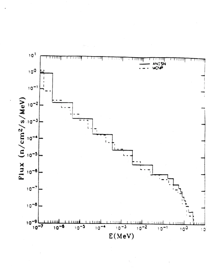
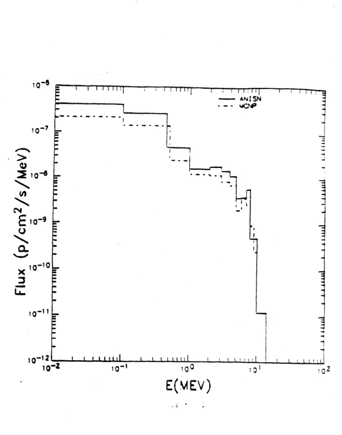
obtain the neutron and y flux which penetrates the shield wall through the solid concrete structures. The results of this model were compared to a 1985 MCNP study [6] prepared for the Alcator C-Mod proposal. The neutron and y fluxes incident to the inner shield wall obtained from the two codes are compared in Figs. 7a and 7b. The agreement is very good, although the total - flux found by the ANISN code is twice that found by
MCNP. Similarly, the total neutron flux outside of the 5' concrete shield wall was found by the MCNP calculation to be 5x10-13 n/cm 2/source neutron and 4.5x10- 13 n/cm2/source
neutron by the ANISN code. The ANISN calculated y flux was 1.3x 10- 17/cm2/source
neutron outside of the concrete cell wall, a factor of 2 higher than that found using MCNP. For analysis of the penetrations in the Alcator C-Mod shield wall, ANISN was used to generate the flux energy distribution of neutrons incident to the shield wall. This distribution was used as the basis for a surface source for an MCNP calculation of the transport through the wall penetrations.
Calculation of the activity of isotopes present in the ground water, the concrete shield, and the air in the cell was done using ANISN generated neutron flux profiles and applying an activity post processing program, AAP [7]. The machine structure activities were adapted from those published in [6] using a lower neutron rate and a lower pulse repetition rate to reflect the updated machine design performance criteria.
Dose rate calculations are done by integrating the energy dependent neutron and Y flux values at the point where the calculation was made with the energy dependent dose conversion factors listed in Table Va and Table Vb. The accumulated yearly dose assumes that each pulse in the year produces 5 x 10" n/sec (1 second pulse), and that 3750 pulses
(25 pulses per day, 5 days per week, 30 weeks per year) are taken per year. This assumption
will produce an overestimate of actual dose rates, because it is highly unlikely that every pulse will achieve the highest level of performance, and it also assumes that all operation will be in deuterium while some hydrogen operation is anticipated.
The calculated activated isotope levels also assume that 3750 high performance pulses are produced per year.
- ANISN I ~-- - 'MCN~P 100 -CN -2 10 -> 10 -10-9 I
ii
il
I I I I I i iiih I m iI 10-7 10-6 10-5 10- 10~3 10-2 1-1 10 11E(MeV)
Figure 7a. Comparison of neutron flux as a function of energy at the Alcator CMOD biological shield wall calculated by ANISN (solid line) and MCNP (dashed line).
vvrvq-r-r-m~iT-T -r---.T ; I i - ANIS
..
c~
a a a ma ilti I I I NF
F---T-r
1
1 I 100E(MEV
)
Figure 7b. Comparison of -y flux as a function of energy at the Alcator CMOD biological
10-6
E
1()-9
Q X 10-10 i-11~i 12 -10-2 .. . i i L i I I I L 10-1Table V.a Neutron Fluence to Dose Rate Conversion Factor* Neutron Energy (MeV) rem/(n/cm2)
2.5 x 10⁻⁸ 1.02 x 10⁻⁹ 1.0 x 10~7 1.02 x 10⁻⁹ 1.0 x 10⁻⁶ 1.24 x 10⁻⁹ 1.0 x 10⁻¹ 1.26 x 10⁻⁹ 1.0 x 10⁻⁴ 1.16 x 10⁻⁹ 1.0 x 10⁻³ 1.04 x 10⁻⁹ 1.0 x 10⁻² 9.89 x 10⁻¹⁰ 1.0 x 10~1 6.03 x 10~9 5.0 x 10~1 2.57 x 10⁻⁸ 1.0 3.67 x 10⁻⁸ 2.5 3.47 x 10⁻⁸ 5.0 4.33 x 10⁻⁸ 7.0 4.08 x 10⁻⁸ 10.0 4.08 x 10⁻⁸ 14.0 5.78 x 10⁻⁸
Table V.b -y Fluence to Dose Rate Conversion Factors* y Energy (MeV) 0.01 0.015 0.02 0.03 0.04 0.05 0.06 0.08 0.1 0.15 0.2 0.3 0.4 0.5 0.6 0.8 1.0 1.5 2.0 3.0 4.0 5.0 6.0 8.0 10.0
*Determined from ICRP-21
rem/(//cm2) 7.72 x 10⁻¹⁰ 3.22 x 10⁻¹⁰ 1.63 x 10⁻¹⁰ 7.11 x 10⁻¹¹ 4.33 x 10⁻¹¹ 3.33 x 10⁻¹¹ 3.08 x 10⁻¹¹ 3.33 x 10⁻¹¹ 4.08 x 10⁻¹¹ 6.61 x 10-" 9.58 x 10⁻¹¹ 1.54 x 10⁻¹⁰ 2.14 x 10⁻¹⁰ 2.53 x 10⁻¹⁰ 3.17 x 10⁻¹⁰ 4.08 x 10⁻¹⁰ 4.97 x 10⁻¹⁰ 6.78 x 10⁻¹⁰ 8.42 x 10⁻¹⁰ 1.11 x 10⁻⁹ 1.32 x 10⁻¹ 1.54 x 10⁻¹ 1.74 x 10⁻⁹ 2.14 x 10-2.53 x 10-9
9.B Direct Radiation
9.B.1 The Biological Shield
The experimental test cell is constructed with 5' thick concrete walls with a 40" concrete floor and a 48" concrete ceiling in order to attenuate the neutron and -y radiation. The cell layout provided (Fig. 4) shows the boundary areas for unrestricted access by members of the general public. The unrestricted areas are 15' from the cell south wall,
8-15' from the east wall, 22' from the west wall, and 128' from the north wall.
The penetrations through the shield wall are shown in Fig. 8 and Fig. 9. The north wall has an 10' x 4' door leading into a vestibule constructed of 3' concrete walls. A 4' x 4' penetration is directly above the door, also leading into the vestibule, for the power buswork, RF transmission lines, and machine cooling to enter the experimental cell. The power and cooling systems exit the vestibule area through a 4' x 6' hole in the ceiling.
A 14' x 13' opening adjacent to the vestibule designed to allow large equipment to be
moved into the experimental cell is sealed with a 5' thick concrete door during operation in order to preserve the integrity of the shield wall in that area.
The east wall is penetrated by an 8' x 4' emergency exit located at the southernmost corner of the shield wall. The emergency exit leads into a vestibule area which is con-structed of 5' thick concrete along the south wall, and 3' thick concrete as its eastern wall. The exit from this vestibule is at grade, 6.5' above the experimental cell floor. The ceiling is 3' concrete.
There are four types of smaller penetrations as shown in Fig. 9. Electricity and fiber optics cables enter the experimental cell through a series of 5" diameter sweep pipes which penetrate the shield wall horizontally then bend through 90* and exit in the floor. There are 6 of these adjacent to the vestibule in the north wall and 25 entering the laboratory area through the west wall. The area surrounding the bend in the pipes is filled with gravel extending a distance of 11' or greater from the bend. The sweep pipes entering the laboratory areas are clustered in such a manner that 19 exit in the data acquisition area
4 -J U U 4 4 a. --- J Lii ~LJ 2 Ud W< W-.~ -~w.
w w
u 1) w >I
CA o0 0 1 4a 06 UShield Wall Penetrations
5@
5"
Sweep Pipe
Figure 9. Minor penetrations in the Alcator
CMOD
biological shield wall.8" x 14" Duct
2.5" Pipe
0.12" Straight Pipe
The next type of penetration is for the air intake into the cell and consists of four 8" x 8" duct which were designed to undergo two 450 bends in the shield wall. The entrance and exit are displaced 2' vertically. These are located in the west wall, one exiting in each of the laboratory rooms. These were not installed to the specified design, and the final configuration involves reduction of the vertical dimension by installing 2" Masonite blocks in the entrance and exit holes. The neutron leakage of this configuration will be tested with a neutron source, and shadow shielding will be installed if needed.
The fifth duct for exhausting the cell air exits through the east wall into the emergency exit vestibule. This 12" x 14" duct was also installed incorrectly. Reducing the neutron transport through this duct involved removing much of the concrete and completely recon-figuring the vent. The neutron leakage through this vent will also be tested, and shadow shielding will be installed if necessary.
The cooling water for the air conditioner enters the experimental cell through three
2.5" diameter pipes which undergo two 45* bends in the shield wall, with entrance and exit pipes displaced 2'. These all penetrate the West wall into the southernmost laboratory room.
Finally diagnostic access into the laboratory areas can be provided through a number of straight through pipes. Twenty-one 12" diameter pipes have been cast through the concrete shield wall, but will be plugged with water extended polyester (WEP) plugs when not in use. Shadow shielding is required for any experiment utilizing straight through access to the experimental cell of sufficient quantity to lower radiation levels outside the laboratory area to less than the levels recommended by DOE for the unrestricted boundary. Access to the laboratory areas is controlled during experimental operation.
There are no penetrations through the south shield wall. 9.B.2 Dose Rates
The combined neutron and -y radiation dose at the inside wall of the biological shield was found from the ANISN calculation to be 21 Rem from a 5 x 10¹⁵ n/sec pulse of 1 second duration. This requires that personnel be excluded from the experimental cell
during operation.
The neutron and -Y flux penetrating the unbroken concrete shield wall at the shortest distance between the experiment and the wall are plotted as a function of energy in Fig. 10a. and 10b. Using the assumptions of 9.A.2 (3750 high performance pulses per year),the expected neutron and y dose rates per pulse at the outside of the concrete are 1.73x 10⁻⁶ Rem and 2.53x 10' Rem respectively. This is equivalent to 8.44x 10⁻² mRem/hour during an 8 hour (25 pulse) day. At the fence along the southern perimeter of the site, the maximum yearly dose rate for this type of continuous full performance operation would be
37 mRem. Although it is clear from Table VI that the dose rate at the eastern perimeter
could be as high as 58 mRem in any given year, this area is between two MIT buildings and access can be controlled if continual high performance operation is achieved. Steps will be taken (as described in Appendix C) to ensure that the site boundary dose is kept well below this value. The concrete shield wall provides sufficient attenuation of the neutrons and y rays for typical operation.
Dose rates calculated at different site boundaries outside the shield wall produced
by MCNP analysis of the penetrations are detailed in Table VI. Limitation of the dose
rates to the design values due to the two large penetrations (the entrance vestibule and the emergency exit) requires the installation of several large Benelex or Masonite doors in those locations. Sliding doors will be installed over those openings inside the biological shield and swinging shield doors may be installed at the exits if required by the operation of the experiment. Site boundary dose rates from the electrical sweep penetrations and water lines are quite low. Shadow shielding will be required surrounding any open diagnostic port, and may also be required for some of the air intake vents.
Table VII details expected dose rates from direct radiation in areas accessible by Alcator C-Mod personnel.
9.C Activation Hazards 9.C.1 Ground Water
108 -10-10 _
E
10~1-C/) Z10-12 -10-15 10-17-10-18 I | I I I I I 10-7 1 -6 10-5 10-4 10-3 10-2 10-1 100 101 102E(MEV)
10-11 I I ~I 1 11111II 111
101 1C0
L
101 102
E(MEV)
Figure 10.b ANISN calculation of the -y CMOD biological shield.
flux as a function of energy outside the Alcator I I I 1 I l1ii
z
C/)
0
-3E
10-14 10-2 10-11 I I I 1 11111 L-L-LLw -4a 0 0 4.1 I-0 0 -. 0 x U* vz u6 ui - 1- - -x -x-x -x - 0 i to I I 1 r, - - 1.q -4 xxx x m~ 0 C4 'I o C 42) -S A a 0 0 ~0 0 -4.3 0 4.) ~0 0 ~.4 -S >. 4. Cl 0 x to 0 I 10 -4 0 x .2 U 0 r-4 x 0 '-4 x C4 r-.4 o6
C4 00 x-4 o o x 1x X X -400 LO r-4 .-0 .4 Sx x x x o6 o 1i I Is 0 0 0 X X X 00 00 N Cei 6 I ONI 0 0i-n 0000 x 0 -0 '.4 00 0 S -q -4 x x x 0'!00 - 16 r-00 3 OOs U)o U x X 0 U) 0 0 V V '.5 U) V 0 *