Publisher’s version / Version de l'éditeur:
Vous avez des questions? Nous pouvons vous aider. Pour communiquer directement avec un auteur, consultez la première page de la revue dans laquelle son article a été publié afin de trouver ses coordonnées. Si vous n’arrivez pas à les repérer, communiquez avec nous à [email protected].
Questions? Contact the NRC Publications Archive team at
[email protected]. If you wish to email the authors directly, please see the first page of the publication for their contact information.
https://publications-cnrc.canada.ca/fra/droits
L’accès à ce site Web et l’utilisation de son contenu sont assujettis aux conditions présentées dans le site LISEZ CES CONDITIONS ATTENTIVEMENT AVANT D’UTILISER CE SITE WEB.
Journal of Thermal Insulation, 11, pp. 263-269, 1988-04
READ THESE TERMS AND CONDITIONS CAREFULLY BEFORE USING THIS WEBSITE. https://nrc-publications.canada.ca/eng/copyright
NRC Publications Archive Record / Notice des Archives des publications du CNRC :
https://nrc-publications.canada.ca/eng/view/object/?id=86be7879-2664-4dad-aa19-3c3a5121e5e1 https://publications-cnrc.canada.ca/fra/voir/objet/?id=86be7879-2664-4dad-aa19-3c3a5121e5e1
NRC Publications Archive
Archives des publications du CNRC
This publication could be one of several versions: author’s original, accepted manuscript or the publisher’s version. / La version de cette publication peut être l’une des suivantes : la version prépublication de l’auteur, la version acceptée du manuscrit ou la version de l’éditeur.
Access and use of this website and the material on it are subject to the Terms and Conditions set forth at
Heat transport through fibrous insulation materials
S e r
TH1
-Nationai Research Comreil national Council Clnada
de
mchedws
Canadano.
1566
c. 2 Institute for lnstitut de
BLDG Research in recherche en
Construction construction
Heat
Transport Through
Fibrous Insulation Materials
by M.K. Kumaran and D.G. StephensonReprinted from
Journal of Thermal Insulation Vol. 11, A ril 1988
p. 263-26 !C
(IRC Paper No. 1566)
NRCC 29639 NRC
J R C
-
C l S nI
L I B R A R Y
N O I
2s
me
I
B I B L I O T H ~ Q U E
I R C
CNRC-
#CIS7On montre que le flux de chaleur B travers les mat6riaw isolants fibreux peut Etre repr&entk par un ensemble de trois constantes matdrielles dans une large gamme de tempt5ratures d ' i n w t pratique. Ces constantes peuvent &re ddterminh B l'aide de mesures standard faites au moyen de l'appareil B plaque chaude gardk.
Heat Transport through Fibrous
Insulation Materials
M. K. KUMARAN
ANDD.
G . STEPHENSON Institutefor Research in ConstructionNational Research Council Canada
Ottawa, Ontario K I A O R 6
ABSTRACT
It is s h o w n that heat flux through fibrous insulation materials can b e represented by a set o f three material constants over a widc range o f tcmpcrature o f practical in- terest. These constants can bc dctcrmincd from standard guardcd-hot-platc appara- tus mcasurcmcnts.
KEY WORDS Fibrous insulation. hcat flux.
INTRODUCTION
T
HE STANDARD PROCEDURE for measuring the thermal conductivity of thermal insulation is based on Fourier's equation,but recast as
In the above equations, q is the heat flux at a steady state through a speci- men of thickness L, (dTldx) is the temperature gradient at a location in the direction of the heat flux, and X the thermal conductivity at that location. The temperature gradient is approximated in Equation (2) by - (TH - Tc)IL
where TH and Tc are respectively the hot and cold surface temperatures of a specimen. The thermal conductivity so calculated is usually referred to as the apparent thermal conductivity at the mean temperature T, defined as (TH
+
Tc)/2.
Equation (2) gives the right value for when it is either independent of temperature or linearly dependent on TM. The latter condition is often fulfilled for small values of (TH
-
Tc). Unfortunately this constraint meansthat errors in measuring the values of TH, Tc and q have a relatively large ef-
fect on the accuracy of
A.
It would be desirable, therefore, to be able to use larger values of (TH-
Tc) and consequently larger values of q. It would also be beneficial to be able to determine how X varies with temperature. This note presents a way of achieving both of these objectives using the results from standard types of apparatus for measuring X.For fibrous insulating materials, it has been shown recently [ I ] that the heat flux is related to TH and Tc by
Equation (3) may be written in differential form as
Comparison of Equations ( 1 ) and (4) gives, for the above materials,
As practical problems usually involve calculating q, and
X
is just a datum used in the calculation, it is better to utilize the a , b and c constants directly in Equation (3). In fact, the concept of an apparent thermal conductivity that is a function of mean temperature is of limited value when dealing with ma- terials like fibrous insulation for a wide range of temperature.Equation (3) was derived on the basis of the theory of irreversible pro- cesses [ I ] . The constant ( a ) was identified as representing the conductive part of the heat transport, ( c ) as the radiative part and ( 6 ) as an interaction be- tween radiation and conduction. It was implied [ I ] that these constants have the status of a set of material properties, independent of temperature and size. The experimental results reported in this note confirm that this is a valid assumption.
MATERIALS AND METHOD
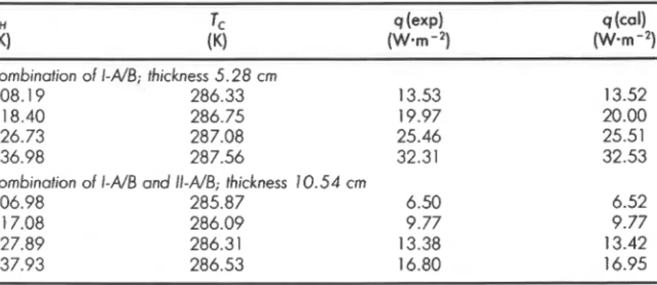
Table I . Heat flux through the combinations of specimen pairs I-AIB and 11-,416
at various sets of hot surface temperature TH and cold surface temperature Tc; q(exp) is the measured heat flux and q(ca1) the heat flux calculated according
to Equation (3).
combinotion of I-AIB; thickness 5.28 cm
308.1 9 286.33 13.53
3 18.40 286.75 19.97
326.73 287.08 25.46
336.98 287.56 32.31
combinotion of I-AD and 11-A&; thickness 10.54 cm
306.98 285.87 6.50
3 1 7.08 286.09 9.77
327.89 286.3 1 13.38
337.93 286.53 16.80
Table 2. Heat flux through the specimen pair Ill-AIB at various sets of hot surface temperature TH and cold surface temperature Tc; q(exp) is the measured heat
flux and q(ca1) is the heat flux calculated according to Equation (3). T"
I::I
q (expl 9 (call(K) (W-rn-') (W-rn-2) (TH - Tc) < 25 K* 304.32 282.09 19.75 19.70 308.00 286.30 19.54 19.59 309.41 287.65 19.84 19.77 322.97 302.39 19.85 19.98 323.24 302.88 19.87 19.80 336.84 31 6.97 20.63 20.62 356.88 337.32 22.45 22.32 370.72 348.07 27.35 27.39
i
(TH - Tc)*
2 5 K 8 * 4 15.64 326.04 1 13.7 115.0I
430.76 326.26 139.4 139.4 445.49 326.24 163.3 165.0 ! 469.95 327.55 209.3 210.0 494.44 326.80 258.1 262.6 51 8.88 327.31 376.5 383.3 566.85 327.55 445.6 450.6i
*Only these measurements were used to estimate the constants a, b and c for Ill-A/B:o = 1.337 x lo-' W-m-'.K-' b = 2.066 x lo-' W.m-'.K-2-6
c = 4.1 12 x W.m-'.K-'
vestigation. These six slabs formed three pairs of test specimens as follows:
1. Specimen pair I-A/B, each 58.4 cm x 58.6 cm and thickness 2.64 cm;
they weighed 461.2 g and 461.3 g respectively when dried.
2. Specimen pair 11-A/B, each 58.4 cm x 58.4 cm and thickness 2.63 cm;
they weighed 482.0 g and 483.0 g respectively when dried.
3. Specimen pair 111-A/B, each 57.9 cm x 57.9 cm and thickness 3.85 cm;
they weighed 626.8 g and 628.1 g respectively when dried.
The pairs I-A/B and 11-A/B were prepared from the same batch of mate- rial, and the specimen pair 111-AIB was prepared from a different batch of material.
The experimental quantity determined was always the steady state heat flux through the slabs for known values of hot and cold surface tempera- tures. The measurements were done either on a guarded hot plate (GHP) ap- paratus [2] or on a heat flow meter (HFM) apparatus 131.
As reported earlier [I], the specimen pair I-A/B was used in ten GHP mea- surements, in different ranges of TH and Tc. Analysis of those results gave,
Subsequently, this pair of specimens was placed one over the other in the
HFM apparatus to form a specimen of total thickness, 5.28 cm and the heat
flux through the combined slab was determined at four pairs of hot and cold surface temperatures.
Yet another specimen of total thickness, 10.54 cm was obtained by placing the specimen pair 11-AIB over the above combined slab and the heat flux through the combination of four slabs was determined at four pairs of hot and cold surface temperatures. The results from the above eight sets of mea-
surements are listed in -Table
1
.
IThe specimen pair 111-A/B was used in several GHP measurements in the J temperature range 282 to 567OK. In an initial set of measurements, in the
temperature range 282 to 371°K, the temperature difference (TH
-
TC) wasalways lower than 25OK. But in a subsequent set of measurements, the tem- perature difference was as high as 239.3OK. The results from these measure- ments are summarized in Table 2.
DISCUSSION
The constants a, b and c evaluated from the earlier measurements [I] and quoted above for the specimen pair I-AIB were used to calculate the heat
Heat Tvansport through Fibrous Insulation Materials 267 fluxes using Equation (3) through the combination of two or four slabs at the different sets of TH and Tc given in Table 1. These calculated values are also listed in Table 1. It can be seen that the agreement between the measured and calculated values is excellent in all the cases. This suggests that the con- stants a, b and c may be treated as true material constants independent of the thickness of the specimen or temperature.
The results in Table 2, at small differences in TH and Tc alone, were used in Equation (3) to evaluate the constants a, b and c for the specimen pair III- AIB. These constants were then used to calculate the heat flux in the whole experimental range of temperature. The values so calculated are also listed in Table 2. The largest deviation between the measured and calculated heat fluxes is 1.8%. A deviation of this magnitude is well within the precision of the experimental technique. This agreement once again confirms that for glass fibre insulation an equation like Equation (3) with three coefficients can represent heat flux through the insulation over a wide range of temperature of practical interest.
The material in specimens I-AIB and 11-AIB differed by about 6% in den- sity, but were made of the same type of glass fibre and binder, and have es- sentially the same values for the characteristic constants a, b and c, as illus- trated in Table 1. Specimens 111-AIB, on the other hand, had nearly the same density, but were made of smaller diameter fibres and possibly had a differ- ent binder as well. Its characteristic constants are different from the other specimens, particularly the b coefficient, which is nearly six times larger than for the other specimens. Probably, the values of these coefficients reflect the fibre size and binder characteristics.
The heat flux under steady-state conditions through a layer of material can be calculated directly using Equation (3), or it can be obtained using Equa- tions (2) and (5). This latter procedure is valid when TH
-
TC is small, butTable 3. Comparison of heat fluxes, q, calculated from two different equations at various hot and cold surface temperatures; the value of X corresponds to the
mean temperature, TM.
TM A q = (XIL)(T,.,
-
1,) q from Equation (3) (K) (Wen-'-K-'1
(W-m-9
(Wmm-?)300 250 275 0.02997 14.98 15.02
350 250 300 0.03300 33.00 33.34
400 250 325 0.03654 54.81 56.08
is not appropriate for large values of TH
-
TC. The error due to using the thermal conductivity for the mean temperature is illustrated by the values in Table 3. This shows that when the temperature drop across a layer of mate-rial is large, Equation (2) underestimates q even though the value of X that is
used is correct for the mean temperature. Equation (3), on the other hand, as
shown above, gives the correct value of q for any values of T H and Tc.
The principal advantage, however, of Equation (3) is that the coefficients
a, b and c, are independent of the temperature. Thus they can be determined
from the results of a series of tests with temperatures in a range that is con- venient for testing, and then used for temperatures that are outside of that range.
Another advantage is that the values of b and c can also be used to calculate the value of dXldT for any temperature. This is required as a datum when solving the differential equation that describes the temperature and heat flux under non-steady-state conditions.
CONCLUSIONS
The ASTM Standard Test Methods C177-85 and C518-85 can give ac- curate values of the thermal conductivity at the mean of the hot and cold plate temperatures, provided the difference between these temperatures is not too large. But this conductivity should only be used when the tempera- ture difference across a layer of material is small. These limitations can be overcome by using Equation (3) with the three coefficients that are proper- ties of the material.
It would be desirable to revise the ASTM Standard Test Methods to give
the a, b and c coefficients rather than just X. When the a, b, c values are known
they can be used to evaluate both X and dXldT for any T.
ACKNOWLEDGEMENTS
The authors gratefully acknowledge the technical assistance of Mr. J. G.
~ h e r i a u l t and Mr. R. G. Marchand. The authors are indebted to Fiberglas
Canada Inc. for permitting them to use a set of data obtained at the Thermal Testing Laboratory, Sarnia, during recent round-robin measurements.
This paper is a contribution from the Institute for Research in Construc- tion, National Research Council Canada.
-.
REFERENCES
1. Kumaran, M. K. and D. G. Stephenson. "Heat Transport Through Thermal In- sulation: An Application of Thermodynamics of Irreversible Processes," ASME Paper No. 86-WAIHT-70, ASME Winter Annual Meeting, pp. 1-4 (1986).
Heat Transport through Fibrous Insulation Materials 269
2. ASTM Standard Test Method C177-85. "Standard Test Method for Steady-State Heat Flux Measurements and Thermal Transmission Properties by Means of the Guarded-Hot-Plate Apparatus," 1986 Annual Book of ASTM Standards, Volume 04.06, pp. 21-36.
3. ASTM Standard Test Method C518-85. "Standard Test Method for Steady-State Heat Flux and Thermal Transmission Properties by Means of the Heat Flow meter Apparatus," 1986 Annual Book of ASTM Standards, Volume 04.06, pp. 197-213.
BIOGRAPHIES M. K. Kumaran
Dr. M. K. Kumaran is an Associate Research Officer at the Institute for Research in Construction, National Research Council of Canada. He received his BSc (Chemistry and Physics) and MSc (Pure Chemistry) degrees from Kerala University, India, in 1965 and 1967 and Ph.D. (Cherni- cal Thermodynamics) degree from University College, London, England, in 1976. He worked as a Lecturer in Chemistry at Sree Narayana College, Can- nanore, India (1967-1980) and as a Research Fellow at Massey University, New Zealand (1980-1981) before he joined the NRCC as a Research Asso- ciate in the Division of Chemistry. He joined the research staff of IRC in 1984.
D. G . Stephenson
Dr. Stephenson received a BASc in Engineering Physics from the Univer- sity of Toronto in 1949, and a Ph.D. in Mechanical Engineering from the University of London in 1954. He joined the staff of the Division of Build- ing Research of the National Research Council of Canada in 1954 and has remained with that organization ever since. He was head of the Building Services Section from 1969 to 1978 and then coordinated the research on en- ergy conservation until that program was eliminated in 1984. He is cur- rently a Principal Research Officer in the Building Services Section and is developing testing procedures for determining the dynamic thermal charac- teristics of walls.
T h i s p a p e r