Publisher’s version / Version de l'éditeur:
Vous avez des questions? Nous pouvons vous aider. Pour communiquer directement avec un auteur, consultez la première page de la revue dans laquelle son article a été publié afin de trouver ses coordonnées. Si vous n’arrivez pas à les repérer, communiquez avec nous à [email protected].
Questions? Contact the NRC Publications Archive team at
[email protected]. If you wish to email the authors directly, please see the first page of the publication for their contact information.
https://publications-cnrc.canada.ca/fra/droits
L’accès à ce site Web et l’utilisation de son contenu sont assujettis aux conditions présentées dans le site
LISEZ CES CONDITIONS ATTENTIVEMENT AVANT D’UTILISER CE SITE WEB.
NECEC 2010: 18th Newfoundland Electrical and Computer Engineering
Conference [Proceedings], 2010-11-04
READ THESE TERMS AND CONDITIONS CAREFULLY BEFORE USING THIS WEBSITE. https://nrc-publications.canada.ca/eng/copyright
NRC Publications Archive Record / Notice des Archives des publications du CNRC :
https://nrc-publications.canada.ca/eng/view/object/?id=49d1ac1f-d9ad-4d56-9dc5-038b436111ea https://publications-cnrc.canada.ca/fra/voir/objet/?id=49d1ac1f-d9ad-4d56-9dc5-038b436111ea
NRC Publications Archive
Archives des publications du CNRC
This publication could be one of several versions: author’s original, accepted manuscript or the publisher’s version. / La version de cette publication peut être l’une des suivantes : la version prépublication de l’auteur, la version acceptée du manuscrit ou la version de l’éditeur.
Access and use of this website and the material on it are subject to the Terms and Conditions set forth at
A Planar Motion Mechanism (PMM) for ocean engineering studies
Millan, David; Thorburn, Paul
A Planar Motion Mechanism (PMM) for
Ocean Engineering Studies
David Millan, P. Eng, Paul Thorburn, P. Eng. , National Research Council Institute for Ocean Technology
Abstract- A PMM is an electromechanical device
used to move a model ship in a pre-programmed series of motions in a test tank facility. The forces and moments on the model and other data relating to performance are measured. The results of these tests are used to predict the full-scale vessel’s performance, enabling designers to create safer and more efficient vessels. At NRC-IOT, surge motion is provided by the carriage movement along the tank, and the sway and yaw motions by the PMM. This paper describes the capabilities of the NRC-IOT PMM, and the control system interface between the carriage and the PMM.
Maneuvering, ship model testing, 1. Introduction
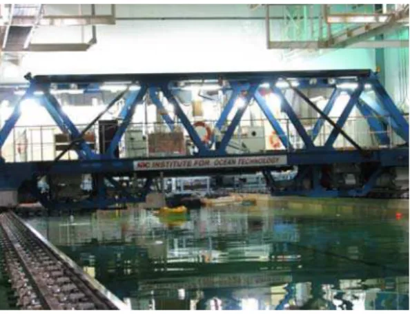
Figure 1: the IOT Ice Tank carriage with the PMM attached to the Test Frame, with the yellow model icebreaker attached to the PMM. Beginning in 1995, NRC-IOT developed a PMM as an in-house pilot project. Since then, IOT and Oceanic Consulting Corporation have used this device extensively. The experience gained was unique and extremely valuable. However, the research carried out with this device under ice conditions revealed major weaknesses in its capability to accurately model performance during manoeuvring in ice. These weaknesses
were due to the lack of rigidity within the current system, resulting in unspecified deflections and vibration when loads were applied, limiting the ability to validate numerical models. In addition to its performance limitations, the pilot PMM had become very difficult to maintain with a dated control system and software. There were also problems with electrical grounding and ineffective shielding of signal lines. After considerable study of the feasibility of refurbishing the old PMM, this option was deemed to be too expensive and time consuming, given the limited number of IOT staff with the necessary mechanical and electronic expertise, and the ongoing operational demands on their time.
For the same reasons, in-house design and fabrication of a new PMM was not a viable option. In late 2007, IOT awarded a contract to Cussons Technology Ltd. of Manchester, England for the design and fabrication of a new PMM, including a six-component force balance and analysis software.
For motion references, refer to Figure 2, a simple representation of a test tank.
Figure 2: test tank showing coordinate system. As shown in Figure 2, the PMM uses a standard right handed coordinate system with the positive z-axis pointing downward (into the paper). Surge (x-axis) is positive in the forward direction of carriage travel. Sway (y-axis) is positive to starboard relative to the forward direction of carriage travel. Yaw (rotation around the z-axis) is positive for rotation to starboard, clockwise
Tow Tank or Ice Tank Y
when looking down on the model with the bow pointing in the forward direction of carriage travel.
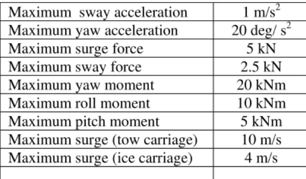
The main specifications of the PMM are listed in Table 1.
Maximum sway acceleration 1 m/s2 Maximum yaw acceleration 20 deg/ s2 Maximum surge force 5 kN Maximum sway force 2.5 kN Maximum yaw moment 20 kNm Maximum roll moment 10 kNm Maximum pitch moment 5 kNm Maximum surge (tow carriage) 10 m/s Maximum surge (ice carriage) 4 m/s Table 1. Note that surge (x-axis motion) is provided by the carriage as determined by a command signal from the PMM.
2. System Description
Figure 3; Block diagram of Basic Model Test Setup
A/C Power User Input for Movement
Dyno/Force Moment Sensor to Yaw Axis Interface: Electro - Mechanical
Surge
&
Sway
Surge,
Sway
&
Yaw
SWAY Drive / Feedback signal SWAY Motor AssemblySurge
IOT Carriage
Model to Dyno/Force Moment Sensor Interface: Electro - Mechanical Motion Design Sub-System PMM Frame Carriage Interface: Electro-Mechanical PMM Sway Axis Mechanism PMM Yaw Axis Mechanism DYNO / Force-Moment Sensor
Sway Axis to Frame Interface: Electro - Mechanical
Yaw Axis to Sway Axis Interface: Electro - Mechanical YAW Drive / Feedback YAW Motor Assembly IOT DAS Data Signals Dyno/Force Moment Un-Committed Data Cables for Model Sensor Signals Model Carriage SAFphire Motor Control Sub-System
SURGE Command Signal
Cusson’s Motor Control Sub-1 2 3 4 1
The basic configuration of the PMM on one of the carriages, providing a complete model test system is shown in Figure 3. The PMM components and features will be briefly
described, followed by a section on the interfaces between the PMM and the IOT carriages. There are some differences between the Ice Tank and Tow Tank installations.
Figure 4: PMM general arrangement, showing Ice Tank mounting brackets in red. Actual length is 12m (Diagram courtesy of Cussons
Technology Ltd.)
A master computer controls the PMM. This computer and the associated interfaces, motor drives, power systems, and safety interlocks are all located in a single Main Cabinet. The Main cabinet is lifted onto the carriage and strapped into position. There is a secondary interface panel and user interface computer that are mounted inside the carriage control room and connected by a dedicated control cable to the Main Cabinet.
The PMM provides two driven axis: (1) the Sway axis, tank Y-Axis, and (2) the Yaw Axis, rotation in the horizontal, X-Y plane. Both of these axis are driven by two motors. The two motor design, coupled with the gearboxes used, and the control algorithm virtually eliminates backlash.
The Sway Axis mechanism is implemented with a dual rail system, a linear follower that carries all the cables down to the Sway-axis platform, which in turn holds the Yaw-axis mechanism, the two Yaw motors, and the rotating Yaw-platform. The primary interface here is the mechanical interface between the Yaw Mount and the Model.
The model can be attached in a number of different configurations depending on the test being carried out. Typically, it is mounted on a tow post or a dynamometer.
The main interface/interconnects between the existing carriage system and the new PMM are:
1) Electronics: Surge Command Signal and Data Signals
2) Electrical: AC Power
3) Mechanical: PMM Frame to Carriage 4) Mechanical: Model to PMM Mount The details of the interface between the Cussons designed PMM, and the two IOT carriages were developed in consultation with the manufacturers and research users. The requirement for a variable surge capability was the most complicated of the final specifications to implement. The other electrical interfaces between the carriage system and the PMM for AC power, and the data acquisition system were straightforward. The mechanical connection between the PMM was time consuming, and required some intricate welding but was not technically complex. The development of the mounting interface between the PMM and the model under test required a lot of different scenarios to be covered, but a simple and flexible interface was developed and delivered
Interfaces 1 and 2 will be discussed in this section of the paper. The source, characteristics, method of transmission and results will be covered.
The first signal that will be described is the surge command signal. This signal is responsible for defining the velocity profile followed by the carriage as it moves down the tank. It has a low latency connection to the carriage motor controllers. This signal comes from a computer-generated table of velocity vs time commands. The Cusson’s motor control computer, from the researcher’s motion description file for each particular test, creates this table of values. The values are then ‘played’ out of the computer via a 16 bit digital interface to a custom designed PLC system that filters the inputs for noise and then passes the signal on to the Carriage motor control PLC. This PLC then directly changes the Drive Command signals to implement the new velocity command. This method of providing a two step transmission of the drive signal was developed after some preliminary tests were run to determine if the carriage motor drives could be directly driven by an analog or a digital control signal. Due to the extremely noisy electrical environments on both carriages it was decided to place a safety filter in the command line between the source and the destination. For the digital signal this was implemented using a micro-PLC. This micro-PLC takes in the digital
data stream, and checks changes in amplitude and period to ensure that only valid data, according to it’s program specification, is passed on to the SAFphire motor controller. The analog control signal has been removed as an option due to noise issues, only the digital command signal is used now. The signal cables are doubly shielded, multi-conductor, twisted pairs. Careful consideration was taken in routing the cables to avoid noise sources. However both carriages have accumulated many kilometres of used and un-used cables during their 25-year life to date and avoiding all live cables was not an possible. Other practical issues with using the direct velocity command signal have been observed during testing. There is a distinct useable bandwidth associated with the surge command system. The two carriages are multi-ton devices, driven by electric motors through gearboxes. Trying to change velocities within a certain frequency band can lead to a very rough ride. Very slow changes are good, and very high rates of change are good, because the carriage just does not react.
There are two fundamental causes of the ‘rough ride band’. The first one is the fact that the motors are capable of driving the carriage at very high accelerations. If the command signal is not carefully design this can lead to a series of small quick steps that literally rattle the carriage. This effect can be mitigated through control signal design, and system tuning.
The second cause is backlash in the gearboxes. Again trying to change drive signal values to quickly can result in a lot of direction changes in the gearboxes, resulting in the gears engaging and re-engaging back and forth. This creates a rough ride, and more importantly results in a lot of wear on the gearboxes themselves. Again, careful signal design, and system tuning provide mitigation. Both effects however cannot be completely eliminated given a signal
specification that is within the ‘rough ride band’. The design of the experiment must include careful evaluation of the test program to
minimise where, possible running test in the high wear and tear operating area, and decisions on the value and extent of the operations in this area must be part of the overall program discussion. Results derived from data when the carriage is run in this noisy band might affect the validity of the results.
The second electronic interface is the data signal interface. As part of the initial system
specification, Cusson’s designed and built in a basic set of pre-installed data channels from the Yaw table, all the way back to the carriage control room. There were 12 pre-installed data cables. These are all made up off high flex, doubly shielded twisted pairs, and terminated in IOT’s standard 10-pin Bendix connectors. As part of every different test installation we add additional cables to this array.
The electrical interface to the PMM is the AC power supply which is attached to the PMM Main Cabinet. This is a three phase 480 volt , 4 wire Y connection. Connectored and non-connectored power cables support all possible carriage installation scenarios.
3. Instrumentation
A six (6)-component force balance mounts in the model as near the centre of buoyancy as possible and attaches to the PMM yaw mechanism. The balance measures 3 orthogonal forces (surge, sway, heave) and 3 moments (pitch, roll, yaw). The load cell arrangement is: one Fx load cell for surge or drag force, two Fy load cells for sway force and Yaw moment, three Fz load cells for heave force, roll and pitch moment
measurement. The load cells to be used have been designed by Cussons Technology and use a 6 wire, full strain gauge bridge bending beam made from beryllium copper. The strain gauge bridge is compensated for temperature zero drift and temperature span drift..
Figure 5: Force Balance
4. Conclusion
NRC-IOT has a new PMM with associated instrumentation and software, both control and analysis. Its value will increase as IOT gains
more operational experience with a sophisticated piece of electro-mechanical equipment.
References
1. General description and Operating Manual for the IOT PMM, Cussons Technology Ltd, Manchester, England, 2009