HAL Id: tel-02862134
https://tel.archives-ouvertes.fr/tel-02862134
Submitted on 9 Jun 2020HAL is a multi-disciplinary open access archive for the deposit and dissemination of sci-entific research documents, whether they are pub-lished or not. The documents may come from teaching and research institutions in France or abroad, or from public or private research centers.
L’archive ouverte pluridisciplinaire HAL, est destinée au dépôt et à la diffusion de documents scientifiques de niveau recherche, publiés ou non, émanant des établissements d’enseignement et de recherche français ou étrangers, des laboratoires publics ou privés.
storage and conversion of energy
Paul-Emile Pearce
To cite this version:
Paul-Emile Pearce. AxIrO3 (A = Li, Na or H) for the electrochemical storage and conversion of energy. Chemical Physics [physics.chem-ph]. Sorbonne Université, 2019. English. �NNT : 2019SORUS313�. �tel-02862134�
Sorbonne Université
Ecole doctorale 397
Collège de France : Chaire de Chimie du Solide et Energie
A
xIrO
3(A = Li, Na ou H) pour le stockage et la conversion
électrochimique de l’énergie
Par Paul-Emile Pearce
Thèse de doctorat de Physique et Chimie des Matériaux
Dirigée par Jean-Marie Tarascon et Gwenaëlle Rousse
Présentée et soutenue publiquement le 8 octobre 2019
Devant un jury composé de :
Dr. Alain Demourgues Directeur de recherche, ICMCB, Bordeaux Rapporteur Prof. Lorenzo Stievano Professeur, ICGM, Montpellier Rapporteur Dr. Valérie Pralong Directrice de recherche, CRISMAT, Caen Examinatrice Dr. David Portehault Chargé de recherche, LCMCP, Paris Examinateur Prof. Dominique Larcher Professeur, LRCS, Amiens Examinateur Prof. Jean-Marie Tarascon Professeur, Collège de France, Paris Directeur Dr. Gwenaëlle Rousse Enseignante-Chercheuse, Sorbonne Université Directrice Dr. Alexis Grimaud Chargé de recherche, Collège de France, Paris Invité du jury
Sorbonne Université
Doctoral School 397
Collège de France : Chaire de Chimie du Solide et Energie
A
xIrO
3(A = Li, Na or H) for the electrochemical storage
and conversion of energy
By Paul-Emile Pearce
PhD thesis of Physics and Chemistry of Materials
Supervised by Jean-Marie Tarascon and Gwenaëlle Rousse
Presented and defended publicly on October the 8th 2019
In front of the following jury :
Dr. Alain Demourgues Research Director, ICMCB, Bordeaux Referee Prof. Lorenzo Stievano Professor, ICGM, Montpellier Referee Dr. Valérie Pralong Research Director, CRISMAT, Caen Examiner Dr. David Portehault Research Scientist, LCMCP, Paris Examiner
Prof. Dominique Larcher Professor, LRCS, Amiens Examiner
Prof. Jean-Marie Tarascon Professor, Collège de France, Paris Supervisor Dr. Gwenaëlle Rousse Associate Professor, Sorbonne University Supervisor Dr. Alexis Grimaud Research Scientist, Collège de France, Paris Invited member
iii I am immensely grateful to Jean-Marie Tarascon for giving me the opportunity to be a part of this amazing lab in such a prestigious place as the Collège de France. His fierce dedication to science, to his students and to the exploration of fundamental questions is truly awesome. I have learned tremendously from working with and around him.
I have been lucky to share an office with Gwenaëlle Rousse whose joyfulness knows no end and whose laughter is so contagious and uplifting. She has been a great teacher and helped further my understanding of crystallography and diffraction techniques which compose a great deal of my work.
I would like to acknowledge the great help of Alexis Grimaud and his mentorship. You are just as impressive as Jean-Marie in your dedication to science and your students and I feel fortunate to have worked with you during such an exciting time for catalysis.
This work could not have been carried out without the Collège de France and the funding from the European Research Council (ERC) (FP/2014)/ERC Grant-Project 670116-ARPEMA.
I would like to express my sincere appreciation and gratitude to Chunzhen Yang and Gaurav Assat for their collaborations, their valuable input and their help during the past two years. This thesis would not be the same without you.
When I first arrived in this lab, Arnaud Perez really took the time and had the patience to show me around, give me tips and tricks for making batteries, plotting data efficiently and so much more and for this I am grateful.
I have had the great pleasure of spending these few years working with Daniel Alves Dalla Corte who has truly inspired me. He has the special ability of being unconditionally kind and patient with everyone in addition to being creative,
iv There are of course others which have contributed to the good mood and sound scientific discussions such as Sujoy Saha, Pierre Lemaire, Nicolas Dubouis, Antonella Iadecola, Boris Mirvaux, Ignacio Blázquez Alcover, Quentin Jacquet, Romain Dugas, Florent Lepoivre, Sathiya Mariyappan and Jessica Duvoisin.
I am grateful to Lorenzo Stievano and Alain Demourgues for accepting the role of referee of this thesis and of course to Valérie Pralong, Dominique Larcher and David Portehault for agreeing to be part of the jury. I thank all of them for taking the time out of their summers to read my thesis and can only hope they found it worthy of their efforts.
Finally, I cannot begin to express my gratitude to my family, my friends and my amazing companion Julie who supported me during these three years. Thank you so much for being there in both joyful and difficult times.
v
Acknowledgements ... iii
Summary ... v
General introduction ... 1
Chapter I. Introduction to battery technologies ... 4
Prequel to the Li based energy storage technologies ... 5
I-1 Lithium batteries ... 6
I-2 Li-ion batteries (LIBs) ... 9
I-3 Improving the capacity of LIBs... 11
I-4 Outgrowing classical cationic redox ... 13
I-5 Origin of performance decay in Li-rich layered oxides ... 18
I-6 Origin of anionic redox ... 19
I-7 Na-ion batteries (NIBs) ... 22
Conclusion ... 24
Chapter II. Structural and electronic implications of delithiation for the β-Li2IrO3 ... 26
II-1 Introduction ... 27
II-2 Synthesis and structure ... 28
II-2-a Synthesis ... 28
vi
II-4 Determining anionic and cationic participation during delithiation ... 38
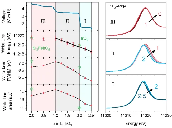
II-4-a X-ray Absorption Near Edge Structure (XANES) ... 38
II-4-b Hard X-ray Photoelectron Spectroscopy (HAXPES) ... 42
II-5 Structural evolution during cycling ... 46
II-5-a Synchrotron X-ray diffraction (SXRD) ... 46
II-5-b Neutron powder diffraction ... 48
II-5-c Extended X-ray absorption fine structure (EXAFS) ... 55
Conclusion ... 59
Chapter III. IrO3 as a Na+ host with an active oxygen network ... 61
Introduction ... 62
III-1 Synthesis ... 63
III-2 Structural Characterization ... 64
III-3 Electrochemical behavior ... 67
III-4 Anionic redox activity ... 69
III-5 Operando XRD ... 70
III-6 Long term cycling ... 76
III-7 Thermal stability ... 77
vii
Introduction ... 82
IV-1 Synthesis and characterization ... 83
IV-1-a Ion exchange... 83
IV-1-b Chemical composition ... 83
IV-1-c Structural characterization ... 85
IV-1-d Particle morphology ... 87
IV-1-e Ir oxidation state ... 87
IV-1-f Proton insertion ... 88
IV-2 The oxygen evolution reaction ... 92
IV-2-a Electrochemical performance ... 93
IV-2-b Stability during OER ... 94
IV-2-c Operando XRD – β-H2IrO3 ... 96
IV-2-d Charge compensation during OER ... 97
IV-3 Reactivity of lithiated intermediates in acidic media ... 98
IV-3-a Sample preparation ... 98
IV-3-b Ex situ characterization ... 99
IV-3-c On-line Mass spectrometry ... 101
viii
IV-4 Proton insertion as charge compensation for stable OER catalysis ... 104
IV-5 Conclusion ... 106 General conclusions ... 108 Appendix ... 112 Appendix – Chapter II ... 112 Methods ... 112 Figures ... 114
Appendix – Chapter III ... 122
Methods ... 122 Figures ... 124 Appendix – Chapter IV ... 130 Methods ... 130 Figures ... 133 References ... 142
General introduction
Producing clean and renewable energy is key to mitigating global warming and the energy crisis to come. Large efforts are invested in the development of technologies such as photovoltaics and wind turbines which allow the conversion of solar and wind energy to electricity. These technologies are intermittent in nature, therefore their integration to the grid is challenging. In order to alleviate this issue, energy storage systems must be developed in parallel. One technology which is gaining much traction thanks to its versatility and diminishing costs is the Li-ion battery (LIB). The ability to store large amounts of energy and have reasonable power capabilities is a great advantage for grid applications. Furthermore, this enables isolated power systems which rely on solar panels or wind turbines but do not have access to the grid.
In addition to solving issues concerning energy production for grid applications, the transportation sector is one of the main greenhouse gas emitters and most of the world population relies on the use internal combustion engines for individual transportation or freight forwarding. Developing alternatives to fossil fuels for locomotion is crucial for the transition to a greener planet. Although electric cars predate the internal combustion engine, their development was close to inexistent during most of the 20th century due to the availability, high energy density and ease of use of oil. In the past decade however, hybrid and fully electric vehicles have seen their way to the market and prices are dropping as the advances in battery technologies continue.
Although the energy density and reliability of LIBs have greatly improved since their commercialization in 1991 by Sony, today’s requirements are still not met and further improvements are needed. Furthermore, major concerns about the limited abundance of Li have driven the development of alternative battery technologies with namely the Na-ion technology. While it has not reached the maturity of the LIBs, there have been considerable improvements in the materials used for such sodium based systems. These developments have led to the launch of a French startup called Tiamat in 2018 which commercializes the first industrial grade 18650 Na-ion cells.
One emerging paradigm for the development of new high energy density positive electrode materials for battery technologies is the participation of lattice oxygen in the
redox processes during insertion and extraction of alkali ions in a certain family of oxides. This allows materials which exhibit such activity to increase their reversible capacity at high voltage, thus increasing their energy density. However, this usually comes at a price on the cycle life and severe performance decay is observed. While the first chapter will go further into details on this subject, the aim of this thesis is to study the structural and electronic implications of anionic redox in a model iridate host, IrO3,
for Li+ and Na+ ions. The use of cutting edge analytical techniques such as synchrotron X-ray and neutron powder diffraction (NPD) as well as X-ray absorption or photoemission spectroscopies are instrumental to probe the different aspects of such a subtle process. A firm understanding of the structural and electronic repercussions of lattice oxygen oxidation should help the scientific community in finding solutions and making these materials industrially viable.
While battery technologies are promising energy storage systems and have become dominant in transportation and portable electronics, tomorrow’s energy landscape will most likely be composed of a variety of different technologies, one of which will be hydrogen fuel cells. Indeed, using hydrogen as a fuel and controlling its recombination with oxygen to form water while delivering large amounts of energy seems like an ideal solution. However, considerable efforts have been deployed to develop efficient systems capable of producing hydrogen from water using only renewable energies but advances have been scarce in the past few decades. One major roadblock is the sluggish kinetics of the oxygen evolution reaction (OER) - counter reaction to the evolution of hydrogen - which translates to large energy penalties. The production of hydrogen can be carried out in both acidic and alkaline environments but the lowest overpotentials are obtained at very low pH. In these harsh conditions, OER catalyst materials which are composed of transition metal oxides generally dissolve during anodic polarization. The best materials today are composed of Iridium and Ruthenium with the latter being less stable and the former less active. The iridate described in this thesis presents interesting properties for OER catalysis. Indeed, its ability to uptake and deliver protons has brought new insight into the charge compensation mechanism of a long suspected hydrous iridium oxide. Furthermore, the ability to form IrO3 by oxidation of the β-Li2IrO3 in organic media has enabled the study
of a high valence iridate suspected of being the active intermediate during OER catalysis on the surface of oxides. It is important to continue the search for highly efficient
catalysts capable of lowering the high overpotentials encountered during the water splitting reaction in order to make the technology viable.
The focus of this thesis is the study of oxygen redox in the bulk of the hyperhoneycomb IrO3 host material during insertion and extraction of Li and Na as well
as on the surface of the protonated phase in acidic media. The fields concerned by this work are the Li- and Na-ion battery technologies and the electrocatalysis of the water oxidation reaction. This manuscript is divided into four chapters not including this short general introduction.
The first chapter will briefly explain the working principle of alkali ion batteries, the different host materials and their evolution during the past three decades. In the same chapter, the recent observation of a new solid state redox mechanism coined anionic redox will be explained which will introduce the following work.
The second chapter will present the study performed on the β-Li2IrO3 phase,
namely its synthesis, structural characterization, electrochemical performances, structural transitions during charge and the participation of both Iridium and Oxygen to the de/lithiation process.
The third chapter will discuss the synthesis and characterization of the β-Na1.7IrO3 phase obtained electrochemically by sodiation of the delithiated IrO3. The
structural evolution during charge and discharge are determined and the oxygen lattice is shown to participate in the desodiation process.
The fourth chapter will present the synthesis and characterization of a protonated crystalline phase obtained by cation exchange of β-Li2IrO3 in 1M H2SO4. The proton
extraction/insertion capabilities of this new phase are assessed and its activity as OER catalyst is evaluated. The structural and electronic changes occurring during OER are characterized by operando X-ray diffraction and X-ray absorption spectroscopy. The reactivity of IrO3 in acidic media is evaluated and a charge compensation mechanism is
described in order to rationalize the observations.
Finally, some general conclusions will complete this thesis with a few directions for future research in both the field of battery and the field of electrocatalysis.
Prequel to the Li based energy storage technologies
Batteries date back to the 18th century with the first electrochemical primary battery being developed by Alessandro Volta in 1799-1800.1 He first described this electrochemical cell in a letter as composed of alternating discs of different conducting metals such as Zinc (Zn) and Copper (Cu) each separated by cloth soaked in a solution of salt water and which produces electricity without having to charge it (as opposed to the Leyden jar, antique capacitor technology of the time). In his letter, he often compares his device to the torpedo fish or the electric eel and therefore expresses his will to call it the “organe électrique artificiel” (artificial electric organ). However, it is most known by the name of voltaic pile in reference to him and to the device which is nothing more than a pile of metallic discs and cloth. Since then, electrochemical storage systems have greatly evolved and have become crucial to the positive transition of societies energy landscape to a more sustainable future. These evolutions have been marked by the fundamental understanding of the redox reactions taking place in such electrochemical cells and to both intentional and serendipitous breakthroughs throughout the past two hundred years.
One of the pivotal events which has enabled the development of today’s high capacity electrochemical storage technologies was the discovery of Lithium by Johan August Arfwedson and Jöns Jakob Berzelius in 1817-18182 which was later isolated by William Thomas Brande in 1821 and who described it at the time as “a brilliant white and highly combustible metallic substance”. Interestingly, he also states that “Pure lithia is very soluble in water, and its solution tastes acrid like other fixed alcalis” which illustrates the lack of personal safety considerations of the time.3 It was later understood that its flammability was due to its reactivity towards the ambient moisture which produced hydrogen gas. Indeed, its electrochemical potential was determined by Gilbert Lewis and Frederick Keyes in 1913 and found to be “the highest electrode potential hitherto measured",4 attributing it the highest reducing power of all elements. Note the use of the Nernst–Lewis–Latimer convention (commonly referred to as the American convention) which defines the potential as that of the half reaction measured against a standard hydrogen electrode (SHE) which sign depends on the setup of the measurement as opposed to the Gibbs–Ostwald–Stockholm convention (commonly referred to as the European convention) which will be used in this thesis and that considers the potential
as that of the electrode which is invariant in sign.5 In the European convention, a reducing agent has a lower potential than an oxidizing agent, hence the potential of lithium is given as -3.04 V vs SHE. In addition to this incredibly low potential of -3.04 V versus the standard hydrogen electrode, it is the lightest solid element under standard conditions giving it the highest specific energy of all alkali metals. Higher specific energies can be attained by divalent and trivalent elements such as Beryllium or Aluminum but issues of toxicity (for Beryllium), solvation and diffusion arise which make them, as we will see, more difficult to use for industrial energy storage applications.
Before the discovery and the isolation of Lithium, the English scientist Sir Humphry Davy had managed to isolate sodium which was described by Jules Verne’s emblematic character – Captain Nemo in 20,000 Leagues Under the Sea – as “the most electromotive element of all”. While this is not true for sodium, it is more so the case for lithium which has driven intense academic and industrial research efforts for the past fifty years. In any case, this incredible foresight from a science fiction author of the 19th century is quite remarkable.
I-1 Lithium batteries
Owing to its light weight (6.94 g/mol), low potential (-3.04 V vs SHE) and high theoretical capacity (3862 mA·h/g), lithium was early on believed to have great potential for primary and secondary (rechargeable) battery systems but its reactivity was both the motivation and the roadblock. Finding a stable electrolyte was an arduous task and one that took over 20 years between the 50’s and the 70’s and was started by the seminal work of Harris and his thesis called “Electrochemical studies in cyclic esters”.6 His study of the transport properties of different ions in organic solvents paved the way to the finding “stable” electrolytes for Li metal plating which in turn would enable the development of energy storage systems. It was later understood that the aforementioned solvent’s stability was in fact the result of a parasitic reaction. Indeed, in contact with lithium some organic solvents such as carbonates would react and form a passivation layer which would act as an ionic conductor and an electronic insulator, thus limiting further degradation of the electrolyte. This complex layer was coined by Peled as the “solid electrolyte interphase” (SEI).7 It is on account of this SEI that primary systems
using lithium as negative electrode were able to display long shelf lives of 10 years or more.8
Secondary batteries were developed in the late 70’s early 80’s with the increasing understanding of insertion chemistry thanks to researchers such as Stanley M. Whittingham and John B. Goodenough and the discovery of Li hosts such as the layered structure of sulfides (TiS2, ZrS2, MoS2…), selenides (TiSe2, ZrSe2, MoSe2…)9 and
lithiated oxides (LixWO3, LCO…)10,11 which could reversibly uptake/deliver Li+ ions
following the half reaction (1) and serve a positive electrodes in cells using Li metal (2) as negative electrode and an organic electrolyte (Figure I.1). This attracted much attention and craze over the possibility of making high energy density rechargeable lithium batteries. However, due to the fact that a battery is a closed system in which the consumption of the electrolyte by the parasitic reaction leading to the formation of the SEI over several plating/stripping cycles strongly hindered the development of these rechargeable systems. In addition, the SEI leads to inhomogeneous nucleation of lithium metal and the formation of preferential growth sites which in turn leads to the formation of Li filaments called “dendrites” as represented in Figure I.1 bottom panel. These dendrites can cross the separator and create short circuits which often lead to thermal runaway and, due to the volatile and flammable nature of the organic solvents used, to an explosion. While some companies still pursued the Li metal battery technology, the commercialization in 1988 by Moli Energy of a system based on MoS2 as the positive
electrode and using Li metal as the negative electrode which led to a massive recall of cell phones in Japan due to numerous fire incidents marked the end of the infatuation with Li metal negative electrodes.
𝑀𝑆2+ 𝐿𝑖++ 𝑒− = 𝐿𝑖𝑀𝑆2 (1)
Figure I.1 (Top) Schematic of a Lithium battery with on the left the metallic lithium negative electrode, on the right the transition metal (TM) sulfide of oxide layered material and the separator with electrolyte between the two. In this simplified schematic view, only the Li+ cations are shown in the electrolyte but there is also the solvent molecules and the counter ions. (Bottom) Schematic representation of a cell after charging and the formation of dendrites which cross the separator to reach the cathode.
A few years later, a solid polymer electrolyte based system using Li metal as anode was commercialized but the technology was reserved for niche application such as stationary energy storage for telecommunication companies. Recently, Paris has been the testing grounds for this technology in shared vehicles called “Autolib’” which are developed by Bolloré under the name BlueCar. This technology requires heating the cells around 60°C in order to improve Li+ diffusion within the polymer membrane and to maintain the proper management of dendritic growth. While this is acceptable for shared cars and public transportation applications it is poorly adapted to individual car ownership. The test was a success in terms of proving the technology viability but
unforeseen costs and underuse by the public far below the expectations led to a substantial debt and brought the project to an early grave in August 2018.
Academic and industrial research efforts are still deployed today in order to find solutions to the inherent risks of using lithium metal as a negative electrode but no mature technology is expected in the next few years. The most promising lead is the all solid state batteries which are very similar to the lithium metal polymer systems but with an inorganic electrolyte instead of the organic polymer. However, interfacial issues arise from the volume variations of both the lithium negative electrode and the insertion cathode. Due to the inherent risks of using lithium metal as anode, another promising technology surfaced near the end of the 80’s which led the revolution of the LIBs.
I-2 Li-ion batteries (LIBs)
During the 80’s the concept of lithium rocking chair batteries was developed which are known today as LIBs. The first mention of such systems was made D. Murphy and B. Scrosati in the late 1970’s where the authors explain that the use of insertion materials, or host materials, for both the positive and the negative electrodes could solve the issues concerning the cycling of Li metal anodes.12,13 Shortly after, examples of such systems using LiWO2 as negative electrode and positive electrodes
composed of TiS2, WO3 or NbS2 were demonstrated14 but owing to the necessity to
prelithiate the negative electrode prior to assembling the final cell and the poor diffusion of Li+ into these hosts, they were considered too costly and inefficient.
Layered structures such as the sulfides are uncommon in oxides due to the high electronegativity of oxygen and the important coulombic repulsions ensuing between the negatively charged layers. Nevertheless, it is possible to obtain layered structures in oxides with alkali ions in between the MO2 sheets, thus screening the negative charges.
The discovery in 1980 by John Goodenough of LiCoO210 (LCO) and the subsequent
discovery of several other LiMO2 compounds with M = V, Cr, Ni15 and Mn which could
reversibly release and uptake lithium into their structure (3) was key to the development of today’s LIBs. The idea to use these lithiated compounds as the initial source of Lithium was presented by Auborn and Barberio in 1987 when they demonstrated the possibility of using as synthesized LCO as positive electrode and MoO2 or WO2 as
negative electrode without any prior steps.16 However, the overall capacity of such systems was not competitive due to the heavy TM ions in both electrodes.
𝐿𝑖𝑀𝑂2 = 𝑀𝑂2+ 𝐿𝑖++ 𝑒− (3)
The best negative intercalation electrode material was quickly understood to be graphite due to its relatively high capacity (372 mA·h/g), fast ion transport, low weight, low volume expansion during lithiation and reduction potential very close to that of lithium metal plating. Another good anode material is lithium titanate which was reported to have no strain induced by lithiation or delithiation.17 However, while its relatively high working potential (1.55 V vs Li) makes it very stable with repect to the carbonate electrolyte solution, it also lowers the overall tension of the battery which is a high price to pay. Similarly to lithium metal, a stable SEI can be formed on the surface of carbonaceous anodes, protecting the electrolyte from further degradation. However, lithium intercalation into graphite is accompanied by co-intercalation of propylene carbonate (PC), most commonly used electrolyte during that period, which led to exfoliation of the graphene sheets and loss of performances. It wasn’t until discovering that the addition of ethylene carbonate (EC) into the electrolyte largely diminished this detrimental co-intercalation that practical applications became a reality. The first paper to evidence the beneficial effect of EC was published in 199018 and the first commercialized cells were brought to market in 1991 by Sony which used graphite as negative electrode, LCO as positive electrode and an EC containing electrolyte.
Figure I.2 « Rocking chair » or Li-ion battery (LIB) with two intercallation compounds at each electrode. The negative electrode is graphite and the positive electrode is a lithiated TM oxide. On charge, under potential or current control, Li+ is extracted from the positive electrode commonly called cathode in the battery field and flow through the electrolyte to the negative electrode, commonly called anode. On discharge, the reverse reaction occurs spontaneously and Li+ flows from the anode to the cathode through the electrolyte while electrons flow through the outer circuit creating a current.
Although the first commercialized LIB used LCO as cathode material, the high price and toxicity of Co were very early on a concern for commercialization and research was focused on finding materials with cheaper TM. Two main oxide families were pursued : the spinel LiMn2O419 and the olivine LiFePO4.20 While much research
has been carried out on these two structures with different TM compositions, the focus of this thesis lies with the evolution of the layered oxide family derived from LCO.
I-3 Improving the capacity of LIBs
As explained above, the cost and toxicity of cobalt was a real driving force for researchers to find materials that could attain performances similar to or better than LCO using more environmental friendly and earth abundant elements. Furthermore, only ~50% of the theoretical capacity (135 mA·h/g out of 275 mA·h/g) of LCO can be cycled reversibly which represents a significant amount of inactive capacity. Thus, LiNiO2
(LNO) appeared to be advantageous as nickel is cheaper than cobalt, the working potential of LNO is slightly below that of LCO leading to less reactivity towards anodic decomposition of electrolyte and it has a higher capacity (> 150 mA·h/g). However, it
was quickly shown that the thermal instability of LixNiO2 presented major safety
drawbacks, making its implementation unwise.21 Nevertheless, cation substitutions such as LiNi(1-x)CoxO2 decreased the thermal instability while slightly increasing the capacity
compared to LCO (~140 mA·h/g). The best thermal stability was demonstrated by LiMn2O421 and although this is not a layered compound it suggested that Mn could be a
good substitution element for improving safety but also cost and toxicity. In addition, the demonstration of a cyclable LiMnO222 and the feasibility of a solid solution of
composition Li(Ni(1-x-y)MnxCoy)O223 with varying performances depending on the values
of x and y opened the door to a proliferation of papers on a variety of possible combinations in order to obtain the highest performances with the lowest costs. Other cations were investigated such as Al3+, Ti4+ and Mg2+ and others; 24–26 however, due to the extensive research on the subject we will focus on the family of oxides called NMC for Nickel-Manganese-Cobalt.
In 2001, T. Ohzuku and Y. Makimura reported the now well known “NMC 111” which has equal parts of each TM and can attain a reversible capacity of 150 mA·h/g with a cutoff voltage of 4.2 V vs Li.27 During that same year, J. Dahn’s group published a paper on Li[NixCo(1-2x)Mnx)O2 for which x = 1/4 and 3/8 which stated that capacities
of 160 mA·h/g and 150 mA·h/g respectively could be obtained with a cutoff potential of 4.4 V.28 For x = 3/8, if the high voltage limit was reduced to 4.2 V, the reversible capacity was closer to LCO with 136 mA·h/g. However, they measured the stability of each compound at different states of charge and compared with LCO. It was found that both materials performed better and presented definite advantages with respect to safety in addition to those in terms of cost and toxicity brought by Mn. It is today’s understanding that the capacity of these materials is mainly brought by Ni and to a lesser extent to Co which rather brings rate capability by improving electronic conductivity and that Mn has a stabilizing effect with respect to thermal decomposition.29,30 While the presence of Ni in the Li interlayer in non-stoichiometric Li1-xNi1+xO2 but also at high
states of charge due to cation migrations in LNO was determined to be the cause of capacity fading observed in these cathode materials,31 it seems substitution by Co and Mn hinders this degradation path. Thus, one of the best performing electrodes used today for EV applications is the NMC materials but large efforts are invested in increasing the amount of Ni in order to increase the capacity while avoiding the thermal instability and capacity fading of pure LNO. Today’s market for EV applications is for
the most part composed of NMC 111 and 532 but higher Ni content materials such as 622 and to a lesser extent 811 capable of delivering as much as 200 mA·h/g are seeing their way to the market as well and seem to be the most promising cathode materials for EVs in the near future.29,32
I-4 Outgrowing classical cationic redox
As we have seen in previous sections, the energy density of cathode materials has improved during the past decade and devices are becoming increasingly reliable. Nevertheless, it seems we are approaching the limits of the best known materials and innovations that disrupt the field are needed. In recent years, such a paradigm shift has occurred with the discovery of what is now well established as anionic redox. It all started with Amatucci et al. showing that full delithiation of LCO to obtain CoO2 was
possible but that Co was only partially oxidized in the fully delithiated compound.33 It was quickly hypothesized that oxygen must also be, in some part, capable of being oxidized during delithiation.34,35 Evidence of O-O distance shortening in LCO at high states of charge further suggested that oxidation of the lattice oxygen was a relevant charge compensation mechanism during delithiation.36 However, it wasn’t until the discovery of a new family of oxides with surprising energy densities known today as Li-rich NMC that this theory really started making sense.
These Li-rich materials of composition Li1+xM1-xO2 with x ≤ 1/3 (M = Ni, Mn
and/or Co), also written Li2MO3 for x = 1/3, can be obtained by substituting the TM
from LiMO2 for additional Li in the TM layers. Such systems, with M = Ru or Mo, were
studied early on by James and Goodenough in 1988 as cathode materials due to their structural similarities with the LiMO2 phases.37,38 Indeed, Li2MO3 compounds can adopt
a rocksalt derived layered structure in which Li3 and LiM2 sheets are alternated and
separated from each other by O layers. Due to the size difference between Li and the TM, a specific ordering can be achieved describing a honeycomb motif. While these compounds intuitively could attain higher capacities thanks to the increased Li/TM ratio, the limitation was thought to come from the highest oxidation state of the TM. It wasn’t until the successful cycling of Li2MnO3 in which Mn is in octahedral coordination with
a +IV oxidation state and for which the +V state is unlikely, that questions about the origin of the high capacity of this material started arising. The capacity and cyclability
was initially thought to be due to the loss of Li2O from the structure at high potential
and the formation of a biphasic system with LiMnO2 which was redox active and
stabilized by the presence of Li2MnO3 domains.30 This was the beginning of a new wave
of materials research which aimed at developing composite materials of composition xLi2MnO3-(1-x)LiMO2 with M = Ni, Mn, Co and other TMs which were later
understood to be solid solution compounds.
Indeed, in 2002, Dahn and coworkers described the synthesis of a family of compounds of composition Li[NixLi1/3-2x/3Mn2/3-x/3]O2 with x = 1/2, 5/12, 1/3, 1/4 and
1/6 with intriguing electrochemical properties. It is important to bear in mind that in all the compounds, Mn is maintained in the +IV state whereas Ni is either in +II or +III state and is the only redox active TM. When limiting the potential window between 2.0 V and 4.0 V, the voltage composition curve shows a smooth plateau on charge and discharge with no significant polarization, capacities close to the theoretical values and good reversibility are obtained. Surprisingly, when the upper cutoff voltage is increased to 4.8 V, a second smooth voltage plateau is observed on charge with a slope-like discharge with a large irreversible capacity. X-ray diffraction allowed to determine that the irreversible capacity loss was due to the loss of oxygen from the structure.39,40 While this irreversible loss of oxygen was cause for concern, the reversible capacities could attain 230 mA·h/g with a voltage window between 2.0 V and 4.8 V. Further substitution of Mn by some amount of Co led to what are now known as the Li-rich oxides which can deliver up to 270 mA·h/g (Figure I.3).41,42
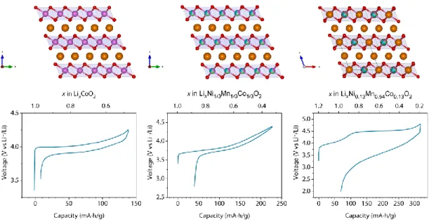
Figure I.3 Evolution of Layered oxide cathode materials structure/composition and their electrochemical behavior. a) LCO composed of alternating layers of Co (pink) and Li (orange) separated by layers of oxygen (red). The electrochemistry is very reversible and stable. b) NMC 111 with a structure similar to LCO with partial substitution of Co for Ni (green) and Mn (blue). The electrochemistry is quite similar between the different NMC materials although capacities vary (extracted from Deng et al. 201043). c) Li-rich NMC in which the TM are partially substituted for Li resulting in a honeycomb motif. The electrochemistry is characteristic of Li-rich compounds with two distinct plateaus on the first charge and a slope discharge44.
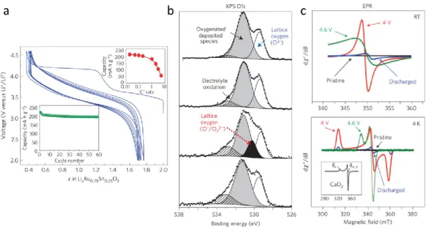
Figure I.4 Reversible anionic redox evidenced by XPS and EPR in Li2Ru1-ySnyO3. a) Voltage composition curve for Li2Ru0.75Sn0.25O3 showing a staircase profile on first charge followed by an S-shaped discharge which is retained on subsequent charge/discharge cycles. b) XPS O 1s spectra at different states of charge and discharge with from top de bottom : pristine, charged to 4.0 V, charged to 4.6 V and after full discharge back to 2.0 V. The different signals obtained by deconvolution of the signal are explained on the figure. c) EPR spectra at room temperature (top) and at 4 K (bottom) showing the appearance of a sharp signal at full charge signifying the presence of paramagnetic electrons on oxygen and therefore of oxidized species. Reproduced from Sathiya et al., Nature Materials (2013).
While several hypotheses on the origin of the extra capacity were stipulated during the following years (TM over-oxidation, loss of Li2O or O2 accompanied by the
formation of spinel-like phase on the surface, Li/H ion exchange…), it wasn’t until 2013 that a solid explanation could be demonstrated through the study of model materials such as Li2Ru1-yMyO3 (y = 0-1) with M = Sn, Ti, Mn.45–47 Indeed, these compounds
adopt a similar layered structure to the Li-rich NMC with honeycomb layers of LiM2
alternated with pure Li layers in a dense stacking of oxygen. Their advantage is their simplicity with regards to the redox active species and their similar electrochemical behavior to the Li-rich NMC materials, namely the first charge composed of two well defined voltage plateaus followed by an S shaped discharge after the second plateau leading to slope-like subsequent charge/discharge cycles. Indeed, in Li2Ru1-ySnyO3, only
Ru is a redox active cation and its oxidation which can be followed either by X-ray photoemission spectroscopy (XPS)45,48 or by X-ray absorption near edge structure
(XANES).49 However, the first signs of anionic redox were detected by electron paramagnetic resonance spectroscopy (EPR) and XPS on the O 1s level (see Figure I.4). The appearance of a new component around 531 eV on the second plateau was assigned to an oxidized lattice oxygen O- environment which was supported by density functional theory (DFT) calculations.45,47,48 These oxidized oxygens were suspected to form “peroxo-like” species with shortened O-O distances however, due to the lack of long range ordering they could not be evidenced by XRD. It wasn’t until their detection by XPS and their visualization by transmission electron microscopy (TEM) and (NPD) in α-Li2IrO3 that this was confirmed (see Figure I.5).50 Finally it was concluded that
oxygen redox could bring additional capacity which brought new hope to the field of materials research for higher energy density cathode materials.30
Figure I.5 Evidence and visualization of short O-O distances on fully charged α-Li2IrO3. a) Voltage composition curve of α-Li2IrO3 and α-Li2Ir0.75Sn0.25O3. b) XPS O 1s spectra of α-Li2IrO3 at OCV, 3.9 V, 4.6 V and after one charge/discharge cycle. The components obtained by deconvolution of the spectra are as follows: blue for the O2- lattice oxygen, pink for the O n-lattice oxygen, vertically and diagonally hashed for the surface adsorbed species. c) HAADF-STEM image of the fully charged α-Li2IrO3 with the integrated intensities shown below evidencing the shortened O-O distances. Reproduced from McCalla et al., Science (2015).
This comprehension was then extended to the more complex but useful Li-rich NMC51,52 and a plethora of publications on anionic redox as a strategy to increase energy density of oxide cathode materials has been published.30,44 However, long term performance decay such as voltage fading53,54 and capacity loss over cycling hinder the integration of such Li-rich compounds in batteries for EV applications.
I-5 Origin of performance decay in Li-rich layered oxides
As explained above, the Li-rich layered oxide (LrLO) cathodes display impressive capacities but also steady decay of energy density over cycling coming from both the loss of capacity due to oxygen release on the first cycle at high potential40 and the voltage fading53 which origin will now be discussed. Once again, the reason for the diminishing Li+ de/intercalation potential over cycling was solved through the study of the Li2Ru1-yMyO3 (with M = Mn, Ti, Sn) model compounds. It was observed that the
compound containing Ti shows superior voltage decay over cycling compared to the Sn substituted phase (Figure I.6). Post mortem TEM images clearly show that a large amount of Ti ions migrate irreversibly to tetrahedral sites within the Li layer in order to stabilize the Li poor structure. While this trapping of small ions is also observed in the Li-rich NMC phases, the substitution of Ru by larger spectator ions such as Sn is found to considerably mitigate the voltage decay and TEM images display substantially less ion migration which can be rationalized by comparing the ionic radii (𝑟𝑇𝑖4+ ≪ 𝑟𝑆𝑛4+).46 However, the substitution of active redox centers by inactive ones comes at the expense of energy density and was therefore considered an undesirable strategy although it served its purpose by uncovering the mechanism of voltage decay in Li-rich oxides.46 Structural defects as the origin of the loss of lithium extraction potential is now well established55–59 and many strategies with varying degrees of success are pursued in order to solve the issue either by substitutions,60–65 by controlled formation of oxygen vacancies/cation site defects66–68 and by surface doping coating.69–74
Figure I.6 Voltage composition profiles for the first 100 cycles of a) Li2Ru0.75Sn0.25O3 and b) Li2Ru0.75Ti0.25O3 showing the voltage decay over cycling (adapted from Sathiya et al. Nature Materials, 2013)
While the process of delithiation/lithiation through anionic redox in these LrLOs is well recognized by the community, its crystallographic and electronic structural implications are still not fully resolved and require both theoretical and experimental work in order to paint the complete picture which would allow us to determine its true viability for applications such as portable electronics and EVs. The current understanding of the origin and implications of anionic redox will now be developed.
I-6 Origin of anionic redox
In order to understand the origin of anionic redox, it is essential to have a good description of the electronic structure of the studied oxides. Due to the high covalency of the TM-O bond compared to the Li-O bond, a simplified description of the electronic structure of lithiated oxides can be constructed based solely on the TM-O interactions.57–
59 The TM orbitals involved in bonding with ligands are the nd orbitals and those for O
are the 2p orbitals as the 2s levels lie to deep for any overlap to take place. In the materials relevant to this discussion, all TM are in octahedral sites and the nd orbitals will be considered as split into stabilized t2g and destabilized eg orbitals with a gap Δ. In
addition, these transition metal oxides are known Mott insulators with a splitting of the TM bands (U) due to electrostatic repulsions between unpaired electrons.
Three different compositions with their structures (excluding Li+ ions) and band diagrams are depicted in Figure I.7. First we will discuss the case of the classical LiMO2 structure such as LCO, secondly we will increase the O/M ratio and describe the
electronic structure of the LrLOs (Li2MO3). Finally we will comment on a yet higher
O/M case, the Li3MO4 type compound with M = Ir and/or Ru which has been studied as
Figure I.7 Structures and simplified band structures of different lithiated TM oxides of compositions a) LiMO2, b) Li2MO3 and c) Li3MO4. The blue and red spheres represent the TM and oxygen ions respectively and the yellow filled rectangles highlight the O environment with respect to the TM. The Hubbard splitting is shown with a blue double arrow and the charge-transfer gap with an orange double arrow. The bands represented in blue imply orbitals that are mainly localized on the TM, in red on O and in grey both on O and TM.
In the layered LiMO2 structure, each oxygen anion is bonded to three
neighboring TM cations forming (MO) bonding states and (MO)* antibonding states as depicted in Figure I.7 a). In this scenario, if the nd orbitals of the TM lie much higher in energy then the O 2p orbitals as is generally the case, the (MO)* states are localized on the cation and when the material is oxidized (i.e. lithium is extracted) on charge and electrons are taken from these states, it is called cationic redox as the holes are localized on the TM cation orbitals. When these states are empty, further lithium withdrawal would lead to structural degradation as it would empty the bonding states.
However, in structures where the M/O ratio is higher the 1/2, such as in the LrLOs (Li2MO3), non-bonding oxygen 2p states are present as represented by a thin red
band at the top of the (MO) band in Figure I.7 b). In this scenario, two cases can be differentiated: (i) if the TM orbitals lie high above the O 2p states or in other words U < Δct, the electrons are first withdrawn from the (MO)* band which is again considered as
and give rise to what is known as anionic redox. This process is generally thought to entail a distortion of the MO6 octahedra in order to stabilize the holes on oxygen by the
formation of O-O states and which, if pushed too far, can lead to oxygen release. A good example of this degassing is the Li-rich NMC compounds which have been shown to evolve O2 during the high potential process (anionic redox portion). (ii) If the (MO)*
states lie close to the O 2p non-bonding states, a distortion can give rise to the hybridization of these two states and the formation of M(OO) σ, π, π* and σ* states which should stabilize further the holes on oxygen type states and thus increase reversibility. In both cases, the maximum amount of charge that oxygen is capable of delivering before the release of molecular O2 in these compounds has been theoretically
determined as 1/3 e-/O.59 Furthermore, structurally this will lead to the formation of distorted octahedra and short O-O distances which have been termed as “peroxo-like” species.59 It is important to bear in mind that, while these are considerably shortened O-O distances for these compounds, they are far from the true peroxide bond length and their spectroscopic signatures are not necessarily comparable to Li2O2 species as we will
see.
As mentioned above, the case of Li3MO4 with M = Ir and/or Ru were recently
studied to attempt to push anionic redox further and assess its limits.75,76 In Figure I.7 c), the structure represented is that of Li3RuO4 as it has a Li/Ru ordering within the layers
whereas in the case of Li3IrO4, Li and Ir are completely disordered and makes the
illustration more difficult. It is clear that, while the ordering/disordering will most likely lead to differences in performances, the simplified band structure will most likely be similar with namely the presence of more O 2p non-bonding states as can be deduced by the mean oxygen environment. In this particular case, as Iridium is a 5d TM with a high oxidation state (+V), the (MO)* states are most likely closer to the O 2p non-bonding states and it has been demonstrated that upon charging (Li+ extraction) holes are localized mainly, if not solely, on the oxygen state. This anionic redox allows the reversible removal of up to two Li+ while a third one leads to O2 evolution and the loss
of long range ordering to form an amorphous iridate of composition IrO3 as deduced by
TGA-MS.75 In the case of M = Ru, the dissolution of Ru mitigates the gas evolution but is equally detrimental.76 Either way, increasing the O/M ratio seems to favor the extraction of lithium through oxygen redox rather than TM redox and 0.5 e-/O is the highest amount of charge that oxygen is capable of delivering before the release of
molecular O2 in the case of Li3IrO4 which differs significantly from the theoretical limit
attributed to the Li2MO3 family of compounds (1/3 e-/O) suggesting a higher amount of
reversibility is attainable by tuning structure and composition.
Another class of materials not mentioned thus far but which has concentrated significant research efforts is the disordered rocksalt Li2MO3 compounds. Indeed, while
composition is of course the obvious parameter on which chemists have played with in order to increase the capacity of cathode materials, a high degree of order was always desired in order to increase Li+ diffusion until the discovery of the surprising yet interesting behavior brought upon by the disordering of cations within the structure of Li2MO3 compounds.68,77,78 While these display large amounts of reversible anionic
redox activity they will not be discussed as of now.
I-7 Na-ion batteries (NIBs)
Sodium based systems have followed a parallel path to Lithium based systems with namely the study of insertion chemistry in the 70’s using sulfides and in the 80’s using oxides such as NaCoO2 (see Figure I.8 a). However, the penalty incurred by the
lower potential (-2.71 vs SHE) of sodium and its higher molar mass (22.99 g/mol) limited the energy density of insertion compounds compared to those inserting Lithium as illustrated by the cycling profile of LCO compared to NaCoO2 shown in Figure I.8 a).
Furthermore, Na containing compounds tend to exhibit higher reactivity to ambient moisture, making their use more difficult than their lithiated counterparts. In addition, due to the higher solubility of the sodium salts and decomposition products of the electrolyte at low potential, the use of Na metal as anode was impractical and the sodium batteries were not pursued for very long. In fact, research on sodium based systems nearly vanished until recently due to geopolitical and environmental concerns about the limited amounts of Lithium available on earth (see Figure I.8 b) which has boosted considerably the interest in Na-ion batteries.
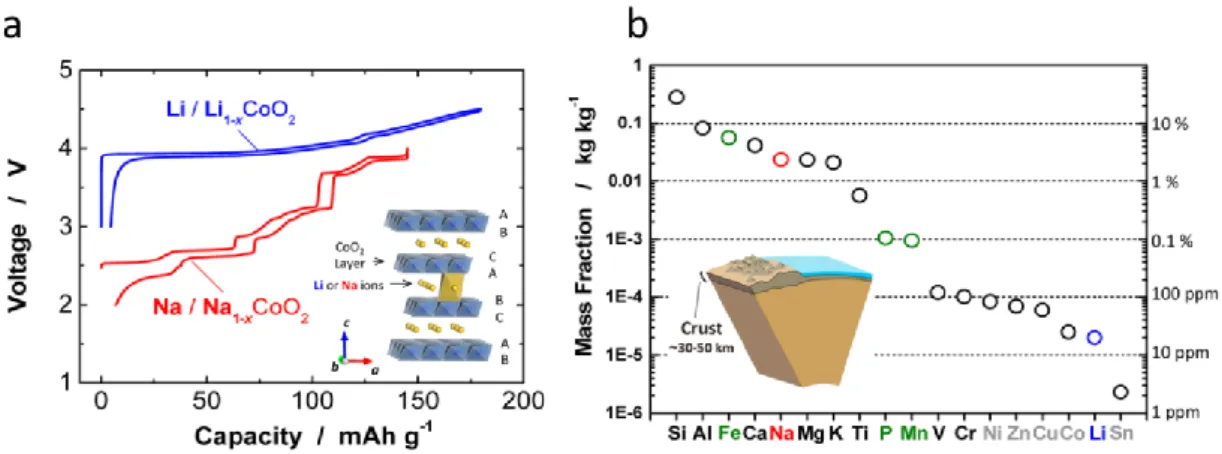
Figure I.8 a) Voltage capacity profiles for LiCoO2 and NaCoO2 with the layered ACoO2 (A = Li or Na) structure in inset. b) Abundance of elements in earth’s crust. Reproduced from Kubota et al. Chemical Reviews (2014).79
In the early days of research on Na-ion batteries, the major concern was finding a proper negative electrode as graphite could not be used due to its inability to reversibly insert Na. The turning point for these systems was the discovery of a “hard” carbon (that is to say non graphitizable) capable of delivering around 300 mA·h/g of capacity by sodium de/insertion, hence nearing that of graphite in LIBs.80,81 While this did not solve the energy density issues (compared to LIBs), it did enable a new wave of enthusiasm for NIBs and today’s research is, again similarly to the LIB, focused on developing high energy density cathode materials. Today’s stellar material is a polyanionic compound composed of vanadium phosphate of formula Na3V2(PO4)2F3 which can deliver up to
110 mA.h/g after 100 cycles.82 However, the use of toxic vanadium is undesirable when it comes to large scale applications and finding materials that make use of safer and more environmental-friendly TMs is an important driving force for the materials research community.
Since the NIB community has often been inspired by the LIB research, the recent discovery of anionic redox as a means to increase energy density is of great interest to researchers working on sodium insertion materials. Recent reports of such activity in Na-ion cathode materials have boomed in the past couple of years. However, similarly to the Li insertion compounds, the structural implications of such anionic redox are not well established yet.
Conclusion
In this chapter we have seen the evolution of the Li-ion technology with the different historical events that have led to today’s high energy systems. Although the capacities have increased steadily in the past decades, there are still some important limitations that must be pushed back in order to truly earn our independence from fossil fuels and take full advantage of renewable energy sources such as solar or wind.
The Li-ion technology is the most promising for portable electronics and electric transportation and while the automotive industry is pushing hard on the development of electric vehicles, the requirements are still not met in terms of range and lifetime. The Li-rich oxide cathodes represent a significant improvement in energy density compared to the state of the art layered materials but substantial roadblocks still hinder their integration. In recent years, the oxygen redox mechanism has been thoroughly investigated and important efforts are deployed to develop chemical and engineering solutions to mitigate the inherent issues surrounding it. However, questions still remain about the structural implications of anionic redox and the structure/property relationship. The most studied materials exhibiting a redox active oxygen network mainly crystallize in a layered structure and show very similar electrochemical behaviors. The development and investigation of novel structures could lead to a better understanding of solid state anionic redox and to more stable electrode materials. Interestingly, materials having a disordered structure, meaning that cations are randomly distributed within the oxygen network and therefore increasing the dimensionality of the TM network, have shown some interesting electrochemical properties at 55°C. While the layered structures unanimously display a drastic change of their electrochemistry after the first charge, these completely disordered structures retain their initial electrochemical profile although oxygen redox leads to large polarization issues which exceed those observed in the ordered layered oxides.68,77,78,83
The aim of this thesis is the study of a tridimensional IrO3 framework which has
a redox active oxygen network with an initial voltage profile which is retained over cycling. This framework can accommodate Li+ and Na+ ions as well as H+. While the protonated phase displays poor performances in terms of reversible proton insertion, it
has shown some interesting activity as OER catalyst. The next chapter will describe the work carried out on Li+ insertion into the IrO3 framework.
Chapter II. Structural and electronic implications of
II-1 Introduction
In this chapter, we will discuss the effect of increasing dimensionality of the host structure on the electrochemical performances of Li-rich layered oxides. Fortunately, the lithiated iridates are an amazing playground in terms of structure and composition. Li2IrO3 crystallizes in three different polymorphs84,85 named , and , which are
shown in Figure II.1. All derive from the rocksalt structure, with a dense packing of the oxygen layers (ABCABC stacking). The form is a typical layered structure with alternating layers of composition Li3 and LiIr2. The LiIr2 layers are organized in a
honeycomb type structure with LiO6 octahedra enclosed in a hexagon formed by IrO6
octahedra linked together through edge sharing (see Figure II.1). β-Li2IrO3 is built on
edge-sharing IrO6 octahedra that form a tridimensional matrix into which Li ions occupy
all available octahedral sites as shown in Figure II.3 a. The structure can accommodate Li migration via corrugated interconnected paths as supported by a bond valence landscape calculation shown in Appendix Chapter II. Figure 1.
This chapter is composed of six sections, which are organized as follows. The first will describe the synthesis and structural characterization of the β-Li2IrO3 phase,
namely through the use of diffraction techniques and electron microscopy. Then the electrochemical behavior of the hyperhoneycomb iridate will be investigated by galvanostatic cycling with potential limitation and we will discuss the effect of different cutoff voltages on its performances. In order to probe the redox active species – Ir or O – during cycling, techniques such as X-ray absorption and X-ray photoelectron spectroscopies have been used and the results will be presented in light of the electrochemical performances. The different structural implications of the delithiation processes will then be explored using operando and ex situ diffraction measurements using synchrotron X-rays and neutrons as well as EXAFS. Finally, a brief summary of the overall findings with a discussion around the structural and electronic implications of anionic redox during delithiation of the β-Li2IrO3 will conclude this chapter.
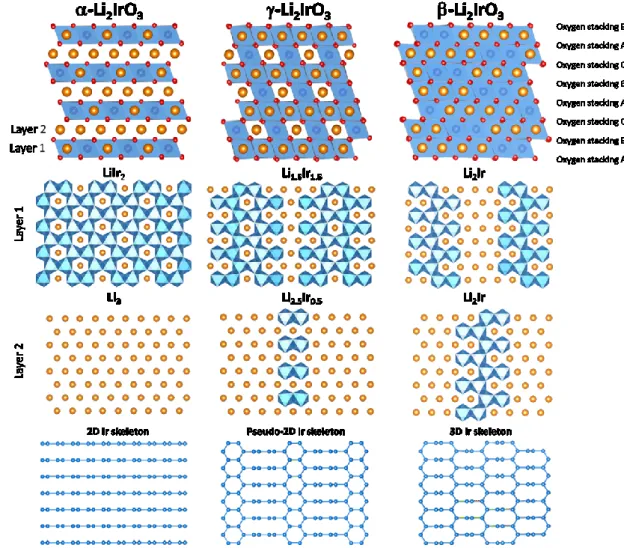
Figure II.1. Structures of the α, γ and β-Li2IrO3 polymorphs. From top to bottom: General view of the structure highlighting the ABCABC oxygen dense packing with cations (Li and Ir) sitting in octahedral sites. O is red, Li is orange, and IrO6 octahedra are colored in blue. The individual layers are shown below with their chemical composition. The bottom part only shows the Ir-Ir bond skeleton to highlight the dimensionality of the polymorphs, and the way Ir atoms are displaced from the α structure to generate the γ and β structures.
II-2 Synthesis and structure
II-2-a SynthesisIn the past, the β-Li2IrO3 polymorph has been synthesized by repetitive annealing
at temperatures above 1000°C (or prolonged annealing under O2) of the layered
polymorph. However, this synthesis route is both energy intensive and poorly reproducible as annealing times to achieve single-phased materials required either 3 days or one month. In any case, the β-Li2IrO3 could only be obtained with particle sizes
above a few microns and the recent report of a new synthesis route for large single crystals of both alpha- and β-Li2IrO3 by a separated educts vapor transport process86 was
an impetus to design a faster and more reproducible route to synthesize polycrystalline β-Li2IrO3. Indeed, the vapor transport process relies on the formation of gaseous IrO3
and LiOH which allows the formation of large single crystals. In this logic, the powders were mixed but not compacted into a pellet and Ir was added in excess to increase the IrO3 vapor pressure.
Hence, different Ir/Li ratios were tested in order to find the optimal synthesis conditions. It was found that an excess of Ir was required to preferentially form large particles of β-Li2IrO3 instead of a fine powder composed of α polymorph. After some
optimization (see Appendix Chapter II. Figure 2), Ir black and Li2CO3 in a 1/0.9 ratio
were mixed by hand grinding the powders in an agate mortar, inserted into an alumina (Al2O3) crucible. In order to increase the vapor pressure of IrO3, an alumina lid was
placed on the crucible. To confirm the hypothesis that covering the crucible increases the vapor pressure of both Ir and Li, half of the precursor batch was added to a crucible of same size but without covering. These crucibles were then placed in a box furnace and heated at a rate of 3°/min to 1000°C and held at this temperature for 24 hours after what, the furnace was allowed to cool to room temperature without control of the rate. Visually, both systems showed important differences namely the powder from the covered crucible was glistening with visibly large particles whereas the powder from the uncovered crucible was mat black thin powder. The XRD patterns show a mixture of β-Li2IrO3, IrO2 and a small impurity of α-Li2IrO3 for the sample from the closed crucible
and α-Li2IrO3 with a bit of IrO2 for the sample from the open crucible (Appendix
Chapter II. Figure 2). The appropriate amount of Li2CO3 (0.1 equivalents) was added to
the sample that was covered, hand grinded and fired with the same procedure as the previous step to obtain pure β-Li2IrO3 with particle sizes >10µm and good crystallinity
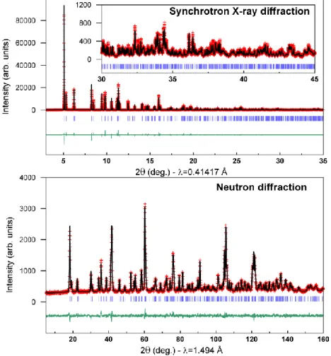
as evidenced by synchrotron XRD and neutron diffraction which will be described below (Figure II.2 and Figure II.3 c). Our exploration on the synthesis of β-Li2IrO3
therefore indicates a strong dependence on the particle size in addition to the temperature: the β phase being easily obtained for particle sizes above a few microns.
II-2-b Structural characterization
The synchrotron X-ray diffraction pattern collected at the MSDP beamline at Alba Synchrotron, Spain, using a wavelength of 0.414 Å was refined using the Rietveld method (Figure II.2), confirming the previously reported Fddd hyperhoneycomb structure (Table II.1)84 with lattice parameters a = 5.905856(8) Å, b = 8.450657(11) Å,
c = 17.81199(2) Å. Due to the large atomic number of Iridium and therefore its
overwhelming contribution to the structure factor, the precision on the positions of Li and O is questionable. NPD, far more sensitive than X-rays to Li and oxygen (bIr=10.6
fm bLi=-1.9 fm bO=5.80 fm) was carried out and the atomic positions are consistent with
the previously reported structure.84 The combined Rietveld refinement of both SXRD and NPD patterns is shown in Figure II.2 and the crystallographic data with atomic positions are listed in Table II.1
Table II.1 Crystallographic data and atomic positions of the β-Li2IrO3 determined from Rietveld refinement of its neutron diffraction pattern. A bond valence sum analysis (BVS) (using d0 from Ir4+) is included.
β-Li2IrO3 Space group F d d d NPD : a = 5.91025(6) Å, b = 8.45727(8) Å, c = 17.81218(16) Å, V = 890.334(14) Å3, R Bragg = 3.45 %, χ2 = 2.31 SXRD : a = 5.905856(8) Å, b = 8.450657(11) Å, c = 17.81199(2) Å, V = 890.353(14) Å3, R Bragg = 5.76 %, χ2 = 7.82
Atom Wyckoff position x/a y/b z/c B (Å2) Occ. BVS
Ir 16g 1/8 1/8 0.70821(14) 0.82(2) 1 3.919(12) Li1 16g 1/8 1/8 0.0489(7) 1.54(16) 1 0.950(7) Li2 16g 1/8 1/8 0.8738(8) 1.40(13) 1 0.999(10) O1 16e 0.8596(8) 1/8 1/8 0.86(4) 1 2.034(10) O2 32h 0.6325(9) 0.36479(17) 0.03830(12) 0.88(2) 1 1.917(10)
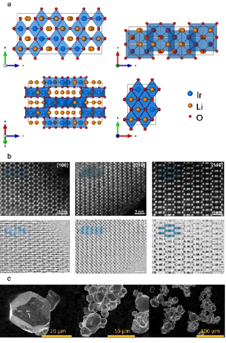
In order to further confirm the structure scanning transmission microscopy (STEM) in both high angle annular dark field (HAADF) and annular bright field (ABF) modes have been carried out and the images are shown in Figure II.3 b. These measurements were performed by Dmitry Batuk under the supervision of Artem Abakumov at the University of Antwerp, Belgium. While the HAADF signal, proportional to the atomic number squared, nicely shows the Ir columns, the ABF images clearly display the O and even Li columns in addition to Ir as certain zone axes
are perpendicular to pure atomic columns of each element. These images confirm the structure obtained by SXRD and NPD pattern refinements.
Figure II.2 Rietveld refinement of the Synchrotron X-ray and neutron powder diffraction patterns for β-Li2IrO3. In red are the experimental points, in black is the calculated pattern and in green is the difference between the experimental and calculated patterns. The vertical blue ticks beneath the pattern indicate the positions of the Bragg reflections. The data could be fitted in an F-centered orthorhombic cell with lattice parameters a = 5.905856(8) Å, b = 8.450657(11) Å, c = 17.81199(2) Å.
Figure II.3 (a) Structure projections of -Li2IrO3 along the main crystallographic zone axes. Note that the [100] and [110] zone axes provide a clear view of the atomic structure with a separation of the atomic species into individual atomic columns. (b) High angular annular dark field scanning transmition microscopy (HAADF-STEM) and Annular Bright Field (ABF) STEM images of the pristine β-Li2IrO3 in the [100], [010] and [110] zone axis. (c) Scanning Electron Microscopy images of β-Li2IrO3 after the two step synthesis route.
The structure of the pristine β-Li2IrO3 being characterized, its electrochemical
II-3 Electrochemical performances
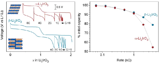
Figure II.4 a) shows the electrochemical behavior of β-Li2IrO3 cycled versus Li
in Swagelok cells between 2 and 4.8 V at a C/10 rate. Remarkably, all Li+ can be removed leading to an “IrO3” phase which can then uptake nearly 1.8 Li in the following
discharge. More specifically, the first charge shows a staircase profile, with the presence of four successive plateaus at 3.45, 3.50, 4.40 and 4.55 V vs Li+/Li0, which can be visualized by four peaks in the dQ/dV plots (Figure II.4 b). Such peaks remain well-defined on the subsequent discharge. This contrasts with the typical behavior of Li-rich oxides: a staircase voltage profile on the first charge that converts to an S-shaped profile on the following discharge which is associated with inter/intra layer cationic migrations.45,87 It also differs from the electrochemical behavior of the α-Li2IrO3
polymorph which shows only two oxidation plateaus that progressively transform upon cycling into S-shaped profiles.50 Figure II.4 b) also shows a weak down shift in voltage of the anodic and cathodic peaks with continued cycling up to 4.8 V which can be avoided by limiting the cutoff voltage to 4.5V. In order to better understand the origin of this voltage decay over cycling, cells cycled over different voltage windows were cycled and the results are described in the following paragraph.
Figure II.4 Electrochemical behavior for β_Li
xIrO3.(a) The voltage profiles for cycles 1 (blue) to ten (orange) with (b) the corresponding derivative plots dQ/dV.
Voltage profiles and the corresponding derivative plots for the 1st and 10th cycles of various cells cycled from 2.0 V to either 4.0 V, 4.5 V or 4.8 V which we will refer to as cell A, B and C respectively, are shown in Figure II.5. While no shift in the voltage