Publisher’s version / Version de l'éditeur:
Vous avez des questions? Nous pouvons vous aider. Pour communiquer directement avec un auteur, consultez la première page de la revue dans laquelle son article a été publié afin de trouver ses coordonnées. Si vous n’arrivez pas à les repérer, communiquez avec nous à [email protected].
Questions? Contact the NRC Publications Archive team at
[email protected]. If you wish to email the authors directly, please see the first page of the publication for their contact information.
https://publications-cnrc.canada.ca/fra/droits
L’accès à ce site Web et l’utilisation de son contenu sont assujettis aux conditions présentées dans le site
LISEZ CES CONDITIONS ATTENTIVEMENT AVANT D’UTILISER CE SITE WEB.
Proceedings of the 5th International Offshore Mechanics and Arctic Engineering
Symposium, 4, pp. 53-57, 1986
READ THESE TERMS AND CONDITIONS CAREFULLY BEFORE USING THIS WEBSITE. https://nrc-publications.canada.ca/eng/copyright
NRC Publications Archive Record / Notice des Archives des publications du CNRC :
https://nrc-publications.canada.ca/eng/view/object/?id=c72488dd-12e9-445a-8f7d-7a4eed7b72cf
https://publications-cnrc.canada.ca/fra/voir/objet/?id=c72488dd-12e9-445a-8f7d-7a4eed7b72cf
NRC Publications Archive
Archives des publications du CNRC
This publication could be one of several versions: author’s original, accepted manuscript or the publisher’s version. / La version de cette publication peut être l’une des suivantes : la version prépublication de l’auteur, la version acceptée du manuscrit ou la version de l’éditeur.
Access and use of this website and the material on it are subject to the Terms and Conditions set forth at
Performance of a frost heave cell for low-temperature-gradient
experiments
Ser
TH1
N21d
National Research
Conseil national
no.
1440
I$
c
ouncil Canada
de recherches Canada
@ *
2
BLDG
Institute for
lnstitut de
- - -
Research in
recherche en
Construction
construction
-
,.
Performance of a Frost Heave Cell for
Low-Temperature-Gradient Experiments
L
by O.J. Svec
Reprinted from
Proceedings of the Fifth (1986) International Offshore
Mechanics and Arctic Engineering Symposium
Tokyo, Japan. 13- 17 April, 1986
Vol. IV, p. 53-57
(IRC Paper No. 1440)
Price $2.00
NRCC 2741 1
NRC-
C1S71I R C
L I B R A R Y
NAY
S
1967
IBIBLIOTHEQUE
II
CNRCI R C
-
IClSTLa r e c h e r c h e e x p g r i m e n t a l e s ' e s t t o u j o u r s vue l i m i t g e p a r l e
b e s o i n d ' u t i l i s e r d e c o u r t s 6 c h a n t i l l o n s d e s o l pour r g a l i s e r
d e s f l u x t h e r m i q u e s u n i d i m e n s i o n n e l s .
Le
p r o f i l d e t e m p 6 r a t u r e
e s t a l o r s c a r a c t g r i s g p a r un f o r t g r a d i e n t
e t l a f r a n g e d e g e l
du s o l e s t t r 2 s 6 t r o i t e .
C e t t e f r a n g e , une bande d e s o l
p a r t i e l l e m e n t g e l g e , e s t l a zone d ' 6 t u d e
l a p l u s i m p o r t a n t e c a r
c ' e s t
l a
que s o n t c r 6 6 s l e s p o t e n t i e l s d ' a s p i r a t i o n c a u s a n t l e
soul8vement p a r l e g e l .
Le
p r g s e n t document t r a i t e d e
l a
c o n c e p t i o n e t d e
l a
mise
3
l ' e s s a i d'un a p p a r e i l e x p g r i m e n t a l
p e r m e t t a n t d ' o b t e n i r un f a i b l e g r a d i e n t thermique e t , p a r
consgquent, une f r a n g e de g e l p l u s 6tendue.
PERFORMANCE OF A FROST HEAVE CELL FOR LOW-TEMPERATURE-GRADIENT EXPERIMENTS
O.J. Svec Div~sion of Building Research National Research Council Canada
Ottawa, Ontario. Canada
ABSTRACT
One limitation of frost heave experimental research has been the necessity to use short soil samples to achieve onedimensional heat flow. The temperature profile is then characterized by a high gradient and the soil has a very narrow freezing fringe. This fringe, a partly frozen band of soil, is the most important region to consider, since it is in this zone that suction potentials are
developed, causing frost heave. This paper reports the design and testing of an experimental apparatus that permits a low thermal gradient and thereby an enlarged freezing fringe.
INTRODUCTION
The consequences of ice segregation and frost heaving in soils have been well-known for centuries. The lifting of footings, cracking of structures, destruction of highways and many other problems associated with differential heave are common in cold climates. Since the total cost of frost heave damages is enormous, understanding the basic mechanism of soil frost heaving is very important indeed.
This problem was documented as early as 1929 by Taber (11, and a few years later by Beskow (2).
Excellent reviews of frost heave research can be found in state-of-the-art papers, for example, Refs. 3-5. Even the first experiments demonstrated that frost heave is not only caused by freezing of in-situ pore water, but also to a much greater extent by the freezing of water moving into the r
freezing zone. The latter process is known as ice segregation or ice lensing. The water flow associated with ice segregation is induced by suction pressures developed in the "freezing fringe"
-
a zone of partly frozen soil behind the freezing front. In spite of considerable effort on the part of many researchers, neither a practical theory tior a full understanding of the basic physics of frost heave is at hand.Frost heave phenomena depend on many factors, such as type of soil (which includes grain,siLe and shape), grain packing, density, moisture content, water availability, thermal conductivity, hydraulic conductivity (i.e., permeability), overburden pressure, and heat extraction. Besides the
overburden pressure, which can greatly influence the rate of heave, the heat extraction rate and
hydraulic conductivity are probably the most important factors in the development of suction potentials, causing water migration and ice segregation. The rate of heat extraction is determined by the product of the temperature gradient in the soil and the effective soil thermal conductivity. The larger the rate of heat
extraction, the smaller the zone between the zero degree isotherm and any actively growing ice lens (i.e., the smaller the freezing fringe).
Hydraulic conductivity is closely related to the rate of heat extraction and to suction
potentials through the adsorbed layers of water on soil particles. Hydraulic conductivity may vary in the freezing fringe by several orders of magnitude. This very large change in its value is accompanied by a large variation in pore water pressure, leading to significant suction potentials.
For the understanding of frost heave phenomena it is imperative to investigate the thermodynamic processes in the freezing fringe. It is very desirable therefore to make this active fringe as large as possible in the laboratory, in order to make a detailed investigation of ice segregation processes. Most scientists involved in frost heave research have used a type of apparatus which achieves a one-dimensional heat flow for only very short samples (100 mm). Consequently, the
temperature gradient in these frost heave cells is generally very high, resulting in a narrow freezing fringe. In terms of engineering applications or frost heave occurring naturally, such temperature gradients are unrealistic.
The purpose of this paper is to report the design of a novel type of frost heaving cell, which
allows the use of long soil samples (300 mm) and low temperature gradients.
DESIGN
The main requirement in designing the long A I R P ~ S S U R L CHAMB~R
vertical cell was to achieve a one-dimensional heat O-RING SHAFI SEAL flow through the soil column (i.e., to minimize
horizontal heat flow through the cell walls). The second objective was to have a cell with a
rectangular cross section so that, in the use of an X-ray imaging technique, the X-rays would travel through an appropriately uniform thickness of soil. Other considerations were to improve the technique for measuring soil temperatures as well as to improve control of the warm end, cold end and external heat exchangers.
One-dimensional Heat Flow
Two assumptions were made for the design of the cell. The first assumption was that it is
sufficient to eliminate horizontal heat flow only in the region of the zero degree isotherm (i.e., within the freezing fringe). In other words, it was asscmed that in an unfrozen or an already frozen part of the soil sample, slight horizontal heat flow would not influence the ice segregation in the
freezing fringe. The second assumption was that by HEAT EXCHANGER
thermally controlling the soil and the cell walls HEAT EXCHANGER CAP
separately, zero temperature difference across the HEAT EXCHANCER n
wall thickness could be achieved
-
at least in a small region-
at any given level of the cell. This assumption was analyzed by a finite element heattransfer model and proved to be realistic. 3 mm STYROFOAM
This line of reasoning led to the design of a INSULATION
single heat exchanger at the top (warm end) and a
double heat exchange system at the bottom (cold end) Fig. 1 A new frost heave cell (w
-
water, of the apparatus (Fig. 1). The lower system m-
methyl alcohol)consists of an internal heat exchanger (I)
controlling the soil sample only, surrounded by an The cell was designed in the form of two external heat exchanger (11) controlling the walls channel sections bolted together to form an internal of the cell. Between these two heat exchangers 3 mm rectangular cross section (75 x 125 mm). In order of styrofoam insulation was placed to minimize to minimize friction between the soil and the cell possible thermal interaction. Thirty thermistors walls, teflon lining has been used. A secondary were embedded in the inside and fifteen fixed on the advantage of the design is that it is possible to outside surface of the cell wall in order to measure split the cell in half and to directly examine the the soil and the cell wall temperatures. These ice segregated soil sample.
temperatures are used to continuously adjust the
temperature of the external heat exchanger. The Soil Temperature Measurements
temperature of the inside soil heat exchanger is For measuring soil column temperatures in frost usually predetermined by the requirements of the heave cells, a common practice has been to place experiment. The external heat exchanger, controlled thermistors behind the teflon lining of the cell, to by a computer, is adjusted so that the inside and protect the thermistors against moisture.
outside cell wall temperatures match at Thermocouples are more easily protected from the approximately the level of the zero degree (Celsius) effects of moisture but are not accurate enough for isotherm. The horizontal heat flow, therefore, is frost heave studies. If glass coated thermistors kept to a minimum at the freezing fringe level. were used, moisture should no longer be a problem;
unfortunately, glass does not adhere completely to Rectangular Cell Shape the wire leads and is very easily damaged. This is
An X-ray imaging technique has been utilized to shown in the photographs of a new thermistor observe the development of ice lenses (6). Most (Fig. 2), taken through an electron microscope. frost heave cells are cylindrical in cross section; Thermistors placed in grooves of the cell wall consequently, in the process of obtaining an X-ray behind the teflon liner do not make direct contact image across the width of the cell, the X-rays pass with the soil. The measured temperature is through soil varying in thickness from zero at the affected, therefore, by the cell wall. To improve walls to a maximum in the centre. The resulting this technique a hole was made in the teflon liner image varies considerably in density, is distorted at the location of every thermistor head.
in its representation of the lens pattern and is Thermistor heads were also insulated from the cell very difficult to interpret except in the central wall by small strips of styrofoam. The rest of the portion. It was reasoned that a rectangular cross space was then filled with a high conductivity section would greatly enhance the X-ray images. epoxy, which was in direct contact with the soil.
soil, as well as 15 thermistors on the outside of
the cell wall
-
are involved in this control system.The main difficulty is to cope with the delay between the time of sensing the need for temperature change at the required level and the time when the temperature of the heat exchanger is actually changed. The proportional setting for this control requires extensive calibration and operating experience.
Consolidation
The cell is designed to permit consolidation of a specimen prior to freezing. There is a porous plate connected to a water supply at the top and
bottom of the sample (Fig. 1). If a sample is
prepared by consolidation in the cell, a soil column of about 200 mm will be achieved. If the sample is
previously consolidated, a 300 mm soil column can
be accommodated. RESULTS OF FINAL TESTS
The test soil was prepared as an artificial
mixture of 75% silt and 25% clay. Samples were
first consolidated under 5 kg/cm2 pressure and then allowed to rebound under no load. No load was applied during tests reported below. The final height of the soil column before a test was about 200 mm. The first test was done with the cell surroundings at normal room temperature. The purpose of this test was to check the cell
operation. The top end of the soil column was not thermally controlled during this test. At the time of taking the X-ray picture (Fig. 3) the vertical heat flow through the soil was 34.6 w/m2 and the horizontal heat flow through the cell walls was 6.0 w/m2. These were very high, due to obviously extreme thermal boundary conditions. Because of the high temperature gradients, the ice lenses were very
sharp, as would be expected (Fig. 3). They are more
or less flat and horizontal, except at the wall, where a definite curvature can be seen. This test indicated that the operation of the entire apparatus was acceptable. For the second test the same type Fig. 2 Brand new thermistor head under electron
microscope
Thermistors used in this study were calibrated individually, resulting in an overall accuracy
(including the data acquisition system) of 20.005°C.
Temperature Controls
The assembled apparatus was kept in a - -
temperature chamber during frost heave tests. The thermal stability of this chamber is about f.0.08°C and it is independently controlled.
As already described, there are three heat exchangers in the frost heave cell. All three are made in the form of plates with a number of serpentine channels. Glycol solution, thermally conditioned by three separate baths, is circulated through these channels. The temperature control for the baths is provided through a Hewlett Packard 1000
computer. Any desired change of temperature for the
cold and warm ends of the soil sample can be programmed.
The temperature of the bath which feeds the heat exchangers of the cell walls is controlled through a special module of the computer program
of soil was consolidated in the cell as described above and the cell was placed in a temperature chamber kept at O.l°C. For this test temperatures of the cold and warm ends were set arbitrarily and were varied as experience was gained with the cell. Emphasis was placed on growing ice lenses while limiting the horizontal heat flow. This test was intended to verify the basic assumptions of the cell design.
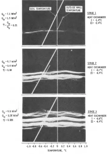
Figure 4 shows three stages of the ice
segregation process. The X-ray images were compared to temperature profiles measured in the soil and partial temperature profiles of the external cell surface. During stage 1, the soil and the outside cell temperatures were not yet fully controlled. The horizontal to vertical heat flow ratio in the freezing zone
(n)
was 0.21. The ice lens was not well defined at the cell sides, while its shape was also slightly convex. The temperature of the ice lens on the freezing fringe side was about -0.2OC.The second stage, when the control of the thermal gradient through the cell walls began, shows considerable improvement. The heat flow ratio
(n)
decreased to 0.04, the shape of ice lenses became flatter (particularly close to the walls), and the lens definition also improved. Ice lenses still had a slightly convex shape but next to the wall they became almost completely horizontal. At this stage
the water supply was stopped for 12 hours, resulting in a retardation of ice growth and a colder
temperature of the ice lens (-0.4OC).
The third stage shows the continuation of the growth phase of stage 2. The water supply was restored, which resulted in an increase in the temperature of the growing ice lens. The heat flow ratio
(s)
decreased again and its value reached 0.028. This means that the vertical heat flow in the soil was more than 30 times higher than the horizontal heat flow through the cell walls. INTERPRETATION OF X-RAY SEQUENCEThe X-ray technique, as part of the overall analysis of the frost heaving process, has been used mainly to establish the position of the growing ice lens and thereby to determine its temperature more accurately. An Optronics drum scanner was used to digitize the density of the X-ray images presented in Figure 4. Using the data from the digitized X-ray picture, density levels were plotted along a line passing through the images of the thermistors in the cell wall. Three density curves,
representing the three stages of the frost heave experiment, were correrated by matching the peaks corresponding to the two thermistors (Fig. 5).
EXTERNAL THERMISTORS NO. 1
,,MJ!?+
F R O Z E N I C E H S E S UNFROZEN
Fig. 5 Digitized density scan of X-ray images
-
plot through a single lineLarge ice lenses, seen as white stripes in Figure 4, are shown in Figure 5 as a decrease in the density to zero. There are many smaller ice lenses spread throughout the frozen part of the sample in front of the first solid ice lens. On the density curve they can be seen as smaller dips. The density
Q,-P.B wld
-
STAGE 3 curve in the unfrozen part of the soil sample showsoH
A hfg wlm2 HEAT EXCHANGERsome "noise" caused by inhomogeneity of the sample.
? = a m I
-
-0.8"~ By comparing the density curve corresponding to theII
-
-8.9"C frozen and unfrozen parts of the sample, a small ice lens can be clearly distinguished from the "density"noise. These smaller ice lenses in the frozen part of the sample, represented by dips in the density curve, can be followed through all three stages of
.
.
, , , 1 ice segregation (as, for example, points 1, 2, 3, 4-1.0 -0.8 -0.6 -aa -0.2 o ar 0.4 0.6 a s 1.0 and 5). The density curve also has a very small
TEMPERATURE. 'C slope. This slight inclination is definitely an
artifact, particularly in the unfrozen part of the soil column. The X-ray is a point source positioned Fig. 4 X-ray sequence of ice segregation
-
chamber at the level of the growing ice lens. Points on thedistorted because X-rays have to penetrate a longer distance through the soil, compared to the path of a ray which is perpendicular to the soil sample. The density curves in the frozen part of the sample are almost identical throughout the freezing process; that strongly indicates that moisture movement in the already frozen soil is extremely small. The time duration for this test was six weeks, so if such a process exists, it must be very slow and may be insignificant for any engineering consideration. The slope of the density curve in the frozen zone is opposite to that expected, due to the point source X-ray. This anomaly is due to the amount of ice in the soil increasing toward the ice lens.
CONCLUSION
A frost heave cell for long soil samples has been designed, constructed and tested. The following conclusions can be drawn based on the first tests.
1. A low temperature gradient was achieved in the freezing zone.
2. Horizontal heat flow was minimized.
3. The rectangular shape of the cell permitted better X-ray definition of the ice lenses. No particular problems were encountered as a result of the cell shape.
4. The computer control of the three heat exchangers was able to achieve and maintain nearly one-dimensional heat flow in the vicinity of the freezing fringe. It is anticipated that predetermined programs of frost heave can be automatically followed.
5. Density scanning of the X-ray images is an asset to analysis and mathematical modelling of the frost heave process and could be improved further by the use of a collimated X-ray technique.
ACKNOWLEDGEMENT
The author is grateful to D. Eldred for his technical assistance. Many thanks are also due to Mrs. C. Merrit of the Electrical Division of the National Research Council Canada for scanning the X-ray images. This paper is a contribution of the Division of Building Research, National Research Council Canada.
REFERENCES
1. Taber S., "Frost heaving", Journal of Geology, Vol. 37, No. 1, pp. 428-461, 1929.
2. Beskow, G., "Soil freezing and frost heaving with special attention to roads and railroads", Swedish Geological Soctety Series C, 375, 26th Year Book, 1935.
3. Loch. J.P.G., "Frost action in soils", State-of-the-art, Proceedings of the Second International Symposium on Ground Freezin
,
Trondheim, Norway. Vol. 18. 1980, pp. 2135224. 4. OfNeill, K.,he
physics bf mathematical frostheave models: a review", Cold Regiona,Science and Technology, Vol. 6, 1983, pp. 275-291. 5. National Research Council. "Ice Senreeation and
6. Penner, E. and Goodrich, L.E., "Location of segregated ice in frost-susceptible soil", Engineering Geology, Vol. 18, 1981, pp. 231-244.
- .
7. Penner, E., "Aspects of ice lens formation", Proceedings of the Third International Symposium on Ground Freezing, U.S. Army Corps of
Engineers, CRREL, Hanover, NH, 1982, pp. 239-245.