HAL Id: hal-00449498
https://hal.archives-ouvertes.fr/hal-00449498
Submitted on 21 Jan 2010HAL is a multi-disciplinary open access archive for the deposit and dissemination of sci-entific research documents, whether they are pub-lished or not. The documents may come from teaching and research institutions in France or abroad, or from public or private research centers.
L’archive ouverte pluridisciplinaire HAL, est destinée au dépôt et à la diffusion de documents scientifiques de niveau recherche, publiés ou non, émanant des établissements d’enseignement et de recherche français ou étrangers, des laboratoires publics ou privés.
Architecture considerations for 60 GHZ pulse
transceiver front-ends
Michael Kraemer, Aubin Lecointre, Daniela Dragomirescu, Robert Plana
To cite this version:
Michael Kraemer, Aubin Lecointre, Daniela Dragomirescu, Robert Plana. Architecture considerations for 60 GHZ pulse transceiver front-ends. International Semiconducteur Conference, CAS 2007, Oct 2007, Sinaia, Romania. �hal-00449498�
ARCHITECTURE CONSIDERATIONS FOR
60 GHZ PULSE TRANSCEIVER FRONT-ENDS
M. Kraemer*,** , A. Lecointre*,**, D. Dragomirescu*,**, R. Plana*
*LAAS-CNRS, University of Toulouse, France **INSA Toulouse, Toulouse, France
E-mail: [email protected]
Abstract
While Impulse Ultra Wideband (I-UWB) is well estab-lished in the frequency range between 3.1 and 10.6 GHz, the application of pulse modulation in the frequency band around 60 GHz is a recent develop-ment. In this paper, the properties of 60 GHz pulses are outlined. Different architectures for pulse based transceiver front-ends are compared. It is distin-guished between the up-conversion of UWB-pulses and their direct generation at millimeter-wave (mm-wave) frequencies. Both non-coherent and coherent receiver front-ends are considered. These considera-tions form the basis for a future 60 GHz UWB trans-ceiver in 65 nm CMOS SOI that can be employed as part of a System on Chip (SoC) for sensor networks. Keywords: UWB, millimeter-wave, 60 GHz, pulse, coherent
1. INTRODUCTION
The desired properties for wireless sensor networks are manifold [1]: Depending on the application, high data rate, multi-user capability, low probability of detection and/or interception and very low cost and power consumption are demanded. These require-ments can be met by transceivers using pulse based modulation techniques [2]. Time Hopping (TH) Pulse Position Modulation (PPM) is hereby the most prom-ising scheme [3].
Because of its inherently transient nature, pulse modulation needs large bandwidths. One possibility is therefore the use of the UWB frequencies between 3.1 and 10.6 GHz. However, this frequency range is al-ready occupied by other narrowband signals like WLAN, resulting in both a high interference level and a low permitted transmit power. The recent bulletin of the regulatory bodies in Europe constrains the use of parts of this frequency range even more.
Therefore, more and more research interest is fo-cused on the frequency range around 60 GHz. Here, an unoccupied bandwidth of at least 7 GHz is avail-able in the US, Europe and Japan with very high emission limits not likely to be exceeded by fully integrated transceivers. [4], [5].
Other advantages of this frequency range are a po-tentially high user density due to strong signal at-tenuation, small device dimensions permitting a true SoC architecture, a strong line-of-sight path (possible with directive antennas having mm-dimensions) and small delay spread introduced by the channel.
Alto-gether, there is a potential for data-rates between 1 and 10 Gbit/s.
While the mm-wave range was until recently only accessible by expensive III-IV semiconductors, the suitability of SiGe [6], and later CMOS technologies [7],[8],[9] for fully integrated transceiver circuits was demonstrated. The presented transceiver front-ends are intended for up- and down-conversion of modulated baseband signals not further specified.
In the first explicit demonstration of pulse modula-tion at 60 GHz, baseband PPM pulse trains are simply up-converted. A transmitter of that kind was first im-plemented in a III-IV [10] and later in SiGe BiCMOS technology [11]. The employed receivers use non-coherent detection for the down-conversion of the UWB-pulses.
Very recently, pulse generators (PG) that emit true UWB-pulses directly at 60 GHz were demonstrated. The approach in [12] uses CMOS-technology to delay ultra-short pulses and arrange a 60 GHz pulse, while in [13] an injection-locked oscillator is rapidly switched on and off.
The paper at hand will compare the different possi-bilities of pulse modulation techniques at 60 GHz. A conversion approach and a direct approach are explic-itly distinguished. The principle architectures of the appropriate mm-wave front-ends are outlined. While up to date, the published receiver architectures for pulse modulation use non-coherent down-conversion methods, this paper shows the advantages and chal-lenges of a carrier phase or pulse timing recovery.
In chapter 2 the characteristics of pulses at 3.1-10.6 GHz and 60 GHz are compared. In chapter 3 transmitter architectures for both approaches are pre-sented. In chapter 4 the receiver principles are out-lined. Chapter 5 gives some simulation results that compare coherent, correlation and non-coherent mm-wave front-ends.
Based on the simulation results and discussions in this paper, an architecture can be selected to build a PPM-TH-receiver in 65 nm CMOS SOI with superior performance.
2. PULSE WAVEFORMS
A simple PPM signal consisting of pulses with the constant pulse shape g(t) can be described mathemati-cally as [3]
with a pulse rate of 1/Td, a time delay between two
adjacent pulse positions of δ, and the symbol to be transmitted at a discrete time instant k to be dk. For
sake of simplicity, TH is not included in (1).
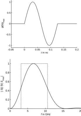
In the 3.1 to 10.6 GHz band, a monocycle is a typi-cal, simple pulse waveform g(t) approximately meet-ing the spectrum requirements. Its representation in the time and frequency domain is given in figure 1. Note that due to its large relative bandwith brel > 100%
its characteristics are ultra-wideband with no oscilla-tions occurring.
The pulse waveforms required for the 7 GHz range available at 60 GHz must look differently: because the relative bandwidth available is only brel = 11.7 %, a
classical UWB waveform is not suited. The required waveform has narrowband, oscillating behaviour. A modulated Gaussian pulse meets these requirements. An example for such a pulse is depicted in Figure 2.
Note the difference in mathematical representation between up-converted pulses and pulses directly gen-erated at mm-waves: In the former case, the constant pulse waveform that is position-modulated is
e , (2)
while in the latter the shifted pulse waveform is
e cos 2 . (3)
This implies that for PPM with true 60 GHz-pulses like g2(t) the sinusoid is shifted with the pulse position
according to (1). This causes fundamental differences of the architectures of both transmitter and coherent receiver front-end between the conversion approach and the direct approach.
3. TRANSMITTER
ARCHITECTURES
In this chapter, the two principle architectures for pulse transmitters are compared. It is always distin-guished between the conversion approach, where baseband pulses like the one given in (2) are up-converted, and the direct approach, where pulses ac-cording to (3) are generated and transmitted directly at 60 GHz.
3.1. CONVERSION APPROACH
The block diagram of a transmitter using the conver-sion approach is sketched in Figure 3. The input signal of this transmitter is a PPM pulse train in the baseband with already shaped pulses g1(t). Alternatively,
super-heterodyne-structures with one or more intermediate frequencies are possible, as well as lower oscillator frequencies that are multiplied to yield 60 GHz.
A modified version of this architecture is realized in [10] and [11]. There, the up-conversion is done by a switch instead of the mixer, necessitating a filter to shape the pulse at 60 GHz.
Figure 3: Millimeter-wave front-end for conversion approach
PA
60 GHz
IN
Figure 1: 3-10 GHz Monocycle and its normalized power density spectrum
-0.05 0 0.05 0.1 0.15 0.2 -1 -0.5 0 0.5 1 t in ns g (t) /gma x 0 5 10 15 20 0 0.2 0.4 0.6 0.8 1 f in GHz | S |( f )/ | S ma x | -0.2 -0.1 0 0.1 0.2 0.3 -1 -0.5 0 0.5 1 t in ns g ( t )/ g ma x
Figure 2: Gaussian-shaped 7 GHz- pulse g(t) at 60 GHz
3.2 DIRECT APPROACH
At the direct approach the pulses are generated by a mm-wave pulse generator (PG), like the ones pre-sented in [13], [14]. The input hereby is a digital pilot signal that designates the time instants when a pulse needs to be launched. The unifying property of all mm-wave PGs of this type is that the phase of the sinusoidal part of (3) always remains constant with respect to the maximum of the pulse. The transmitter principle for the direct approach is illustrated in fig-ure 4.
Figure 4: 60 GHz pulse transmitter
4. RECEIVER ACHITECTURES
In this chapter receiver front-ends that facilitate the detection of the pulse positions in the baseband are shown. While the non-coherent down-conversion receiver works together with both transmitters, in chapter 4.2 and 4.3 receivers that are matched to the transmitter type are introduced.
4.1. NON-COHERENT APPROACH
In figure 5 the non-coherent receiver front-end is shown. The output-signal of this receiver yields the (noise-corrupted) envelope of the sent pulse train. If a additive white Gaussian noise (AWGN) channel with noise contribution n(t) that corrupts the sent 60 GHz pulse g2(t) is assumed, the output signal (in front of
the low-pass filter) is
2 . (4)
This signal contains a squared noise component. The same holds if the input signal originates from a conversion-approach transmitter, because no synchro-nization with the 60 GHz carrier phase is achieved.
The following two chapters propose architectures that synchronize either the carrier phase or the posi-tion of the 60 GHz pulses in order to reduce the noise contribution.
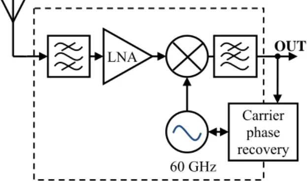
4.2 CONVERSION APPROACH The block diagram of a coherent receiver front-end for up-converted UWB-pulses is given in Figure 6. If carrier phase recovery can be accomplished, this cir-cuit completely reconstructs the sent pulse train. Be-cause the received signal, that is assumed to be only corrupted by the additive noise term n(t), is multiplied with a uncorrupted, recovered carrier, the down-converted signal only contains a linear noise contribu-tion:
cos 2 cos 2 (5) The carrier phase recovery circuit that eliminates the phase difference φ can be accomplished by using feedback loops. A first PLL circuit at 60 GHz is dem-onstrated in [14] in BiCMOS SiGe technology.
Note that in contrast to the direct approach that will be presented in the following chapter, the down-converted baseband signal still needs to be analogly processed, i.e. by matched filtering.
4.3 DIRECT APPROACH
The principal receiver structure for the direct ap-proach is depicted in figure 7. The received 60 GHz pulses are not down-converted, but directly correlated with template pulses launched by a PG according to
d (7)
with T0 being the duration of one pulse.
The challenge of this approach is to recover the pulse timing in order to determine when the template pulses need to be emitted: This will be accomplished for t0=0 in (7). Different from the carrier phase
recov-ery, where synchronization is done on one of the pe-riodically occurring maxima of the auto-correlation function (ACF), the pulse timing recovery needs to detect the global maximum of the ACF. An example for an ACF of a 60 GHz pulse is depicted in figure 8 to illustrate the problem. A solution for this task was not
Figure 6: Coherent receiver front-end for up-converted UWB pulses
LNA 60 GHz OUT Carrier phase recovery PA IN 60 GHz PG OUT LNA
yet show receiver i ly decide F In orde sented re versus in lated in M two idea Figure 9 SNR is a proaches Two d direct ap discussed conversio synchron superior p for pulse For a f one of th dependin -1 -0.5 0 0.5 1 ρ( t 0 - t 1 )/ ρ max wn. Note that t is already mat d on. Figure 8 : Nor G
5. SIMUL
er to compar eceiver princip nput Signal-to Matlab for a ally synchron show the be about 5 dB l when achievi6. CO
different trans pproach and d. In additio on of the recei nization were performance based modula future 65 nm he proposed ng on importa -0.2 -0 0 5 Figure direct dem LNthe output sig tched-filtered
rmalized ACF aussian pulse
LATION RE
re the perform ples, the Bit
-Noise Ratio non-coherent nized receiver enefits of syn ower for the ing the same B
ONCLUSIO
sceiver archite a conversion n to a non-ived pulses, pu suggested. Si of these adva ations at 60 G m CMOS SOI architectures ant properties 0.1 0 0 t 0- t1 in ns 7: Correlation modulation of NAgnal of this typ and can be di F of a 60 GHz e
ESULTS
mance of the Error Rate (B (SNR) was s t receiver and rs. The resul nchronisation: synchronized BER.ONS
ectures, name n approach, -conherent d ulse receivers imulations sh anced architec GHz. UWB transc will be sele s of these cir 0.1 0.2 0 n receiver for f 60 GHz pulse pu tim reco∫
0 0 d T t pe of irect- pre-BER) simu-d the lts in The d ap-ely a were with ow a ctures ceiver ected, rcuits like requi d [1] L Wirel Confe [2] W Comm [3] I. and A [4] N dio: Journ [5] S wirele IEEE [6] R ”60G ISSCC [7] D Journ [8] R IEEE [9] A GHz in 90 grated [10] wide data r 34th E [11] M systèm JNM [12] B gener [13] D la sy d’imp [14] W F.: “A applic .3 -es OUT ulse ming overy power consum irements and c Figure 9: BE detection and s Lecointre, A.; less Sensor N erence, 2006, pWin, M. & Scho
munications Let Oppermann, M Applications“, J N. Guo, R.C. Q Principle, Tec nal on Wireless Smulders, P.: “ ess multimedia E Communicatio Reynolds, S.; GHz transceiver C 2004, Digest Doan, C et al.: “ nal of Solid-Stat Razavi, B.: “A E Journal of Sol Alldred, D.; Cou radio receiver 0-nm CMOS”, d Circuit Symp Deparis, N et band width im rates multiple European Micr M. Devulder et me Ultra Large 2007 Badalawa, B. & rator”, IEEE Ele Deparis, N. et a ynchronisation pulsions ULB e Winkler, W.; B A fully integrat cations”, ISSCC 15 -5 sy mption, size, cost. ER versus SN synchronous d REFEREN Dragomirescu, Networks”, Inte . 13-17 oltz, R.: “Impu tters, IEEE, 199 M. Hämäläinen, John Wiley & S Qiu et al.:”60-G chnology and Communicatio “Exploiting the access: prospe ons Magazine, 2 Floyd, B.; Pf r circuits in S of Technical P “Millimeter-wa te Circuits, 200 A 60-GHz CM id-State Circuit
usins, B. & Voi with on-chip tr IEEE Compo osium, 2006, p. al.:”Transposit mpulse radio si access indoor rowave Confere t al.:” Conceptio e Bande en tech & Fujishima, M ectronics Letter
al.: “Module rad d’une source en bande de bas Borngraber, J.; ted BiCMOS P C 2005, p. 406-4 5 SNR (dB)5 ynchronized realizability, NR for non-coh demodulation, NCES D. et al: “M ernational Sem
ulse radio: how 98, p. 36-38
J. Iinatti:“UWB Sons, Chichester GHz Millimeter
New results”,
ons and Network
e 60 GHz band ects and future d 2002, p.140-147 feiffer, U. & Z iGe bipolar te
Papers. p. 442-5
ave CMOS des
05, p.144-155 MOS receiver ts, 2007, p. 17-2 inigescu, S.: “A ransformers and und Semicond . 51-54 tion of a base ignal at 60 GH communication ence, 2004,p. 10 on de circuits 6 hnologie BiCM M.: “60 GHz CM rs, 2007, p.100-dio millimétriq 30 GHz par e“, JNM 2007 Heinemann, B. PLL for 60 GH 407, Vol.1 1 1 1 1 1 1 15 ) back-end herent , 1Gbit/s Miniaturized miconductor w it works”, B – Theory r, 2004 r-Wave Ra-EURASIP king, 2007 d for local directions”, 7 Zwick, T.: echnology”, 538, Vol.1 ign”, IEEE front-end”, 22 A 1.2V, 60-d in60-ductors ductor Inte-band ultra Hz for high n systems”, 05-108 60 GHz pur MOS SiGe”, MOS pulse -102 que utilisant des trains . & Herzel, Hz wireless 1,0E-05 1,0E-04 1,0E-03 1,0E-02 1,0E-01 1,0E+00 BER