Departement de genie civil
FINITE ELEMENT MODELLING OF EXTERNALLY
SHEAR-STRENGTHENED BEAMS USING FIBRE REINFORCED
POLYMERS
MODELISATION PAR ELEMENTS FINIS DU RENFORCEMENT
EXTERNE EN CISAILLEMENT DES POUTRES EN BETON ARME
EN UTILISANT LES POLYMERES RENFORCES DE FIBRES
These de doctorat es sciences appliquees Speciality genie civil
Jury: Dominique Levebvre Fredric Legeron Kenneth W. Neale Pierre Labossiere Emmanuel Ferrier Omer Chaallal Amir Fam President Rapporteur Directeur de recherche Codirecteur Examinateur Examinateur Examinateur
Sherbrooke (Quebec), CANADA
Ahmed GODAT Juillet 2008
1*1
Library and
Archives Canada
Published Heritage
Branch
395 Wellington Street Ottawa ON K1A0N4 CanadaBibliotheque et
Archives Canada
Direction du
Patrimoine de I'edition
395, rue Wellington Ottawa ON K1A0N4 CanadaYour file Votre reference ISBN: 978-0-494-42676-0 Our file Notre reference ISBN: 978-0-494-42676-0
NOTICE:
The author has granted a
non-exclusive license allowing Library
and Archives Canada to reproduce,
publish, archive, preserve, conserve,
communicate to the public by
telecommunication or on the Internet,
loan, distribute and sell theses
worldwide, for commercial or
non-commercial purposes, in microform,
paper, electronic and/or any other
formats.
AVIS:
L'auteur a accorde une licence non exclusive
permettant a la Bibliotheque et Archives
Canada de reproduire, publier, archiver,
sauvegarder, conserver, transmettre au public
par telecommunication ou par Plntemet, prefer,
distribuer et vendre des theses partout dans
le monde, a des fins commerciales ou autres,
sur support microforme, papier, electronique
et/ou autres formats.
The author retains copyright
ownership and moral rights in
this thesis. Neither the thesis
nor substantial extracts from it
may be printed or otherwise
reproduced without the author's
permission.
L'auteur conserve la propriete du droit d'auteur
et des droits moraux qui protege cette these.
Ni la these ni des extraits substantiels de
celle-ci ne doivent etre imprimes ou autrement
reproduits sans son autorisation.
In compliance with the Canadian
Privacy Act some supporting
forms may have been removed
from this thesis.
Conformement a la loi canadienne
sur la protection de la vie privee,
quelques formulaires secondaires
ont ete enleves de cette these.
While these forms may be included
in the document page count,
their removal does not represent
any loss of content from the
thesis.
Canada
Bien que ces formulaires
aient inclus dans la pagination,
il n'y aura aucun contenu manquant.
Le besoin en rehabilitation des structures en beton est bien connu. Un grand nombre de recherches sont dans ce domaine. L'utilisation de polymeres renforces de fibres dans la rehabilitation a montre que cette solution est competitive du point de vue de sa per-formance structurale et de son aspect economique. Le renforcement au cisaillement des poutres en beton est necessaire quand la poutre est deficiente en cisaillement, ou quand sa capacite au cisaillement devient insufBsante apres de son renforcement en flexion. Une technique qui a fait ses preuves pour le renforcement des poutres en beton est de coller des lamelles de composites additionnelles.
Au cours des dernieres annees, une grande quantite de travaux de recherche a ete con-duite sur le renforcement au cisaillement avec des composites et cela a mene a une meilleure comprehension du comportement. Plusieurs equations de design ont ete proposees pour le calcul de poutres de beton arme renforcees au cisaillement avec des composites. La plupart des parametres qui controlent le comportement des poutres renforcees au cisaillement ont ete identifies. Les equations de design, qui decrivent le comportement des poutres ren-forcees au cisaillement, ne sont pas sufhsantes pour evaluer la contribution au cisaillement des composites PRF utilises. Ceci peut etre attribue a l'absence d'un modele numerique precis, dont l'utilisation est plus economique que l'experimentation, pour tenir compte des complexites du comportement des poutres renforcees au cisaillement et pour atteindre une meilleure comprehension des mecanismes de rupture.
Des analyses limitees par element finis ont ete effectuees sur les poutres renforcees en cisaillement. Comme contribution pour remplir ce manque, un modele numerique versatile est developpe dans cette etude pour predire le comportement des poutres renforcees au cisaillement par des composites, avec une emphase sur le comportement de l'interface et le probleme du delaminage. Cette recherche est divisee en trois parties : (1) le developpement d'un modele numerique capable de capturer le comportement reel des poutres renforcees en cisaillement; (2) le modele numerique propose applique a differents cas de configurations de renforcement, tel que, poutres avec des lamelles verticales ou des lamelles inclinees, des poutres avec des enveloppes en forme de U, ainsi que des poutres avec des lamelles ancrees aux extremites et; (3) une etude parametrique faite pour evaluer l'innuence sur
le comportement au cisaillement du taux d'armature des etriers, de la resistance a la compression du beton, du module elastique du composites, ainsi que son epaisseur, et du rapport entre la largeur du composites et celle de la poutre.
Le modele numerique propose ici est valide avec les resultats experimentaux provenant de la litterature. Les resultats predits concordent bien avec ceux des experimentations. On va montrer que l'element essentiel de 1'analyse par element finis est la modelisation de l'interface composite-beton. L'utilisation des elements d'interface predit de bons resultats du comportement des poutres renforcees en cisaillement. En outre, 1'analyse numerique nous permet d'avoir des informations sur le glissement et la propagation du delaminage du composite le long de l'interface. Des analyses des deformations des les lamelles sont aussi presentees.
Des equations de regression ont ete developpees, sur la base d'une approche statistique (RSM). De nouvelles equations de design ont ete proposees pour les cas de lamelles collees et pour les enveloppes en forme de U. Les equations proposees peuvent etre utilisees dans un guide de conception de la contribution du composites au cisaillement. Quelques resultats de ce travail de recherche peuvent etre trouves dans Godat et al. [2007a,b].
The need for structural rehabilitation of concrete structures all over the world is well known. A great amount of research is going on in this field. The use of fibre reinforced polymer (FRP) plate bonding has been shown to be a competitive solution regarding both the structural performance and the economical aspects. Shear strengthening of reinforced concrete beams is required when the beam is deficient in shear, or when its shear capacity-falls below its flexural capacity after flexural strengthening. An accepted technique for the shear strengthening of reinforced concrete beams is to provide an additional FRP web reinforcement in the form of externally bonded FRP sheets.
Over the last few years, a considerable amount of research has been conducted on shear strengthening with FRP composites and that has led to a better understanding of the be-haviour. Hence, many design equations have been proposed to design shear-strengthened beams. Most of the parameters that control the behaviour of shear-strengthened beams have been addressed. However, the design equations describing the behaviour of shear-strengthened beams are not sufficient to properly evaluate the shear contribution of the FRP composites. This might be attributed to the absence of an accurate numerical model, which is more economical than the experimental tests, to capture the complex-ities of shear-strengthened beams and to lead to a better understanding of the failure mechanisms.
Limited finite element analyses have been carried out on FRP shear-strengthened beams. As a contribution to fill this need, a versatile numerical model is developed in this study to predict the response of reinforced concrete beams strengthened in shear with bonded FRP composites, with a particular emphasis on the interfacial behaviour and debonding phenomena. This research consists of three phases. They are: (1) the development of a reliable numerical model that can capture the real behaviour of FRP shear-strengthened beams; (2) the use of the proposed numerical model to verify various cases having different strengthening configurations: beams with vertical and inclined side-bonded FRP sheets, the U-wrap scheme, as well as anchored FRP sheets and; (3) a parametric study conducted to identify design variables that have the greatest influence on the behaviour of shear-strengthened beams such as the steel stirrup reinforcement ratio,
concrete compressive strength, FRP elastic modulus, FRP thickness, and ratio between FRP width to beam width.
The proposed numerical model is validated against published experimental results. The predicted results are shown to compare very well with test results. It is shown that the formulation of the FRP/concrete interfacial behaviour is essential to analyses utiliz-ing finite element models. The implementation of interface elements produces accurate predictions of the response of shear-strengthened beams. Furthermore, the numerical analysis provides useful information on the slips and propagation of debonding along the FRP/concrete interfaces. Predicted strain profiles along the FRP sheet depth are also presented.
Regression equations based on the statistical approach of the response surface method-ology (RSM) are developed. New design equations to describe the FRP axial effective strain at the state of debonding are proposed for both side-bonded and U-wrap strength-ening schemes. The proposed design equations can be used to provide simple design guidelines to predict the FRP shear contribution. Some of the results of this thesis re-search can be found in Godat et al. [2007a,b].
to my brothers and sisters...
to those gave me their hearts...
and their hearts are always with me...
A c k n o w l e d g e m e n t s
Praise be to Allah Almighty and Peace be upon His Prophet Mohammed.
After thanking God for giving me the opportunity and strength, I would like to express my gratitude to the institutions and people who contributed, one way or another, in making this work come true and helping me reach this station in my academic life. For them I would like to say thank you with all my respect and appreciation.
First, I would like to thank my supervisors Professors Pierre Labossiere and Kenneth Neale. Professor Kenneth Neale is a rich source of information. He taught me that academic work has neither limit, nor boundary. I would like to thank him for being patient, helpful and an ambitious supervisor. He is a tough examiner, yet has a kind personality. I am also deeply thankful to my supervisor, Professor Pierre Labossiere, for his valuable backup and guidance. We had together very fruitful discussions that cleared my mind and lit my thoughts.
With special love I would like to acknowledge the encouragement from my family in Sudan. They have always been there for me, with their endless love and support. I would like to thank all my colleagues at the Civil Engineering Department at the University of Sherbrooke. Special thanks go to my colleagues and friends Hussien Abdel Baky and Walid Elsayed, for their deep discussions, endless support and for making the difficult moments fun and easy. I would like also to thank the Sudanese Society at Montreal for the continuous inspiration during my studies. My special thanks go to my friends Nazar Alameen and Mohammed Askri, for being such wonderful and supporting friends.
This research was funded by the Natural Sciences and Engineering Research Council of Canada (NSERC), and the Canadian Network of Centres of Excellence on Intelligent Sensing for Innovative Structures (ISIS Canada). This support is gratefully acknowledged.
Contents
1 Introduction 1 1.1 General 1 1.2 Scope 4 1.3 Research Objectives 5 1.4 Outline 5 2 Literature Review 7 2.1 Introduction 7 2.2 Techniques for the Shear Strengthening of Beams 72.2.1 Traditional Techniques 8 2.2.2 Fibre Reinforced Polymer Technique 10
2.3 Concept of Shear Strengthening using FRP composites 14
2.4 Shear Behaviour of Reinforced Concrete Beams 15 2.4.1 Shear Behaviour of RC Beams without FRP Strengthening 15
2.4.2 Shear Behaviour of FRP Shear-Strengthened RC Beams 17 2.4.2.1 Shear Failure Controlled by FRP Rupture 17 2.4.2.2 Shear Failure Controlled by FRP Debonding 18
2.5 Parameters Influencing Shear-Strengthened Beams 20
2.5.1 Beam Dimensions 21 2.5.2 Strengthening Schemes 22 2.5.3 FRP Dimensions and Characteristics 24
2.6 Anchorage of the FRP plates 25 2.7 FRP Shear-Strengthened Design Models 30
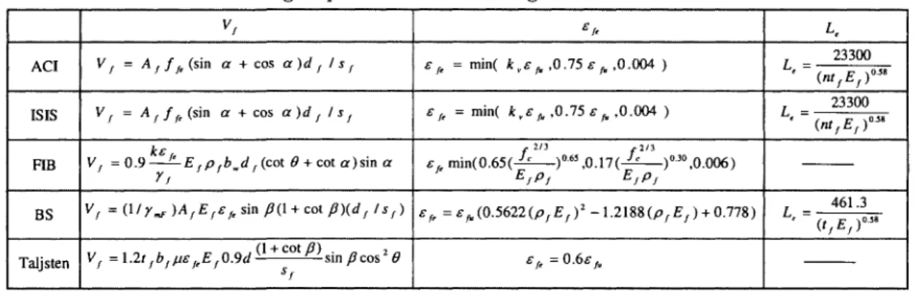
2.7.1 Truss Design Model 31 2.7.1.1 ACI Model 31 2.7.1.2 ISIS Model 33 2.7.1.3 FIB Model 33 2.7.1.4 BS Model 34 2.7.1.5 Taljsten Model 35 2.7.2 Modified Compression Field Theory (MCFT) 36
CONTENTS
2.8 Axial Strain Profile along the FRP Composites 38
2.9 Numerical Modelling 40 2.9.1 Introduction 40 2.9.2 Finite Element Packages 41
2.9.3 Modelling of Concrete 42 2.9.3.1 Concrete in Compression 42
2.9.3.2 Crack Modelling 43 2.9.3.3 Tension Stiffening Model 45
2.9.3.4 Shear Retention Factor 45 2.9.3.5 Convergence of Results 46 2.9.4 Modelling of Bonded FRP Composites 47 2.9.5 Modelling of FRP/Concrete Interfacial Behaviour 48
2.10 Summary 53
3 Development of a Reliable Numerical Model 54
3.1 Introduction 54 3.2 ADINA Finite Element Model 55
3.2.1 Material Modelling 56 3.2.1.1 Concrete 56 3.2.1.2 Steel Reinforcement and FRP Composites 57
3.2.1.3 FRP/Concrete Interface 57
3.2.2 Structural Modelling 59 3.2.2.1 Modelling of FRP Composites 60
3.2.2.2 Modelling of FRP Concrete Interface 60
3.2.3 Horizontal Interface Elements 63 3.2.4 Finite Element Discretization 64 3.3 DIANA Finite Element Model 64
3.3.1 Concrete 65 3.3.2 Steel Reinforcement and FRP Composites 65
3.3.3 FRP/Concrete Interface 66
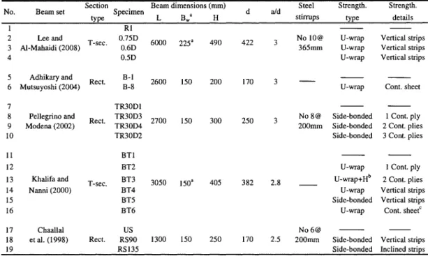
3.4 Specimens Investigated 67 3.4.1 Pellegrino and Modena Specimens 69
3.4.2 Chaallal et al. specimens 70 3.4.3 Adhikary and Mutsuyoshi Specimens 70
3.4.4 Khalifa and Nanni Specimens 72 3.4.5 Lee and Al-Mahaidi Specimens 73
3.5 Summary 73
4 Validation of Numerical Results 77
4.1 Introduction 77 4.2 Comparison Between Shell and Truss Modelling of FRP Composites . . . . 77
4.2.1 Load-Deflection Relationships and Failure Modes 78 4.2.2 Axial Strain Profiles along the FRP Composites 84 4.3 Comparison Between Various Interface Elements 86
4.3.1 Load-Deflection Relationships 86 4.3.2 Slip Profiles along the FRP/Concrete Interface 87
4.3.3 Bond-Slip Model 92 4.4 Influence of Horizontal Interface Elements 94
4.5 Results of Finite Element Discretization 94 4.6 Comparison between DIANA and ADINA Results 97
4.7 Summary 100
5 Size Effects for RC Beams Strengthened with F R P Composites 102
5.1 Introduction 102 5.2 Experimental Program 103
5.3 Numerical Analysis 107 5.4 Experimental and Numerical Results 108
5.4.1 Ultimate Load Carrying Capacities and Failure Modes 108
5.4.2 Load-Deflection Relationships 112
5.4.2.1 First Series 112 5.4.2.2 Second Series 113 5.4.2.3 Third Series 114 5.4.3 Strain Distribution along the FRP Sheet Depth 116
5.4.3.1 First Series 116 5.4.3.2 Second Series 118 5.4.3.3 Third Series 119 5.4.4 Slip Profiles along the FRP/Concrete Interface and Shear Crack
Angles 120 5.4.4.1 First Series 120
5.4.4.2 Second Series 123 5.4.4.3 Third Series 124
5.5 Summary 125
6 Numerical Predictions for Various Configurations of F R P Composites 127
6.1 Introduction 127 6.2 Experimental Program 128
6.3 Numerical Program 132 6.4 Numerical Results and Discussion 134
6.4.1 Ultimate Carrying Capacities 134 6.4.2 Load-Deflection Relationships and Failure Modes 136
6.4.2.1 First Series 136 6.4.2.2 Second Series 137
CONTENTS
6.4.2.3 Third Series 139 6.4.3 Strain Distribution Along the FRP Sheet Depth 140
6.4.4 Slip Profiles along the FRP/Concrete Interface and Shear Crack
Angles 143 6.4.4.1 First Series 144
6.4.4.2 Second Series 145 6.4.4.3 Third Series 148
6.5 Summary 149
7 Parametric Studies and Design Equations 151
7.1 Introduction 151 7.2 Parametric Studies 153
7.2.1 Parameters of Bond-Slip Model 153 7.2.1.1 Effect of Interfacial Stiffness 153 7.2.1.2 Effect of Interfacial Bond Strength 155 7.2.1.3 Effect of Interfacial Fracture Energy 155 7.2.2 Parameters of Shear-Strengthened Beams 158
7.2.2.1 Steel Stirrups 158 7.2.2.2 Concrete Compressive Strength 158
7.2.2.3 Effect of FRP Elastic Modulus 159 7.2.2.4 Effect of FRP Thickness 161 7.2.2.5 Effect of Width Ratio Between the Bonded FRP Plate to
the Concrete Member 161 7.2.2.6 Effect of Shear Span to Depth Ratio 162
7.3 Design Equations 163 7.3.1 Response Surface Methodology (RSM) 165
7.3.2 Monte Carlo Simulation 167 7.3.3 Nonlinear Regression Analysis 168 7.3.4 Proposed Design Equations 168 7.3.5 Comparison with Experimental Results 170
7.4 Prediction of FRP Axial Effective Strain Profile 176
7.5 Summary 178
8 Conclusions and Recommendations 181
8.1 Introduction 181 8.2 Conclusion from Development of a Reliable Numerical Model 183
8.3 Conclusion from Size Effects of RC Beams Strengthened with FRP
Com-posites 184 8.3.1 Experimental Investigations 184
8.3.2 Numerical Investigations 184 8.4 Conclusion from Various Configurations of FRP Composites 185
8.5 Conclusion from Design Equations 186 8.6 Recommendations for Future Work 186
Appendices 199 A A D I N A Concrete Constitutive Model 199
A.l Concrete in Compression 199 A.2 FE Material Failure Envelopes 201 A.3 Fixed Smeared Crack Model 202
LIST OF FIGURES
List of Figures
2.1 Examples of shear-strengthening techniques 8 2.2 Post-tensioning shear-strengthening technique [Deniaud, 2000] 9
2.3 Deficient beam in shear strengthened with steel plates [Barnes et al., 2001] 10
2.4 Concrete jacketing for slabs and beams [Deniaud, 2000] 10 2.5 Examples of F R P strengthening for concrete structures 11
2.6 Concrete bridge shear-strengthened with F R P s 12 2.7 Various schemes for wrapping F R P shear strengthening: (a) complete
wrap-ping, (b) U-wrapwrap-ping, (c) side-bonding 12 2.8 Various F R P shear strengthening distributions: (a) continuous
reinforce-ment, (b) F R P strips 13 2.9 Sheets with their fibres oriented in various primary directions: (a) inclined
sheets, (b) vertical sheets 13 2.10 Beams with bi-axial shear reinforcement: (a) vertical bi-axial sheet, (b)
inclined bi-axial sheets 13 2.11 Beam with vertical NSM F R P rods for shear strengthening Lorenzis and
Nanni [2001] 14 2.12 Variation of shear strength with shear-span/effective depth ratio [Mosallam
and Banerjee, 2007] 16 2.13 Shear rupture failure of the F R P sheets [Carolin and Taljsten, 2005] . . . . 18
2.14 Shear debonding failure of the F R P sheets in: (a) U-wrap [Khalifa and
Nanni, 2000], (b) side-bonded [Pellegrino and Modena, 2002] 19 2.15 Diagram of the shear behaviour of reinforced concrete beams 20 2.16 Diagram of the parameters influencing shear strengthened beams 26 2.17 Mechanical anchorages types of the F R P sheets by Sato et al. [1997b] . . . 28
2.18 Details of the U-anchor by G F R P rod: (a) groove into the flange, (b) groove
into the web [Khalifa and Nanni, 2000] 28 2.19 F R P bonded to the underside of the flange [Deniaud and Cheng, 2001a] . . 29
2.20 Details of the L-shaped anchorage [Lee, 2003] 29 2.21 Axial strain profile along the beam hight [Carolin and Taljsten, 2005] . . . 40
2.22 Axial strain profile the shear crack for: (a) side-bonded beams; (b) U-wrap
beams; (c) completely wrapped [Monti and Liotta, 2007] 40
2.24 Crack models in FE analysis [Kwak and Filippou, 1997] 43
2.25 Predefined discrete crack model Giuseppe [2005] 44 2.26 Typical tension stiffening model for concrete 46 2.27 Effect of varying shear retention factor on the load-deflection behaviour for
a conventional reinforced concrete beam [Lee, 2003] 46 2.28 Effect of number of elements on the numerical results [Kachlakev and
Mc-Curry, 2000] 47 2.29 Discrete crack description [Lee et al., 2001] 49
2.30 Constitutive relationships for bond interface: (a) elastic-plastic; and (b)
linear elastic [Wong and Vecchio, 2003] 49 2.31 Load-deflection curves for RWOA specimens [Wong and Vecchio, 2003] . . 50
2.32 Modelling of FRP/concrete interface behaviour at: (a) web; (b) flange [Lee,
2003] 50 3.1 Stress-strain curve for concrete 57
3.2 Typical stress-strain curves for steel and FRP composites 58
3.3 Bilinear bond-slip model [Lu et al., 2005] 59 3.4 Bilinear bond-slip model [Lu et al., 2005] 61 3.5 Various arrangements of interface elements 62
3.6 Interface element 63 3.7 Interface element (L8IF): (a) topology, (b) displacements, (c) traction [Lee,
2003] 66 3.8 Bond-slip model for the interface element [Lee, 2003] 67
3.9 Shear strengthening configuration and loading arrangement [Pellegrino and
Modena, 2002] 69 3.10 Shear strengthening configurations and loading arrangement [Chaallal et al.,
1998b] 71 3.11 Shear strengthening configurations and loading arrangement [Adhikary and
Mutsuyoshi, 2004] 72 3.12 Beam's dimensions and reinforcement details [Khalifa and Nanni, 2000] . . 72
3.13 Shear strengthening configurations [Khalifa and Nanni, 2000] 74 3.14 Beam's dimensions and reinforcement details [Lee and Al-Mahaidi, 2008] . 75
3.15 Shear strengthening configurations [Lee and Al-Mahaidi, 2008] 75 4.1 Applied load-central deflection relationships for TR30D1 and TR30D3 beam
of Pellegrino and Modena [2002] 79 4.2 Applied load-central deflection relationships for US and RS90 beam of
Chaallal et al. [1998b] 80 4.3 Applied load-central deflection relationships for US and RSI35 beam of
Chaallal et al. [1998b] 80 4.4 Applied load-central deflection relationships for B-8 beam of Adhikary and
LIST OF FIGURES
4.5 Applied load-central deflection relationships for TR30D3 and TR30D2 beams
of Pellegrino and Modena [2002] 83 4.6 Applied load-central deflection relationships for Ref., BT2 and BT3 beams
of Khalifa and Nanni [2000] 83 4.7 Applied load-central deflection relationships for BT4,BT5 and BT6 beams
of Khalifa and Nanni [2000] 84 4.8 Axial strain distribution of the FRP along the sheet depth for specimen
TR30D3 of Pellegrino and Modena [2002] with truss elements 85 4.9 Axial strain distribution of the FRP along the sheet depth for specimen
TR30D3 of Pellegrino and Modena [2002] with shell elements 85 4.10 Applied load-central deflection relationships for specimen TR30D3
[Pelle-grino and Modena, 2002] with various interface elements 87
4.11 Sections of obtained slip profiles 88 4.12 Interfacial slip profiles along the FRP sheet depth at different locations
for specimen TR30D3 [Pellegrino and Modena, 2002] for spring interface
elements 89 4.13 Interfacial slip profiles along the FRP sheet depth at different locations for
specimen TR30D3 [Pellegrino and Modena, 2002] for discrete truss interface
elements 90 4.14 Interfacial slip profiles along the FRP sheet depth at different locations
for specimen TR30D3 [Pellegrino and Modena, 2002] for continuous truss
interface elements 91 4.15 Comparison of shear stress-slip curves for the various interface elements for
specimen TR30D3 [Pellegrino and Modena, 2002] 93 4.16 Applied load-central deflection relationships for specimen TR30D3
[Pelle-grino and Modena, 2002] with consideration of horizontal interface elements 95 4.17 Applied load-central deflection relationships for specimen RS90 [Chaallal
et al., 1998b] for different mesh sizes 96 4.18 Interfacial slip profiles along the FRP sheet depth for specimen RS90
[Chaal-lal et al., 1998b] for different mesh sizes 96 4.19 Applied load-central deflection relationships for the control and 0.75D
spec-imens of [Lee, 2003] 98 4.20 Applied load-central deflection relationships for 0.6D specimen of [Lee, 2003] 99
4.21 Applied load-central deflection relationships for 0.5D specimen of [Lee, 2003] 99
5.1 Specimens configurations details 104 5.2 Strips notations along the shear span 107 5.3 Cracks patterns of the control specimens at various load levels 110
5.4 Load-deflection relationships for the specimens of the first set 113 5.5 Comparison of load-deflection relationships for specimen U4 with various
strengthening configurations 114 5.6 Load-deflection relationships for the specimens of the second set 115
5.7 Load-deflection relationships for the specimens of the third set 115 5.8 Axial strain profiles along the CFRP depth for Fl, F2 and F3 bonded strips
of specimen U4 117 5.9 Axial strain profiles along the CFRP depth for F3 bonded strip of specimens
U5 118 5.10 Axial strain profiles along the CFRP depth for F3 bonded strip of specimen,
U6 119 5.11 Axial strain profiles along the CFRP depth for F3 bonded strip of specimen,
W7 120 5.12 Interfacial slip profiles along the FRP depth of the bonded strips for
spec-imen U4 122 5.13 Experimental shear crack inclination angles for the strengthened specimen:
(a) first series, (b) second series, (c) third series U6, (d) third series W7 . . 123 5.14 Interfacial slip profiles along the FRP depth of bonded strips F5 and Fl
for specimen U5 124 5.15 Interfacial slip profiles along the FRP depth of bonded strips (F5 and Fl)
for specimen U6 125 6.1 Steel reinforcement details 129
6.2 Shear strengthening configurations 130
6.3 Strain gauges details 132 6.4 Finite element model 133 6.5 Ratios of the numerical to experimental results for the various specimens . 135
6.6 Applied load-central deflection relationships for the specimen of the first
series 137 6.7 Applied load-central deflection relationships for specimens SO-2-0,
SGU-2-la and SGU-2-lb of the second series 138 6.8 Applied load-central deflection relationships for specimens 2-2,
SGU-2-3 and SCU-2-1 of the second series 138 6.9 Applied load-central deflection relationships for the specimens SGO-2-1 and
SGUB-2-1 of the second series 139 6.10 Applied load-central deflection relationships for the specimen of the third
series 140 6.11 Axial strain profiles along the shear crack for specimen SGU-1-1 of the first
series 141 6.12 Axial strain profiles along the shear crack for specimen SGU-2-la of the
second series 142 6.13 Axial strain profiles along the shear crack for specimen SCU-2-1 of the
second series 142 6.14 Axial strain profiles along the shear crack for specimen SGU-3-1 of the third
LIST OF FIGURES
6.15 Interfacial slip profiles along the FRP depth for specimen SGU-1-1 of the
first series 144 6.16 Interfacial slip profiles along the FRP depth for specimen SGU-2-la of the
second series 147 6.17 Interfacial slip profiles along the FRP depth for specimen SCU-2-1 of the
second series 148 6.18 Interfacial slip profiles along the FRP depth for specimen SGU-3-1 of the
second series 149 7.1 Typical bond-slip relationship 154
7.2 Effect of interfacial stiffness on the applied load-central deflection relationship 154 7.3 Effect of interfacial bond strength on the applied load-central deflection
relationship 155 7.4 Effect of interfacial fracture energy on the applied load-central deflection
relationship 156 7.5 Comparison between the provided and predicted shear stress-slip curves
for various values of interfacial fracture energy 157 7.6 Effect of shear steel stirrups on the applied load-FRP axial strain relationship 159
7.7 Effect of concrete compressive strength on the applied load-FRP axial
strain relationship 160 7.8 Effect of FRP elastic modulus on the applied load-FRP axial strain
rela-tionship 160 7.9 Effect of FRP thickness on the applied load-FRP axial strain relationship . 161
7.10 Effect of width ratio between the FRP sheets to the concrete beam on the
applied load-FRP axial strain relationship 162 7.11 Effect of shear span to effective depth ratio on the applied load-FRP axial
strain relationship 163 7.12 Comparison of FRP axial strain results between experimental and various
design codes: (a) ACI; (b) ISIS; (c) FIB; (d) BS; (e) new design equation . 174 7.13 Comparison of FRP shear strength between experimental and various
de-sign codes: (a) ACI; (b) ISIS; (c) FIB; (d) BS; (e) new dede-sign equation . . 175
7.14 Predicted FRP axial strain profile 177 7.15 Design FRP axial strain profile 178 A.l Equivalent uniaxial stress-strain relationship under multiaxial state of stress200
List of Tables
2.1 Review of design equations of shear-strengthened beams in various codes . 36
2.2 Review of structural modelling of shear-strengthened beams 51 2.3 Review of material modelling of shear-strengthened beams 52 3.1 Geometrical characteristics and FRP shear-strengthening configurations of
tested beams 68 3.2 Material properties of tested beams 68
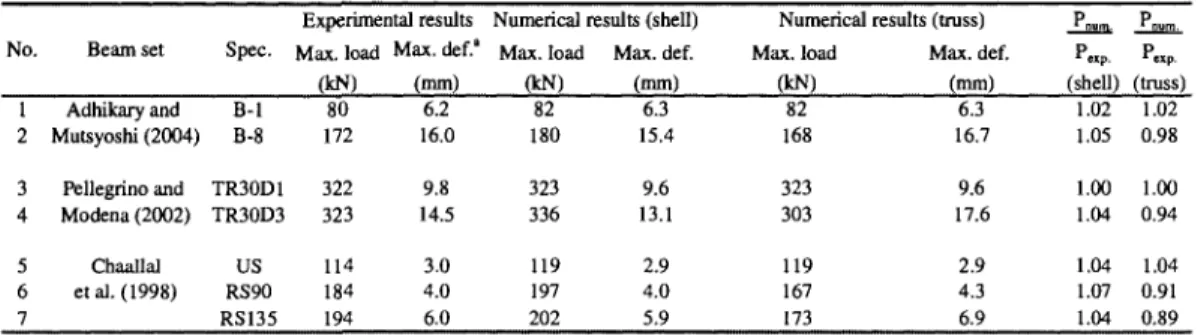
4.1 Comparisons between shell and truss modelling of FRP composites . . . . 82 4.2 Comparisons between the experimental and numerical failure modes . . . . 82
4.3 Comparison experimental and numerical results 97 4.4 Comparison between experimental and numerical failure modes 97
5.1 Geometrical dimensions of tested specimens 104 5.2 Material mechanical properties of tested specimens 105 5.3 CFRP shear-strengthening dimensions and configuration 106 5.4 Failure progress of the control specimens at different load levels 109
5.5 Failure progress of the strengthened specimens at different load levels . . . I l l
5.6 Comparison between experimental and numerical results 112 6.1 Concrete properties and shear-strengthening details of the tested specimens 131
6.2 Comparison between numerical and experimental results 135
7.1 Various ranges of independent variables 165 7.2 Comparison of FRP axial strain of shear-strengthened beams controlled by
debonding 171 7.3 Comparison of FRP shear strength of shear-strengthened beams controlled
LIST OF SYMBOLS
List of Symbols
Af = Area of F R P sheets
As = Flexural reinforcement ratio
Asv = Cross sectional area of shear steel stirrups a = Shear span length
a0 = Inner shear span length
a/d = Shear span length to effective depth ratio bc = Spacing between F R P strips
bf = W i d t h of F R P sheets
bf/bc = W i d t h ratio between F R P sheets to concrete memeber bw = W i d t h of concrete beam at the web
C = Matrix of concrete modulus of elasticity d = Effective depth of concrete section df = Effective depth of F R P stirrups Ec = Concrete modulus of elasticity E/ = F R P Tensile modulus of elasticity
Epi = Equivalent multiaxial modulus of elasticity in the principal directions Es = Secant modulus of elasticity
EfPf = Axial rigidity of F R P sheets fc = Concrete compressive strength fe = Effective stress of F R P sheets ffu = Ultimate stress in F R P sheets ft = Concrete tensile strength Gc = Concrete shear stiffness Gf = Interfacial fracture energy Gf = Concrete fracture energy h = Height of concrete section
k = Reduction factor for the characteristics of F R P sheets k\ = Factor of concrete strength
kv L Le n RL so sf Smax
t
fv
cv
nv
rv
s Wf Wfe aP
P
w 7/ ImF £ £fe £fed £fu £m &uc
Vn 9 V PS a <?m &pi Ou T~max = = = = = = = = = = = = = = = = = = = = = = = = = = = = = = = = = = = = Bond-reduction factor Beam lengthEffective bond length Number of F R P layers
Ratio between the remaining bonded length and the initial bonded length Corresponding interfacial slip to the maximum interfacial shear stress Central spacing between F R P strips
Maximum interfacial slip Thickness of F R P sheets Shear strength of concrete Shear strength of the section Required shear capacity Shear strength of steel stirrups W i d t h of F R P sheets
Effective width of F R P sheets Inclination of F R P orientation
Angle between the principal tensile stress and fibre directions
Interfacial width ratio between the F R P sheet to spacing between F R P strips Partial safety factor
Partial safety factor Incremental strain
Effective F R P axial strain Design F R P effective axial strain Ultimate strain in F R P sheets Concrete maximum strain Concrete ultimate strain Tension stiffness factor Shear reduction factor Inclination of diagonal crack Poisson ratio
F R P reinforcement ratio Incremental stress
Concrete maximum stress Principal stress
Concrete ultimate stress Maximum bond stress
Chapter 1
Introduction
1.1 General
Changing social needs, more stringent design standards, increasing safety requirements, and the deterioration of existing reinforced concrete infrastructure are steadily increasing the demands for structural strengthening. Worldwide, many concrete highway bridges suf-fer from chloride-induced deterioration, which is the result of using de-icing salts during severe winter conditions. Bridge authorities have the common problem of an ageing bridge infrastructure subjected to increasing traffic volumes and loads. Additionally, other prob-lems include design and construction errors, changes in design requirements and damage due to accidents. From the economic point of view, it is obviously untenable to replace all deficient structures. As an alternative, strengthening is an option to keep such structures safe.
Strengthening methods have been developed for flexural strengthening and used quite widely. Historically, steel has been the primary material used to strengthen concrete bridges and buildings [Swamy et al., 1987]. The bonding of steel plates to the tension face of the reinforced concrete is presented as an effective method for increasing the load carrying capacity, thereby reducing deflections and controlling cracking. However, using steel as a strengthening material faces some difficulty in the handling of the plates and in cutting to the shape, adds additional dead load to the structure and sometimes the instal-lation time may be the critical issue [Li et al., 2001]. Furthermore, the main shortcoming
with the steel plate strengthening techniques is the danger of corrosion at the epoxy-steel interface in a highly corrosive environment, which could adversely affect the bond strength between the steel plate and the beam. Researchers have been searching to eliminate the corrosion problem and to replace the steel plate by a corrosion-resistant material. FRP composites are emerging as a popular and attractive material for the strengthening of reinforced concrete structures. This material is successfully being used in the automotive, marine and aerospace sectors.
When two or more distinct materials are combined on a macroscopic scale to form a useful material, the resulting product is referred to as a composite material [Agarwal and Broutman, 1990]. The basic constituents of such a material are usually combined in order that the composite exploits their best qualities. As a result, the composite material exhibits overall properties that are superior to those of the individual constituents. The FRP is a composite material generally consisting of carbon, aramid, or glass fibres in a polymeric matrix (e.g., thermosetting resin). Among many options these composites may be in the form of laminates or flexible sheets. The laminates are installed by bonding them to the concrete interface with a thermosetting resin. The sheets are either dry or pre-impregnated with resin (pre-preg) and cured after installation onto the concrete surface.
Compared to the other strengthening methods, FRPs show an outstanding perfor-mance when they are used for strengthening reinforced concrete structures. The advan-tages offered by the FRP sheets are the high strength/weight ratio, the lower weight that makes the handling and installation significantly easier, corrosion resistance, and formability. The latter property is important when sheets need to be installed in certain locations. Technological advancements in manufacturing and processing methods make it economically viable to be used in the construction industry. Some disadvantages of FRPs are their low fire resistance (unless they are protected), long-term durability is not yet guaranteed and their brittle failure mode has to be addressed. The FRPs have poor fire performance compared to the concrete. Finally, a significant disadvantage is the scarcity of accepted design standards.
It is often necessary to pay great attention to the shear capacity of reinforced concrete beams because of the catastrophic nature of shear failures, which typically occur without any advance warning [Teng et al., 2004]. Shear strengthening can be required for various
1.1. GENERAL
reasons, such as to remedy design and construction errors or because of functional changes or environmental attacks. Sometimes, the need for shear strengthening can also arise as a consequence of flexural strengthening, which may result in a shear capacity that is less than the enhanced flexural strength. Various strengthening schemes including full wrapping, U-jacketing, and side bonding of the beam have been used where both continuous FRP sheets and strips are employed. However, the option of complete wrapping is not likely to be adopted in the field since most beams are cast monolithically with the slabs. The FRP sheets contribute to the shear resistance of the beam in the same way as that of internal steel stirrups. One of the major difficulties of externally shear-strengthened beams is the debonding of the FRP plates when an access for complete wrapping is not available. Some anchorage systems have been proposed to ensure the full utilization of the FRP sheets.
The finite element method is a powerful computational tool, which allows complex analyses of the nonlinear response of RC structures to be carried out efficiently and accu-rately. With this method, the importance and interaction of various parameters affecting the response of FRP shear-strengthened beams can be studied analytically. An outcome of such analyses is the development of reliable numerical models that can reduce the number of costly test specimens required for investigations of a given problem. However, experi-mental research remains necessary to validate the essential information for the numerical models, such as material properties. Experimental results are required to evaluate the accuracy of numerical results. In comparison to analyses on FRP flexural strengthening, theoretical investigations concerning the behaviour of reinforced concrete beams strength-ened in shear with FRP composites are rather limited. The numerical studies on FRP shear-strengthened beams are those of Kaliakin et al. [1996]; Arduini et al. [1997]; Malek and Saadatmanesh [1998a,b]; Al-Mahaidi et al. [2001]; Lee et al. [2001]; Wong [2001]; Lee [2003]; Santhakumar et al. [2004]; Elyasian et al. [2006]. In general, the numerical simulations provided quite satisfactory predictions of the overall behaviour of the shear-strengthened beams, in particular in terms of the overall load-deflection curves. However, most of these analyses did not explicitly address the details of the FRP/concrete interface and less attention has been paid to investigate the slip profiles along the FRP sheet depth. This thesis addresses this research gap.
Different parameters were observed to control the response of shear-strengthened beams. Experimental work is slowly increasing to build up a database of results of externally
shear-strengthened beams using FRP composites. However, the theoretical design models proposed in the literature are often contradictory. In order to determine the FRP shear contribution, the FRP effective strain is the most important and difficult term because it is the key factor in expressing the FRP shear contribution. Some researchers considered the FRP effective strain to be the ultimate strain in the FRP plies, others have taken it as a fraction of the bond stress between the FRP and concrete, and many researchers have related it to the axial rigidity of the FRP sheets and concrete compressive strength.
1.2 Scope
In this study, a three-dimensional model is developed to accurately simulate the behaviour of FRP shear-strengthened beams; it is based on the finite element package ADINA. In this model, the complex behaviour of the beams such as the bond-slip behaviour, concrete nonlinearity, and the different failure modes of the concrete and FRPs are taken into ac-count. Also, the scope of this dissertation includes the development of reliable elements that are able to simulate the response of FRP composites as well as the FRP/concrete interfacial behaviour. In order to demonstrate the validity of the finite element model, dif-ferent shear-strengthened beam applications such as side-bonded laminates and U-shaped wrapping configurations are investigated. Modelling simplifications and assumptions de-veloped during this research are presented. The numerical predictions are compared to published test data. Such a model is used to investigate the characteristics of bond-slip behaviour and the various parameters influencing a shear-strengthened beam. Finally, sta-tistical analyses are carried out using response surface methodology (RSM) and nonlinear regression analysis to develop an appropriate model for the effective FRP axial strain.
The accuracy of these models is evaluated by comparing the numerical predictions to the experimental data. Then, having verified the accuracy of the numerical models, parametric analyses are performed in order to gain better insight into the mechanisms governing the behaviour of such shear-strengthened beams. The significance of the present findings is discussed.
1.3. RESEARCH OBJECTIVES
1.3 Research Objectives
The principal objective of this study is to increase our knowledge about the behaviour of externally shear-strengthened beams using FRP sheets, to establish the role of the various parameters controlling the behaviour, and to resolve the points of conflict. The specific objectives of this investigation are:
• To develop and validate an accurate numerical model for the simulation of the behaviour of externally shear-strengthened beams.
• To use this model to examine the role of the various parameters affecting such behaviour.
• To deliver an appropriate design expression that describes the effective FRP axial strain for the case of debonding.
The limitations of this research are:
• A reinforced concrete beam without any level of pre-stressing is assumed. • Only static loads are considered.
• The research is limited to slender beams (a/d > 2; where a is the shear span, and d is the effective depth [CSA-A23.3-04, 2004]).
• The effect of long term deflections and temperature effects are not taken into account.
1.4 Outline
The research presented herein is organized into different chapters. In this chapter, the objectives, backgrounds and scope of the study have been outlined. Previous studies rele-vant to the shear strengthening of reinforced concrete beams are summarized in Chapter 2. The development, analyses and specimens investigated to develop a reliable numerical
model are the focus of Chapter 3. The comparisons between the numerical and experi-mental data are given in Chapter 4. Chapter 5 describes the experiexperi-mental and numerical program of the size effect of shear-strengthened beams. The validation of the numerical predictions against various configurations of FRPs is presented in Chapter 6. In Chap-ter 7, parametric studies and a design expression for the effective FRP axial strain are reported. Concluding remarks and recommendations for further studies are outlined in Chapter 8.
C h a p t e r 2
L i t e r a t u r e Review
2.1 I n t r o d u c t i o n
The purpose of this chapter is to provide a review of FRP shear-strengthened reinforced concrete beams. A brief description of the behaviour, factors controlling the behaviour, design algorithms and finite element models will be presented. In addition, this survey covers the use of anchorages at the ends of the FRP composites to avoid debonding failure modes.
2.2 Techniques for t h e Shear Strengthening of Beams
The strengthening of concrete members is usually accomplished by the construction of external reinforced concrete jackets, by epoxy bonding of steel plates to the side faces of the members, by external post-tensioning, or by fibre reinforced polymers (Figure 2.1). A suitable strengthening scheme needs to be selected for a given situation based on a number of factors, which may include:
• economical considerations
Figure 2.1: Examples of shear-strengthening techniques
• the position of the beam whether it can be strengthened by full or potential wrap-ping.
2.2.1 T r a d i t i o n a l Techniques
For the shear strengthening of existing concrete structures, a number of techniques have been developed to satisfy the demands for the increase of the shear bearing capacity. Among these techniques that have been developed, certain ones have experienced reason-able levels of use and success. For example, external post-tensioning, epoxy bonding of steel plates to the tension faces of the members, and addition of reinforced concrete outside the existing section are all recommended strengthening procedures. The most common problem with these techniques is that they are quite inconvenient, often requiring extensive equipment, time consuming and labour intensive.
Post-tensioning is a technique that has been used effectively to increase the shear capacity of both reinforced and prestressed concrete members either by internally or ex-ternally placed post tensioning to an existing beam web. With this type of upgrading, active external forces are applied to the structural member using post-tensioned cables externally or internally to resist new loads, as shown in Figure 2.2. The main advantages of this technique are that it provides immediate active strengthening, which relieves the overstressed conditions of the beam web, and its minimal additional weight of the repair system [Emmons, 1993; Deniaud, 2000; Suntharavadivel and Aravinthan, 2006; Shamsaia
2.2. TECHNIQUES FOR THE SHEAR STRENGTHENING OF BEAMS
UmmallyPtaMdPott-ftOKOTllo Ext«rntfy Ptoc«0 PoB-Wwonins
Figure 2.2: Post-tensioning shear-strengthening technique [Deniaud, 2000]
et al., 2007]. The disadvantages of this technique are that the deck overlay needs to be removed and large numbers of holes must be drilled through the member. There is also some inconveniency for the user since one part of the bridge must be closed to facilitate the drilling process. The amount of steel weight added to a structure can also increase the dead load to the concrete girders.
Strengthening of concrete structures by means of bonding steel plates to the side faces of the beam was found to increase the shear capacity of the section [Taljsten, 1994]. Steel plate bonding found its way relatively quickly into practice [Barnes et al., 2001; Adhikary et al., 2000; Adhikary and Mutsuyoshi, 2006]. External steel plates are attached to the concrete with epoxy and/or mechanical anchorages, which are placed perpendicular to the shear cracks or to the beam longitudinal direction, as shown in Figure 2.3. Steel plate bonding was popular because of its various advantages, which include a minimal increase in the beam size, the simplicity, cost-effectiveness and efficiency. Although this method technically performs well for shear strengthening, it suffers from some drawbacks. The deterioration of the bond at the steel plate-concrete interface in a harsh environment by corrosion requires a lot of maintenance. The steel plate bonding operations require heavy lifting gear and full scaffolding for handling. During the curing operations, the plates require external pressure. The steel plates are always delivered in limited lengths (in the case of flexural strengthening of long elements) and they are difficult to apply to curved surfaces. Another drawback is the transportation problem [An et al., 1991].
Another technique of shear strengthening is to enlarge the cross section of the member. An overlay can be cast either around the web or over the top slab or by a combination of both (Figure 2.4). If adhesion between the new and old concrete can be assured, this technique is good from a technical standpoint. A new wider section will give a higher shear
Figure 2.3: Deficient beam in shear strengthened with steel plates [Barnes et al., 2001]
BMnOwtor Qvwtjfon-fopolSu
Figure 2.4: Concrete jacketing for slabs and beams [Deniaud, 2000]
capacity for the structure and reduce the deflections. Obviously, this technique increases the dead load and in some cases it is not permissible due to the lack of the capacity of substructure [Deniaud, 2000].
2.2.2 F i b r e Reinforced P o l y m e r Technique
Fibre reinforced polymers have found their way as strengthening materials for reinforced concrete structures in applications where conventional strengthening techniques may be problematic [Triantafillou, 1998]. The rapidly expanding body of literature in this area, along with the corresponding increase in the level of activity, confirms the fact that these new materials are progressively gaining wider acceptance by the civil engineering com-munity. Nowadays, FRP systems are used in several applications to strengthen existing RC structures instead of the traditional systems using steel, as illustrated in Figure 2.5. FRPs may be attached on a beam or a slab tension surface to provide additional fiex-ural strength, on the sides of a beam to provide additional shear strength, or wrapped
2.2. TECHNIQUES FOR THE SHEAR STRENGTHENING OF BEAMS
Figure 2.5: Examples of FRP strengthening for concrete structures [Sika Carbo Dur 2005]
around columns to provide confinement and additional ductility. Furthermore, concrete and masonry walls may be strengthened to resist seismic and wind loads, concrete pipes may be wrapped with FRP sheets to resist higher internal pressures, and tanks may be strengthened to withstand higher pressures [Neale, 2000].
The existing shear capacity of reinforced concrete beams can be enhanced by bonding FRP composites to the web, typically with the dominant fibre direction perpendicular to the shear crack or to the length of the member. There are a variety of FRP systems and arrangements reported in the literature. The type of arrangement used strongly influences the contribution of the externally bonded FRP to the shear load capacity. Apart from the common advantages of FRPs such as corrosion resistance and high strength-to-weight ratios, the versatility of FRP in coping with different sectional shapes and corners is also a benefit for shear strengthening applications [Teng et al., 2002]. Figure 2.6 illustrates a concrete bridge shear-strengthened with FRPs.
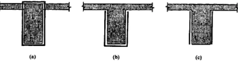
Various plate schemes have been used to increase the shear resistance of reinforced concrete beams. These schemes include bonding the plates to the sides of the beam only, bonding U-jackets to both sides and the tension face, or wrapping the plates around the whole cross-section of the beam. Different bonding schemes are shown below in Figure 2.7. The complete wrapping of the entire cross section is the most effective method of shear strengthening with FRP, as shown in Figure 2.7(a). Typically, this is not practical from a constructability standpoint. The presence of monolithic slabs or other supported elements
Figure 2.6: Concrete bridge shear-strengthened with FRPs
(•» (b) (c)
Figure 2.7: Various schemes for wrapping FRP shear strengthening: (a) complete wrapping,
(b) U-wrapping, (c) side-bonding
often prevents wrapping the sheet around the top of the section. One option might be to drill holes through the slab and wrap FRPs around the section. However, this method is complicated and costly.
The most common method of shear strengthening is to wrap the sides and bottom of the section. This method is referred to as a U-wrap and shown in Figure 2.7(b). The U-wrap is practical and is effective in increasing the shear carrying capacity. In some situations, it may not be possible to wrap the full height of the section. Shear strengthening is still possible by placing the reinforcement on both sides of the section (Figure 2.7c).
Shear repair schemes have been examined either by using strips or continuous sheets as illustrated in Figure 2.8. The advantages of the strips include the ability to select their number based on the shear strength requirements, and the ease of achieving a uniform epoxy thickness. The strips may be spaced at an equal distance throughout the shear span or at a different spacing. The plates may also be oriented at different angles to meet different reinforcing requirements as shown in Figure 2.9. The best way for increasing
2.2. TECHNIQUES FOR THE SHEAR STRENGTHENING OF BEAMS
Y y I v » v >lf 4> I
•
( b )Figure 2.8: Various FRP shear strengthening distributions: (a) continuous reinforcement, (b)
FRP strips
on
Figure 2.9: Sheets with their fibres oriented in various primary directions: (a) inclined sheets,
(b) vertical sheets
the shear capacity of the section is bonding the plates parallel to the principal tensile stresses. This is achieved by the use of inclined sheets, Figure 2.9(a). However, vertically oriented sheets are easier to install and may reduce the total length of the wrap, as shown in Figure 2.9(b).
Bi-axial F R P reinforcement is achieved by placing two unidirectional F R P plies in mutually perpendicular directions as shown in Figure 2.10. T h e sheet in the primary direction acts to provide most of the reinforcement, while the sheet in the secondary direction limits shear crack openings and provides anchorage for the sheet in the primary direction.
CEO
fttPl
Figure 2.10: Beams with bi-axial shear reinforcement: (a) vertical bi-axial sheet, (b) inclined
Figure 2.11: Beam with vertical NSM FRP rods for shear strengthening Lorenzis and Nanni [2001]
In addition, shear strengthening can also be achieved using near-surface mounted (NSM) FRP bars, see Figure 2.11. This method is relatively new with limited research and more studies are needed [Lorenzis and Nanni, 2001].
2.3 Concept of Shear Strengthening using F R P
com-posites
The shear strengthening of reinforced concrete structures using FRP plates has now been used for over a decade. Most researchers have idealized the external bonding of the plates in a manner analogous to internal steel stirrups, assuming that the contribution of the plates to the shear capacity emanates from the capacity of the plates to carry tensile stresses at a constant strain. However, the effectiveness of the external shear strengthening plates and their contribution to the shear capacity of the reinforced concrete beam depends on the mode of failure, which may occur either:
• by peeling-off • by tensile fracture.
The failure modes and the degree of strength enhancement are strongly dependent on the details of the bonding schemes and the anchorage methods. The problem of the anchorage arises from a practical difficulty. This difficulty is associated with the technique
2.4. SHEAR BEHAVIOUR OF REINFORCED CONCRETE BEAMS
of strengthening or repairing the existing structure and does not allow for bonding the plate in the form of a closed continuous loop around the whole cross section of the beam. Based on the available experimental data, side-bonded plates are very vulnerable to premature failure. Full wrapping is the most effective technique but it is not adopted in the field since most beams are cast monolithically with a slab, and U-jacket is lying in between. Therefore, full wrapping should be used whenever is possible, followed by U-jacketing.
Since shear strengthening often forms a key part of an effective strengthening strategy for reinforced concrete structures, numerous shear strengthening studies have been carried out since the 1990s (e.g. Uji [1992]; Al-Sulaimani et al. [1994]; Chajes et al. [1995]; Alexander and Cheng [1996]; Araki et al. [1997]; Arduini et al. [1997]; Sato et al. [1997b]; Hutchinson et al. [1997]; Triantafillou [1997]; Chaallal et al. [1998a,b]; Khalifa et al. [1998]; Malek and Saadatmanesh [1998a,b]; Fanning and Kelly [1999]; Deniaud and Cheng [2001a]; Kachlakev and McCurry [2000]; Khalifa and Nanni [2000]; Triantafillou and Antonopoulos [2000]; Khalifa and Nanni [2002]; Pellegrino and Modena [2002]; Taljsten [2003]; Wong and Vecchio [2003]; Adhikary and Mutsuyoshi [2004]; Bousselham and Chaallal [2004a]; Teng et al. [2004]; Cao et al. [2005]; Carolin and Taljsten [2005]; Zhang and Hsu [2005]; Bousselham and Chaallal [2006b]; Pellegrino and Modena [2006]; Leung et al. [2007]; Monti and Liotta [2007]; Mosallam and Banerjee [2007]; Lee and Al-Mahaidi [2008]).
2.4 Shear Behaviour of Reinforced Concrete Beams
2.4.1 Shear Behaviour of RC Beams without F R P
Strengthen-ing
The shear behaviour of un-strengthened reinforced concrete beams was reviewed in ASCE [1998] and Kong and Evans [1990]. Shear is an important but controversial topic in structural concrete design. In design, it is generally desirable to ensure that the ultimate strengths are governed by flexure rather than by shear; except in seismic design. Small deflections and little warning characterize shear failures before the occurrence of failure. It is now known that the shear resistance mechanism of a simply supported reinforced concrete beam is not a function of a single variable. The mode of diagonal failure has been found by experiment to be strongly based upon the shear-span/effective depth ratio,
Shekr-u<R^n-«4on t'W\ur»l Mi>n*ra Sttt-njtili Simigth
. J . . . . . i _ _J. J_- i.._
I 2 -> J S 6 Knliii of Nht-ar Span In lltam IK-plh. o/rf
Figure 2.12: Variation of shear strength with shear-span/effective depth ratio [Mosallam and
Banerjee, 2007]
as illustrated in Figure 2.12. The shear behaviour of a beam is governed by some secondary parameters, such as:
• concrete strength • tension steel • aggregate type • beam size.
The shear strength of a beam is substantially increased by the use of shear reinforce-ment. The shear reinforcement increases the ductility of the beam and considerably limits the crack width a n d reduces the likelihood of a sudden and catastrophic failure. The general principle of design of shear assumes t h a t concrete provides t h e primary shear re-sistance of the beam and t h a t the shear force in excess of the concrete shear rere-sistance has to be resisted by the internal shear reinforcement. Before diagonal cracking, it is assumed the external applied force produces few stresses in t h e web reinforcement. When the di-agonal crack forms, any web bar which intersects t h e didi-agonal crack will suddenly carry a portion of t h e shear force. Web bars not intersected with t h e diagonal crack remain slightly stresses. As t h e external applied force is increased, t h e most stressed stirrups start to yield. If the crack continues to widen, the neighbouring stirrups reach their yield
2.4. SHEAR BEHAVIOUR OF REINFORCED CONCRETE BEAMS
limit and start to deform until all the stirrups crossing the cracks start to yield. The shear strength carried by the web reinforcement remains stationary at the yield value and the subsequent increase of the external force will be carried by the concrete shear strength. When the diagonal crack widens, the aggregate interlock becomes less effective and the dowel action of the tension reinforcement increases rapidly. Failure of the beam finally occurs either by the dowel splitting of the concrete along the longitudinal reinforcement or by crushing of the concrete in the compression zone. Reinforced concrete beams without transverse steel fail with one principal diagonal crack whereas those with steel stirrups fail with a diagonal cracked area.
2.4.2 Shear Behaviour of F R P Shear-Strengthened RC Beams
The available evidence from experiments indicates a basic difference in the mode of failure of a reinforced concrete beam strengthened in shear with externally bonded FRP plates from that of a beam reinforced with internal steel stirrups [Swamy et al., 1999; Khalifa et al., 1998; Triantafillou and Antonopoulos, 2000; Teng et al., 2002]. In the case of beams with internal steel stirrups, the shape and position of the latter ensure sufficient anchorage, and failure is determined by the tensile strength of the links. By contrast, for beams reinforced with externally bonded FRP plates, the failure criterion is governed primarily by the anchorage efficiency, rather than by the tensile strength of the FRP plates.
2.4.2.1 Shear Failure Controlled by FRP Rupture
This type of failure occurs most often with a diagonal shear tension crack. Vertical flexural cracks originating from the tensile face occur first. A crack near the support may propagate towards the loading point and may become an inclined crack. In some cases, a diagonal crack may appear abruptly. The sudden formation of a diagonal crack causes an abrupt load transfer to a localized region of the FRP intersecting the diagonal crack. As the width of the diagonal crack increases, the maximum strain in the FRP strips eventually reaches its maximum strain, which often occurs at a strain lower than the ultimate strain of the FRP [Triantafillou and Antonopoulos, 2000; Teng et al., 2002].
Figure 2.13: Shear rupture failure of the FRP sheets [Carolin and Taljsten, 2005]
The failure is initiated at the most highly stressed point in the FRP strip intersected by the shear crack. When the FRP strip reaches its ultimate tensile strength, then rupture of the FRP plates propagates along the diagonal shear crack in the concrete, leading to total failure of the beam in a brittle manner. After rupture of the first strip the stresses redistribute to the other fibres and so on until all strips are broken. Figure 2.13 shows the rupture failure of FRP plates. Partial debonding of the FRP sheets from the beam sides often occurs prior to rupture in most cases whilst only the FRP plates remain bonded to the top and bottom face of the beam. However, the eventual failure is due to the rupture of the FRP strips. The results show that the FRP strips do not close the cracks, but help to delay the occurrence and propagation of cracks. All of the beams with full wrapping of the FRP composites around the beam and some with U-jackets fail in this mode. The tensile strength of the FRP can always be fully utilized if there is a sufficient bond length, which is called the effective bond length. Beyond this length there is no further transfer of load to the FRP. The effective bond length is based on the concrete strength, modulus of elasticity, and thickness of the FRPs [Chajes et al., 1995; Triantafillou, 1998; Triantafillou and Antonopoulos, 2000; Deniaud and Cheng, 2000; Li et al., 2001; Taljsten and Carolin, 2001; Teng et al., 2002; Carolin and Taljsten, 2005].
2.4.2.2 Shear Failure Controlled by FRP Debonding
A shear-strengthened reinforced concrete beam may fail due to the debonding of the FRP plates from the sides of the beam. This kind of failure occurs when the concrete
2.4. SHEAR BEHAVIOUR OF REINFORCED CONCRETE BEAMS
(a) (b)
Figure 2.14: Shear debonding failure of the FRP sheets in: (a) U-wrap [Khalifa and Nanni,
2000], (b) side-bonded [Pellegrino and Modena, 2002]
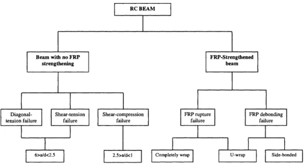
surface strength is too low, the epoxy used has low shear strength or the length of the F R P strips is not sufficient to transfer the shear forces between the reinforcement and the concrete. After the formation of the shear crack along the depth of the beam and with the increase of the external applied load, the debonding initiates at the F R P plates crossing the crack. T h e debonding is initiated above and below the shear cracks at the areas where the development length is not sufficient, with a concrete layer attached to them. T h e bonded area progressively decreases as debonding of F R P s proceeds outwards away from the shear crack location towards both ends of the strip. T h e studies reveal that strips intercepting the shear crack close to the end have small areas of debonding. Those intercepting the shear crack near mid-height show greater areas of debonding. This results in an instantaneous increase in the load carried by the vicinity, which leads to a rapid propagation of the debonding of the F R P sheets over the shear cracks, combined with beam failure. In some cases, the load is not able to increase beyond the first peak reached at the failure of the first strip. In other cases, the maximum load may occur after a few strips have already failed. Consequently, first strip failure does not correspond to the ultimate shear capacity. The deflection of beams failing in this mode is usually very limited. Figure 2.14 presents shear-debonding failure of F R P sheets. Available test results indicate t h a t all beams strengthened with side-bonded F R P s , and many beams strengthened with U-jackets, fail in this mode [Khalifa and Nanni, 2000; Taljsten and Carolin, 2001; Teng et al., 2002]. A diagram of the shear behaviour of a reinforced concrete beam is shown in Figure 2.15.
Beam with no FRP strengthening Diagonal-tension failure Shear-tension failure 6>a/d<2.5 RC BEAM FRP-Strengthened beam Shear-compression failure FRP rupture failure 2.5>a/d<l FRP debonding failure
Completely wrap U-wrap Side-bonded
Figure 2.15: Diagram of the shear behaviour of reinforced concrete beams
2.5 P a r a m e t e r s Influencing Shear-Strengthened Beams
The success of FRPs in shear strengthening is a result of a considerable research effort carried out in recent years. Results of these studies led to interesting conclusions, partic-ularly regarding the parameters influencing the behaviour of shear-strengthened beams, such as the FRP strengthening scheme. The effectiveness of the FRP strengthening de-pends on its failure mechanism. Whether debonding or fracture will occur first dede-pends on many factors such as the bond conditions, the available bond length, type of attachment of the FRP plates to the concrete substrate, the thickness and stiffness of the laminates and other factors [Khalifa and Nanni, 2000; Bousselham and Chaallal, 2004a]. Addition-ally, an exhaustive review of research studies on shear-strengthening revealed that other parameters linked to the shear resistance mechanism of shear-strengthened beams have not been sufficiently documented. The shear-span-to-depth ratio as well as the trans-verse steel reinforcement are among these parameters. Research studies that have been carried out to investigate these parameters are somewhat contradictory and to a certain degree controversial [Triantafillou and Antonopoulos, 2000]. Many aspects are still not fully verified due to the relatively large scatter observed in the research studies. The
pa-2.5. PARAMETERS INFLUENCING SHEAR-STRENGTHENED BEAMS
rameters influencing an externally shear-strengthened beam are presented at Figure 2.16. The parameters are grouped according to their types to:
• beam dimensions • strengthening schemes
• FRP dimensions and characteristics.
as discussed below.
2.5.1 B e a m Dimensions
• An increase of the steel shear reinforcement is reported to reduce the FRP shear con-tribution [Uji, 1992; Sato et al., 1996; Taerwe et al., 1997; Aedy et al., 1999; Swamy et al., 1999; Deniaud and Cheng, 2000; Li et al., 2001; Neto et al., 2001; Wong, 2001; Chaallal et al., 2002; Pellegrino and Modena, 2002; Deniaud and Cheng, 2003; Lee, 2003; Li et al., 2003; Bousselham and Chaallal, 2004a; Carolin and Taljsten, 2005; Bousselham and Chaallal, 2006b,a; Elyasian et al., 2006; Pellegrino and Modena, 2006; Grande et al., 2007; Leung et al., 2007]. Malek and Saadatmanesh [1998a] conducted a model study using the FEA package ABAQUS to simulate the be-haviour of shear-strengthened beams. From this model, the authors reported that the FRP sheets shear contribution does not depend on the presence of steel stirrups. • The influence of the concrete strength to the effective strain of the FRP plies was only studied by Deniaud and Cheng [2000]. They reported that the effective strain of the FRP is observed to increase proportionally with the increase of the concrete strength. Khalifa and Nanni [2000], Triantafillou and Antonopoulos [2000] and Elyasian et al. [2006] confirmed the same trend.
• Khalifa and Nanni [2002] observed from their experimental works that the shear span to effective depth ratio (a/d) influences the FRP shear contribution, which appears to decrease with the decrease of the ratio. This is opposed to what was reported by Cao et al. [2005], who stated that the shear capacity increases with the decrease of shear span/depth ratio. From the tests conducted by Mitsui et al. [1998], it is
![Figure 2.11: Beam with vertical NSM FRP rods for shear strengthening Lorenzis and Nanni [2001]](https://thumb-eu.123doks.com/thumbv2/123doknet/3342862.96496/35.922.365.591.163.333/figure-beam-vertical-nsm-shear-strengthening-lorenzis-nanni.webp)

![Figure 3.9: Shear strengthening configuration and loading arrangement [Pellegrino and Mod- Mod-ena, 2002]](https://thumb-eu.123doks.com/thumbv2/123doknet/3342862.96496/90.922.190.791.153.335/figure-shear-strengthening-configuration-loading-arrangement-pellegrino-mod.webp)
![Figure 3.10: Shear strengthening configurations and loading arrangement [Chaallal et al., 1998b]](https://thumb-eu.123doks.com/thumbv2/123doknet/3342862.96496/92.922.224.758.292.781/figure-shear-strengthening-configurations-loading-arrangement-chaallal-et.webp)
![Figure 4.5: Applied load-central deflection relationships for TR30D3 and TR30D2 beams of Pellegrino and Modena [2002]](https://thumb-eu.123doks.com/thumbv2/123doknet/3342862.96496/104.922.324.666.154.386/figure-applied-central-deflection-relationships-beams-pellegrino-modena.webp)
