Angled Roller Mecanum Wheel Design That
Exhibits Speed Reduction
by
All Alsalih Abdalla
Submitted to the Department of Mechanical Engineering
in partial fulfillment of the requirements for the degree of
Bachelor of Science in Engineering as recommended by the
Department of Mechanical Engineering
at the
MASSACHUSETTS INSTITUTE OF TECHNOLOGY
February 2018
@
Massachusetts Institute of Technology 2018. All rights reserved.
Signature redacted
A uthor ...
Department of Mechanical Engineering
Dec 13, 2017
Signature redacted
Certified by...
...
H. Harry Asada
Ford Professor of Engineering
Thesis Supervisor
Signature redacted
Accepted by...
Rohit Karnik
Associate Professor, Department of Mechanical Engineering
MASSACHUSES INSTITUTE
OF TECHNOLOGY
SEP 13
2018
Angled Roller Mecanum Wheel Design That Exhibits Speed
Reduction
by
Ali Alsalih Abdalla
Submitted to the Department of Mechanical Engineering on Dec 13, 2017, in partial fulfillment of the
requirements for the degree of
Bachelor of Science in Engineering as recommended by the Department of Mechanical Engineering
Abstract
This thesis presents the testing of speed reduction exhibited by custom angle mecanum wheels. A simple trigonometric model is put forth for the speed reduction, along with the kinematic analysis and simulation of a 3-wheeled-vehicle. Then a 150 mecanum wheel is designed and built, along with a testing fixture allowing it to freely move in the direction the roller pushes towards. This fixture also allowed the collection of the encoder data from the motor and the linear distance the wheel travels. Based on that, the detected speed reduction ratio was 4.9:1, as opposed to the modeled ratio of 3.9:1. This discrepancy is likely cause by the absence of slippage in our model, the
jiggle in the wheel's motion, the compliancy of the surface it rotates on, as well as
the uncertainty from the linear distance measurement. Thesis Supervisor: H. Harry Asada
Acknowledgments
I would like to start by thanking my parents, without whose love and support I would certainly not be where I am today. They have taught me all that I know about the value of passionate, responsible, and hard work. I want to thank my sister Lena and brother Sasha, who have consistently split my life's burdens with me. They don't know how much they've inspired me to continue learning.
To my friends, too many to list on this page, I am so incredibly grateful for your love, support, and company these past years. You are a light in my life. To Hassan Kane, Usman Ayyaz and Abubakar Abid, I am so indebted to you for the truly immeasurable influence you have had on me.
To the Muslim Students' Association, one of the most powerful and loving com-munities I have known, thank you for welcoming and nurturing me these past years.
I would like to especially thank my friend Mubarik Mohamoud for the many nights
of his help in this project. My supervisor Daniel Gonzalez who has truly been the best teacher I've had at MIT. Simply enough, there would be no thesis without him. And Professor Asada for his guidance and teaching throughout this project.
Contents
1 Introduction and Background
1.1 M otivation . . . . 1.2 Contributions and Overview . . . .
2 Geometry and Analysis
2.1 Wheel Geometry and Model 2.2 Vehicle Geometry and Analysis
2.2.1 Inverse Kinematics
2.2.2 Vehicle Simulation
3 Design and Implementation
3.1 W heel Design . . . . 3.2 W heel Prototype . . . .
4 Experiment
4.1 Fixture Design and Build . . . . 4.2 R esults . . . .
5 Conclusion and Recommendations for Future Work 5.1 Experiment Critique and Recommendations . . . . . 5.2 Conclusion . . . . 13 14 15 17 . . . . 17 18 . . . . 18 . . . . 20 23 23 25 27 27 31 33 33 34
List of Figures
1-1 The wheel throughout centuries. Only minor changes with basic design
concept the sam e. [6] . . . .. . . . . 13
1-2 The Omniwheel and the Mecanum wheel, both shown above, allow a vehicle to move in any direction. . . . . 14
1-3 Full CAD design of custom angle mecanum wheel and testing fixture. 16 2-1 Illustration of traction on a mecanum wheel[1]. The non-perpendicularity of the rollers reduces its speed . . . . . 17
2-2 Three-Mecanum-wheeled vehicle used for kinematic analysis. [5] . . . . 18
2-3 Diagram illustrating parameters in kinematic model[4] . . . . 19
2-4 Three-wheeled vehicle simulation. . . . . 20
3-1 Front view of the 150rnecanum wheel we designed. . . . . 24
3-2 Cross section of one of the rollers showing the shoulder screw, flanged bearings, and threaded insert that ensure stability but maintain fric-tionless spin . . . . . 24
3-3 Side view of our mecanum wheel design. . . . . 25
3-4 Assembled 15*prototype. . . . . 26
4-1 Full CAD design of testing fixture. . . . . 27
4-2 Close-up view of wheel and motor assembly. . . . . 28
4-3 Bottom view of fixture. . . . . 29
4-4 Assembled fixture ready to test the wheel. . . . . 29
4-6 Close-up of motor wheel assembly . . . . 30 5-1 Mecanum wheel with a parallel roller set-up that would reduce jiggle. [3] 34
List of Tables
4.1 Results of the 15*mecanum wheel with a measured diameter of 5.93" running 3 revolutions. . . . . 31
Chapter 1
Introduction and Background
The invention of the wheel dates back millennia. It can be reasonably credited as the simplest yet most vital tenet in all or most forms of travel by land. Despite this, since its creation, the wheel has seen very little innovation on its design. Perhaps its manufacturing has changed, or the materials it's composed of, but the simple design remains as a disk spinning on an axle with a bearing.
Figure 1-1: The wheel throughout centuries. Only minor changes with basic design concept the same.[6]
functionality. One of these modifications is the creation of the Omniwheel, an omni-directional wheel first patented by J. Grabowiecki[9] in 1919, then patented as a variant by Josef F. Blumrich in 1972[7]. What gives the wheel the ability to move omnidirectionally are rollers attached to it's hub that can passively rotate about the spokes holding them in place. The same year Blumrich patented the Omniwheel, another design for a wheel that was seeking the same functionality was patented by Bengt Erland Ilon and came to be known as the Mecanum wheel[8].
(a) The Omniwheel[2] (b) The Mecanum Wheel[1]
Figure 1-2: The Omniwheel and the Mecanum wheel, both shown above, allow a vehicle to move in any direction.
Similar to the Omniwheel, a Mecanum wheel has rollers on its hub that passively rotate about the spokes holding them. The only difference is that these rollers' axes of rotation are not perpendicular to that of the wheel (as in the omniwheel) but rather they are at a 45'angle with respect to it.
It is on top of this wheel that we build our concept for a custom angle mecanum wheel design exhibiting speed reduction.
1.1
Motivation
Two particular features that are missing from most wheel setups are space and light-ness. The major contributor to this are gears. Gearboxes between motors and wheels
typically take too much space and increase weight, but they are necessary for perfor-mance. This makes having a direct drive setup for a wheel a lucrative feature. To solve this problem, a wheel needs to be designed that can manipulate performance the way gears do, without them.
Mecanum wheels can do this, or at least, can manipulate the performance of the Omniwheel. This is explained as follows; if a motor is connected to a 6" Omniwheel and spins it one revolution, the rollers (along with their axis of rotation) are per-pendicular to the motor shaft and so have complete traction with the ground. This means they do not spin at all and the wheel moves 6" x7r forward. Suppose these rollers were instead mounted parallel to the motor shaft. The wheel would spin but not move forward at all, since rollers would spin in the opposite direction eliminating any traction the wheel has with the ground. So, at 900, the wheel moves at full speed, and at 00, the wheel moves at zero speed. What is seen here is a different speed output based on the angle the rollers are mounted. It is this speed reduction that leads to effective gearing. In a mecanum wheel, the rollers are mounted at 450 with respect to the motor shaft. Since the wheel only has traction along the roller, it should not be able to move forward the full distance of 6" x7r, but rather there should be some speed reduction.
But the Mecanum wheel only comes in the standard 45' angle, and so does not optimize the effective gearing it provides. In fact, there does not currently exist a custom angle Mecanum wheel, leading us to design, build, and test the speed reduction of our own. There are also other problematic features in the Mecanum wheels that do exist. There is often jiggle in the movement of the wheel, as well as some friction in the spinning rollers. To optimize the speed reduction these problems must be solved.
1.2
Contributions and Overview
This thesis presents the analysis, design, and testing of custom angle Mecanum wheels and their exhibition of speed reduction.
Figure 1-3: Full CAD design of custom angle mecanum wheel and testing fixture.
kinematic analysis of a vehicle driven by them. It also includes a vehicle simulation that visualizes the parameters and their effect on the kinematics.
Chapter 3 presents the parametric CAD design of the wheel, illustrating the several design challenges with custom angles and the choice of a 150 Mecanum wheel. It also details the mechanical components of the wheel as well as its implementation into a physical prototype.
Chapter 4 presents the design of the speed reduction experiment and testing fix-ture, as well as analysis of the results with respect to our speed reduction model.
Finally, Chapter 5 discusses the conclusion, recommendations and potential future work.
Chapter 2
Geometry and Analysis
2.1
Wheel Geometry and Model
We start by using the standard Mecanum wheel where rollers are placed at a 450
angle with respect to the motor shaft. This is outlined in Figure 2-1.
Figure 2-1: Illustration of traction on a mecanum wheel[1]. The non-perpendicularity of the rollers reduces its speed.
The force from the motor shaft (red arrow) is pushing the wheel forward, but since the wheel only has traction along the rollers, it can only move at a trajectory
Figure 2-2: Three-Mecanum-wheeled vehicle used for kinematic analysis. [5]
of the wheel becomes:
V = w x sin(6) (2.1)
where w is the angular velocity of the motor shaft and 6 is the angle the axis of
the rollers makes with the axis of the wheel (450 in the case of the standard mecanum wheel). That is to say a 150 mecanum wheel (as we will later design and test) would have its speed reduced to sin(15') = 0.259, or about a quarter, of the angular velocity. That 150 speed reduction translates to a 1:4 gear ratio, allowing the wheel to carry four times the load of a wheel with its same diameter, still with direct drive. Equation 2.1 is the basic speed reduction model we will test in Chapter 4.
2.2
Vehicle Geometry and Analysis
2.2.1
Inverse Kinematics
This section relies heavily on the work of A. Gfrerrer in his paper "Geometry and Kinematics of the Mecanum Wheel" [5] where he includes a derivation for the kine-matic model below. He presents a three-wheeled vehicle as shown in Figure 2-2.
The important parameters involved in the kinematics are illustrated in the
dia-18
r
00
N
N
Figure 2-3: Diagram illustrating parameters in kinematic model[4]
gram in Figure 2-3. For i = 1, 2, 3; let ai denote the angle between each wheel's axis and the x-axis at the center of the vehicle. Let r be the radius of each wheel, ai: and aiy the center of each wheel (with respect to the center of the vehicle), and let 6 denote the roller angle as before.
Gfrerrer finds that the solution to the inverse kinematics problem, whereby v, (vehicle's x-axis velocity), vy (vehicle's y-axis velocity), and w (vehicle's angular ve-locity) are given, and the desired variables are wi, w2, and w3 (respective wheel angular
velocities), is as shown below:
1
II
W2 =- M Vy r sin W3J LW] (2.2) Where M isFigure 2-4: Three-wheeled vehicle simulation.
cos(ai + 6) sin(ai + 6) a1 sin(ai + 6) - aiy cos(ai
+
6)M = cos(.a2 + 6) sin(a2 + 6) a2x sin(a2 + 6) - a2y cos(a2 + 6) (2.3) [cos(a3 + 6) sin(a3 +
6)
al, sin(a3 + 6) - a3y cos(a3 + 6)2.2.2
Vehicle Simulation
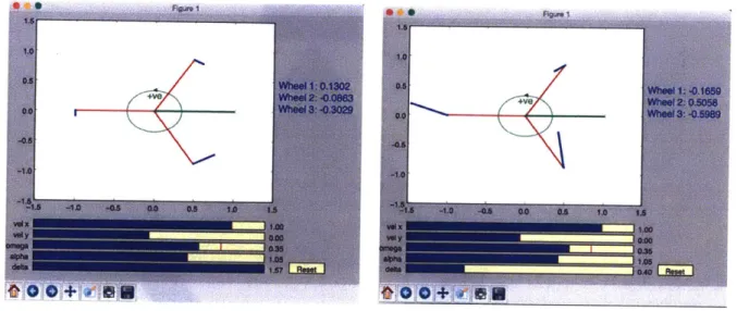
Based on the model from the previous section, we learn that the important parameters involved in the kinematics of a Mecanum wheel driven vehicle are a and J (r, a., and a. are also important parameters but are not mentioned because they do not differ from a regular vehicle). To better visualize this, we a built a simulation using SciPy
(Scientific Python) that is shown in Figure 2-4 below.
Figure 2-4 shows a three-wheeled vehicle setup. The green horizontal vector dis-plays v., the green circle disdis-plays w (v, is set to 0 in this setup) and the blue vectors represent the direction and magnitude of each wheel's angular velocity. The direction changes because of the roller angle changing (the wheel only has traction along the roller).
As can be seen, when 6, which is shown in radians, is reduced, the wheels' angular velocities increase, despite the vehicle's velocity requirement remaining the same.
Chapter 3
Design and Implementation
3.1
Wheel Design
Figure 3-1 on the next page presents our design for a 150 mecanum wheel.
There are two main functional challenges that were strongly considered in the design of the wheel.
Rollers must spin with stability but very little friction
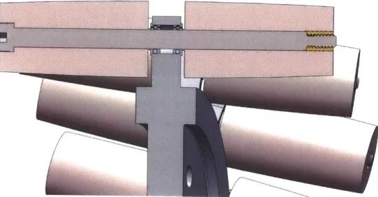
In order to have the wheel behave as close as possible to our model, we must ensure that the rollers spin freely and without substantial friction. At the same time, they must be held in place with no room for wiggle. Figure 3-2 below shows a cross section of one of the rollers that demonstrates how we achieved this requirement. Two roller halves are held to the hub post and to each other using a shoulder screw which threads into a brass insert on the other side. The shoulder screw passes through two flanged bearings inside the hub post. These bearings are held in place by the clamping force of the screw. The roller halves are designed with a small cylindrical indent on the face that meets the bearing. This indent is designed to touch the inner face of the bearing (but not the outer), making it much easier to clamp the roller together (in an effort to reduce wiggle) while not compromising frictionless spin. Of course, if one were to clamp too much, the bearings would be damaged and friction would indeed increase, but this feature makes it much easier to find a stable, low friction assembly.
Figure 3-1: Front view of the 150 mecanum wheel we designed.
Lii
Figure 3-2: Cross section of one of the rollers showing the shoulder screw, flanged bearings, and threaded insert that ensure stability but maintain frictionless spin.
24
0 0 16"
Figure 3-3: Side view of our mecanum wheel design.
For the wheel to spin on the ground without any 'jiggle', there must not be any spaces between the rollers when the wheel is viewed from the side. Jiggle makes it difficult for the speed reduction model and comparisons to a regular wheel to hold. Figure 3-3 below shows our wheel design which indeed very closely resembles a full circle of diameter 6".
3.2
Wheel Prototype
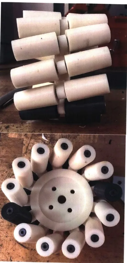
Figure 3-1 on the next page presents our design for a 15" Mecanum wheel.
Figure 3-4: Assembled 15* prototype.
26
Chapter 4
Experiment
To test our speed reduction model on the 15' mecanum wheel, we designed an ex-periment that would allow the wheel to rotate and move in the direction parallel to the roller's axis of rotation. We would then read encoder data on how much the wheel span, read the linear distance is travelled, and compare that to what our model predicts.
4.1
Fixture Design and Build
Figure 4-1 below shows the full CAD design of the testing fixture.
A shaft connects through the center of the wheel to a motor using a flexible
Figure 4-2: Close-up view of wheel and motor assembly.
coupling. The coupling allows for the slight deformation in the shaft from the weight of the wheel. This can be seen more clearly in Figure 4-2. Three vertical plates hold the motor and the shaft, with flanged bearings allowing it to rotate. At the end of the shaft and past the third plate a magnet is attached onto a 3D printed part inserted into the shaft. This magnet spins with the shaft and is detected by the magnetic encoder board which mounts from the vertical board. This board reads out the motor's position.
This wheel and motor assembly is connected to a linear bearing traveling through a meter long shaft. The shaft is held in place by two posts in each end. It's important to not that the wheel is connected at an angle with respect to the linear bearing. That is done so that roller hitting the ground is parallel to the motion of the bearing, and the wheel is free to move in the direction it can move. This is shown clearly in the bottom view of the CAD in Figure 4-6
The fixture was mostly cut on a waterjet, with a few mounts and brackets 3D printed and lasercut. The pictures below show the built fixture ready for testing. It sits atop a soft mat that is there to provide some compliancy and traction.
Figure 4-3: Bottom view of fixture.
Figure 4-5: Top view of fixture.
Figure 4-6: Close-up of motor wheel assembly .
Regular Wheel Distance (in) Wheel Distance Measured (in) Wheel Model Distance (in) 55.89 11.90 14.47 55.89 11.88 14.47 55.89 11.69 14.47 55.89 11.38 14.47 55.89 11.25 14.47 55.89 11.10 14.47 55.89 11.43 14.47 55.89 11.75 14.47 55.89 11.10 14.47 55.89 11.38 14.47 Average: 11.49 14.47 Uncertainty: 0.10
Speed Reduction Ratio: 1:4.9 1:3.9
Table 4.1: Results of the 15'mecanum wheel with a measured diameter of 5.93" running 3 revolutions.
4.2
Results
The wheel was allowed to spin for exactly 3 revolutions, then the linear distance travelled by the bearing was measured and noted down. This was repeated 10 times. The real diameter of the wheel prototype was measured to be 5.93" and that is what's used is calculating the model distance. Table 4.1 below displays the results.
The average nominal linear distance was found to be 11.49", as compared to the model distance of 14.47". That makes for an error of 20.6%, meaning our wheel's speed was reduced by 20.6% more than expected.
The next section addresses the potential reasons our measured reduction is far from our modeled reduction.
Chapter 5
Conclusion and Recommendations
for Future Work
5.1
Experiment Critique and Recommendations
The speed reduction measured in our experiment was 20% higher than expected. This could have happened because our model does not account for slippage or other losses due to friction in the system. There is also still a considerable amount of jiggle in the wheel, as well as not enough compliancy from the mat on the surface. Lastly, measuring tape was used to notate the linear distance travelled by the bearing, which adds a lot of uncertainty to the results.
For future work regarding the speed reduction testing of a wheel of this nature we would suggest accounting for slippage in the model, considering a wheel with a parallel setup of rollers as shown in Figure 5-1 below, as well as molding the rollers with rubber or adding better traction to the mat. We also recommend tracting the linear distance using an overhead camera or lidar sensors that would more accurately read position.
There is a lot of exciting potential for a custom angle mecanum wheel, but firstly, to fully prove the effective gearing it exhibits one must test the torque increase along with the speed reduction.
Figure 5-1: Mecanum wheel with a parallel roller set-up that would reduce jiggle. [3]
(and responsively) change the angle of its rollers with a change in its torque-speed requirement. This presents a big challenge since as the angle changes, the rollers need to get longer to prevent jiggle.
5.2
Conclusion
In conclusion, we analyzed, designed, built and tested a custom angle mecanum wheel for speed reduction. Our results came at a 1:4.9 gear ratio as opposed to the predicted ratio of 1:3.9.
Bibliography
[1] 203mm stainless steel mecanum wheel right with rubber rollers. 14150-Nexus Robot.
[2] 60mm double aluminium omni wheel. Active Robots.
[3] Milliarium consulting. The Mecanum Wheel - Milliarium Consulting.
[4]
Vectoring robots with omni or mecanum wheels. Omni Wheeled Robots - Robots with Omni Wheels Mecanum Wheels.[5] Geometry and kinematics of the mecanum wheel. Graz University of Technology, Institute of Geometry, Kopernikusgasse 24, 8010 Graz, Austria, 2008.
[6] History of wheels and its role in human evolution. Stories of World, April 2016. [7] BLUMRICH. Omnidirectional wheel. US3789947, February 1974.
[8] ILON BENGT ERLAND. Wheels for a course stable selfpropelling vehicle
mov-able in any desired direction on the ground or some other base. US3876255, April
1975.
![Figure 1-1: The wheel throughout centuries. Only minor changes with basic design concept the same.[6]](https://thumb-eu.123doks.com/thumbv2/123doknet/14003673.456167/13.917.206.687.723.850/figure-wheel-centuries-minor-changes-basic-design-concept.webp)


![Figure 2-1: Illustration of traction on a mecanum wheel[1]. The non-perpendicularity of the rollers reduces its speed.](https://thumb-eu.123doks.com/thumbv2/123doknet/14003673.456167/17.917.272.595.603.874/figure-illustration-traction-mecanum-wheel-perpendicularity-rollers-reduces.webp)
![Figure 2-2: Three-Mecanum-wheeled vehicle used for kinematic analysis. [5]](https://thumb-eu.123doks.com/thumbv2/123doknet/14003673.456167/18.917.356.604.107.376/figure-mecanum-wheeled-vehicle-used-kinematic-analysis.webp)
![Figure 2-3: Diagram illustrating parameters in kinematic model[4]](https://thumb-eu.123doks.com/thumbv2/123doknet/14003673.456167/19.917.244.625.119.469/figure-diagram-illustrating-parameters-in-kinematic-model.webp)