DISORDERING KINETICS IN ORTHOPYROXENES by
James R. Besancon
B. S., Yale University (1969)
Submitted in partial fulfillment of the requirements for the
Degree of Doctor of Philosophy
at the
Massachusetts Institute of Technology May 12, 1975
Signature of Author.
...---...---.---Dept. of Earth and Planetary Sciences
Certified b...-...--..--Thesis Supervisor
WITN
MI RA 0 / F1/DISORDERING KINETICS IN ORTHOPYROXENES
by
James Robert Besancon
Submitted to the Department of Earth and Planetary Sciences in May 1975, in partial fulfillment of the
requirements for the degree of Doctor-of Philosophy ABSTRACT
Isothermal heating of a quasibinary orthopyroxene, Mg1.70Fe.2 6Ca.0 2Al.0 45i1 .9 606 resulted in increasing
Fe - Mg2+ disorder, which was measured by Mossbauer spectroscopy. Several pieces of equipment were designed for this study, including a multiple-sample, independent quenching, electric furnace, with oxygen fugacity
control-led by gaseous buffering mixtures, and a vibration-damping table for the Mossbauer spectrometer.
Minimum values of equilibrium disorder are higher than predicted by ideal solution models. The Saxena-Ghose (1971) model is applied to existing disorder data at 7000C
and 8000C, and activity coefficients calculated by least
squares fitting. Energy parameters for the model are
found to be WM1 = 2.3 kcal, and WM2 = 2.0 kcal. At 8000C, ln K = -.98 and at 700 0C, ln K = -1.24. Because the energy parameters are almost independent of temperature, the
excess entropy of mixing is small.
The progress of disordering with time didnot follow traditional rate equations, or any two-step models; the rate fell more quickly. A modification is proposed to
Mueller's (1969) model, incorporating activity coefficients, showing explicitly the dependence of rate on difference
in chemical potential. At 7500C and 8000C, disordering
passed through a maximum and decreased slowly, suggesting a competing process. A hypothesis is advanced that
dissolution of shear-induced lamellae of clinopyroxene may be the cause of the maximum, and possibly of the
declining rate at 7000C.
A comprehensive defect model for orthopyroxene is proposed, which may be used as a framework to understand transport processes and other phenomena. The dependence of defect concentration on oxygen fugacity is shown.
Increase in oxygen fugacity results in an increase in rate of disordering, pointing to cation vacancies as the import-ant species involved.
Application may be made to rapid natural processes, such as cooling rates of volcanic rocks and emplacement of kimberlites. Preliminary data suggest, that kimberlite was very rapidly quenched from high temperatures.
An appendix discusses factors affecting the intensity of Mossbauer peaks.
Thesis Supervisor Roger G. Burns
TABLE OF CONTENTS
Chapter 1 - Introduction p.9
Chapter 2 - Experimental Design p. 14
Chapter 3 - Mossbauer Spectrum Methodology p.46
Chapter 4 - Disordering Data p.58
Chapter 5 - Discussion of Equilibrium Distributions p.68
Chapter 6 - Defect Equilibrium and Disordering p.73
Chapter 7 - Isothermal Disordering with Time p.90
Chapter 8 - Applications of Order-Disorder in
Orthopyroxenes to Natural Processes p.106
Appendix A p.111
Appendix B p,113
5
TABLES
1 p. 16 Microprobe analyses of pyroxene and chromite inclusion. 2 p. 28 Typical flow rate data for capillaries.
3 p. 54-55 Disordering data
4 p. 71 Parameters from least squares fit of distribution data to Saxena-Ghose model.
5 p. 83-84 Variation of native imperfections under varying neutrality
FIGURES 1 p. 23 Gas mixing apparatus
2 p. 29 Bunsen bubble tower for gas flow measurements 3 p. 32 Quenching furnace, schematic
4 p. 33 Gas inlet system for furnace 5 p. 38 Samples attached to furnace head 6 p. 40 Furnace head joint
7 p. 49 Mossbauer spectrometer support table
8 p. 57 Representative Mossbauer spectra 9 p. 59 Disorder vs. time, 7000C
10 p. 60 Disorder vs. time, 7500c 11 p. 61 Disorder vs. time, 8000C
12 p. 62 Disorder vs. time, 7000C, semilogarithmic plot
13 p. 87 Variation of native imperfections with R.
14 p. 97 Model calculation of disorder vs. time, 7000C
15 p. 98 Model calculation of disorder vs. time, 8000C 16 p.101 Sketch of pyroxene octahedral chain
The heavens themselves, the planets, and this centre Observe degree, priority, and place,
Insistiture, course, proportion, season, form, Office, and custom, in all line of order. .
W. Shakespeare, Troilus and Cressida
I. iii.
I know a planet where there is a certain red-faced gentleman. he has never looked at a star. He has never loved any one. He
has never done anything in his life but add up figures. And all day he says over and over, just like you: 'I am busy with matters of consequencel' And that makes him swell up with pride. But he is not a man - he is a mushrooml
ACKN0dLEDGEMENTS
Financial support for this thesis came from the Department of Earth and Planetary Sciences, which funded much of the equipment expenditures. Professor R. G. Burns also provided significant material aid.
Personal support came from teaching and research assistantships at MIT, from a Sloan fellowship, from New England Nuclear Corp., and from
the University of Rhode Island.
Technical help and discussions with the following people were an invaluable aid in the completion of this thesis:
Dr. A. Duba, Dr. E. Whipple, Prof. N. Gray, Prof. S. Hafner, Dr. F. Huggins, Dr. R. Abu-Eid, Mr. K. Goettel, Mr. D. Skibo, Dr. J. Chernosky, Dr. D. Wones, Prof. C. Goetze, Dr. T. McGetchin, Prof. P. Hurley,
Dr. D. Kohlstedt, Prof. W. Pinson, Prof. H. Fairbairn, Prof. F. Frey, Prof. J. Dickey, Prof. D. Vaughan, Prof. J. Tossell, Mr. W. Menke, Mr. C. Sung, and Mrs. V. Burns.
My wife has been an inspiration and help in many ways, too numerous to mention.
Chapter 1 INTRODUCTION
As a result of the solution of the crystal structure of enstatite (Warren and Modell, 1930), it is now known that there are two crystal-lographic sites in orthopyroxene, of different symmetry, which can accept either magnesium or iron. Ghose (1965) confirmed, by x-ray crystal structure refinement, his earlier predictions (Ghose, 1962) that ferrous iron is enriched in the more distorted of the two octa-hedral sites in hypersthene, the site designated M2. This discovery provoked a spate of interest in cation distribution studies as a possi-ble geothermometer, and as a modifier of intercrystalline equilibria involving iron and magnesium exchange with coexisting olivine.
Interest in site occupancies led to attempts to find better ways of measuring the site populations of orthopyroxenes, the x-ray diffraction method being costly and time consuming. The method showing the most promise was the Mossbauer effect, the resonant absorption of nuclear
gamma rays emitted by an excited state of iron-57 and absorbed by natural-ly occurring iron-57 in the pyroxene (Bancroft et al., 1967; Marzolf et al., 1967; Evans et al., 1967; Ghose and Hafner, 1967). Iron in the two different sites showed different Mossbauer parameters so that separate doublet absorption peaks arose from each site. The relative areas of the respective doublets were assumed to be an accurate measure of the propor-tion of ferrous iron in the two sites, an assumption which was borne out by later studies (Virgo and Hafner, 1970; Burnham et al., 1971).
In addition, the amount of ordering of iron was shown to be temperature dependent (Evans et al., 1967; Ghose et al., 1967).
As a result of these preliminary measurements, a series of experiments was undertaken by Virgo and Hafner to determine the temperature dependence
of the ordering and disordering reactions, and. any effect the rate of exchange might have. In a classic paper, Virgo and Hafner, (1969) ob-tained data and developed a theory of ordering in a number of heated orthopyroxenes which provided a consistent and useful picture of the nature of the ordering reaction and disordering reaction. They also described some preliminary data on the rates of those reactions. A consistent thermodynamic theory, based on work by Mueller (1962, 1967), Matsui and Banno (1965), and Grover and Orville (1969), was presented
that showed an approximately constant energy of exchange between the two sites in the temperature and composition range examined.
Virgo and Hafner (1969) had obtained the rate data on two ortho-pyroxenes, of composition fs .57 and fs .3209, in a series of disordering experiments. The activation energy of the reaction was estimated to be about 20 kcal per gram formula weight, using the kinetic model of
Mueller (1967, 1969). The rate constants determined at 5000 C were about the same for both ordering and disordering, leading to a suspicion on their part that the model was inadequate, but further data were needed to analyse the problem.
Virgo and Hafner (1970) further delineated the cation distributions in naturally occurring orthopyroxenes, and showed that the degree of
ordering corresponded to temperatures that were often lower than would be predicted by independent means such as petrogenesis. Additional studies by Dundon and Hafner (1971) showed that shock treatment of pyroxenes increased the observed disorder. Burnham et al. (1971) in-vestigated the correlation between site population estimates obtained from x-ray crystal structure refinements and Mossbauer spectroscopy, and found quite good agreement between the two methods. They also investigated the thermal vibrations in the pyroxenes examined.
Saxena and Ghose (1971) repeated some of the experiments of Virgo and Hafner, and presented a thermodynamic model based on the work of Guggenheim on regular solutions. Their results were in general agree-ment with those of Virgo and Hafner, but their model took into account the nonideality of the solution. This work was elaborated on by Saxena (1973), who reviewed the relevant aspects of Guggenheim's theory.
A somewhat different approach was taken by Navrotsky (1971), who calculated the configurational entropy using methods of statistical mechanics. She showed that the solution, at least so far as the data of
Virgo and Hafner, could be understood in terms of simple ideal solution, the negative enthalpy of mixing being offset by a negative entropy
of mixing. The calculation of the configurational entropy is similar to that of Brown (1971), who derived the general equation for entropy in ordered plagioclase , but not pyroxene.
Much work on the kinetics of the ordering and disordering processes in minerals is contained in the papers of Mueller (1967, 1969, 1970),
who modified the theory of Dienes (1955). The assumption made is that the ordering rate follows Fick's laws of diffusion, the rate being depen-dent on the degree of order (or disorder
)
already achieved by the system. A theory developed by Vineyard (1956) used a set of distribution functions to describe the array of atoms in various configurations, and was able to show the time dependence of long range order in nonequilibrium situations. This theory converges to the results of Bragg and Williams (1934) and Dienes (1955) at equilibruim. Another virtue of the Vineyard theory is that it is able to discuss diffusion by either direct interchange mechanisms (physically unlikely) and vacancy mechanisms ( a possible mechanism in pyroxenes). The major problem of the Vineyard theory is that it is difficult to apply to complex crystal structures, and differ-ential equations arising from it are difficult to solve. As discussed by Mueller for the case of Dienes' model, the usual metallurgical assump-tion that the energy term in ordering depends on the degree of ordering is probably invalid for the case of oryhopyroxenes, because the silicate framework (and therefore the anions) remains essentially fixed no matter what the degree of ordering. The energy per interchange of Mg and Fe between M1 and 142 sites is probably fixed by the geometry of the sites, and is little affected by the nearest cations which are really second nearest neighbor atoms. This assumption can simplify significantly the Vineyard theory.The most recent useful work on ordering and disordering rates in orthopyroxenes is the work of Gray (1974), who used a geometric model
based on the work of Vineyard. His theory is able to predict the direc-tion of variadirec-tion of rates from the equilibrium, Dienes - Mueller type, models. Unfortunately, it can not be applied quantitatively to experi-mental results because the parameter used in the calculation is based on
physical and geometrical theory and can not be measured directly by either x-ray diffraction or Mossbauer techniques. It is related to non-equilibrium distributions on a microscopic scale.
Further work of some relevance to ordering rates in pyroxenes was done by a number of workers on feldspar ordering, which shows some quali-tative similarities to the orthopyroxene case. The ordering examined here is Si - Al ordering in tetrahedral sites. Holm and Kleppa (1968) showed that the rate can be described as a two-step process in albite, with final equilibrium taking much longer (40+ days at 10000C) than the faster initial equilibrium. An important paper applicable to the present thesis is that of Smith and Ribbe (1969), who discussed ordering in plagioclase feldspars, an ordering process that is strongly affected by the presence of domain structure and structural changes across the
compositional range of the feldspars.
The present study was initiated in order to investigate in more detail the kinetics of disordering reactions in orthopyroxenes. Evalu-ation of rate controlling factors was the major goal.
Chapter 2 EXPERIMENTAL DESIGN
Because ordering reactions in general seem to be controlled by diffusion rates of the relevant atomic species between crystal sites, the normal factors controlling diffusion were considered. They are temperature, pressure, major element composition, trace element content, structure, surface area, and partial pressure of both the major elements and possible catalysts like hydrogen. As all of these factors could not be fully investigated in one thesis, the ones thought to be most important have been examined: temperature, and partial pressures of major and possibly catalytic atoms.
The major element composition factor is examined only indirectly,
by comparing with the results of Virgo and Hafner, (1969), and Khristo-forov et al., (1974). The effect of pressure, while relevant, was experi-mentally intractable if oxygen fugacity was also to be controlled. Trace
element content was entirely too complex for kinetic analysis, even in supposedly "pure" synthetic pyroxenes and usually does not alter the basic mechanisms of diffusion of major ions.
For imperfections in the lattice caused by "foreign" ions, the num-ber of impurity atoms is larger than the numnum-ber of solvent atoms dis-turbed by the surfaces present (in macroscopic crystals) until the im-purity level reaches one part in 108 or less (Flynn, 1972). Thus surface effects (surfaces are usually high diffusion rate paths) are much more important than impurities for most processes that occur in even the
purest synthetic minerals. Sample preparation minimized surface area produced by crushing and grinding, and the sample was homogeneous in size distribution, but surface area was not measured as an independent vari-able.
The experimental design was chosen with these factors in mind. In order to make the system as simple as possible, the first major decision involved choice of sample. Ideally, it should lie in the binary system MgSiO3-FeSiO3, with little substitution of calcium, mahganese, titanium, or aluminum. In order to keep the compositional factors as constant as possible, enough sample was required to perform all the heating experiments on homogeneous, sized splits from one original sample. In addition, it was desired that the composition lie in the bronzite range, making it similar to some pyroxenes obtained from kimberlite xenoliths. In this way, the data could perhaps be applied to models of kimberlite emplacement (McGetchin and Ullrich, Iq 73 ), which call for rapid cooling by adiabatic expansion.
Such a sample was located in the M.I. T. collection after a screening by optical and atomic absorption analysis of several samples. The
ortho-pyroxene is an almost completely monomineralic specimen from harford County, Maryland, hereafter designated HCo. Electron microprobe analysis
(Table 1) verified the quasibinary nature of the sample, the absence of zoning, and almost complete absence of macroscopic clinopyroxene exsolu-tion lamellae. Optically, the sample is homogeneous except for a very few exsolution lamellae, very tiny blebs of chromium iron spinel (analysis,
Table 1 Microprobe Analyses Sample HCo: Wt.Percent 0.59 0.11 0.02 32.42 1.07 -55.65 0.41 0.22 8.74 99.22
Cation (basis
6
oxygens) 0.021 0.002 0.001 1.702 0.043 1.960 0.011 0.006 0.257 4-.004 Opaque inclusion in HCo (Chromuite)Oxide Wt.Percent Cation (basis 4 oxygens)
Cao 0.00 0.000 Tio 1.16 0.039 Na2 0.00 0.000 Mgo 1.43 0.096 Al0 3 0.94 0.049
Si2
0.40 0.017 Cr203 23.76 0.852 MnQ 0.47 0.017 Feo 2.412 91.70 3.481(Above analysis then recalculated, proportioning iron between ferric and ferrous componentsi
(Fe 2+Mg.)(Fe (1.9 1M .09~ 12 Cr7 7Al.04)04)0 Oxide CaO TiO 2 Na20 mg6 Al 0 SjiS 3
Cr
S3
Mn6 FeC17
Table 1), and a number of shear planes. The calcium content of the sample as measured by atomic absorption agreed quite clobsely with the value obtained by electron microprobe, suggesting that the sample contains most of the calcium within the orthopyroxene phase rather than in the very minor exsolved clinopyroxene.
Examination of sample HCo by transmission electron microscopy showed many planar features superimposed on the regular 14A spacing of the (100)
planes. These are interpreted as shear features resulting from solid state deformation of the pyroxene. The exact nature of structures such as these has been debated in the literature; they have been interpreted both as stacking faults and as small included areas of clinopyroxene.
Buseck and Iijima (1974) have fairly strong evidence that the latter is sometimes true. They interpret the planar features observed in the Norton County enstatite as clinopyraxene induced by the shock that pro-duced the observed brecciation. This agrees with the findings of Turner, Heard and Griggs (1960), who reported the stress induced transition from orthoenstatite to clinoenstatite. No quantitative measure of the abun-dance of these shear features was made, but their volumetric significance is relatively low. During experimentation, temperatures were kept low enough that protoenstatite should not have appeared, because on quench-ing it would have produced significant quantities of clinoenstatite. However, the temperatures used should have annealed much of the clino-enstatite and converted it to orthoclino-enstatite, which is the thermodynamic-ally stable phase in this temperature range. This annealing has been
observed by Boland et al. (1974), during experimentation on the electrical conductivity of orthopyroxene, and will be discussed with the results of the present thesis.
The symmetry of the sample obtained was assumed to be orthorhombic, but no crystal structure analysis was attempted. In order that the field
of stability of orthopyroxene not be exceeded, the temperature of all experiments was kept below 10000C, as the effect of a gross structural rearrangement would almost certainly alter the disordering process. The stability field of orthopyroxenes in that region has been investigated by Smyth (1971). Other information of the structure and stability of
orthopyroxenes can be found in Smith (1969), Smyth (1969), Smyth (1970). Smyth and Burnham (1972), Smyth (1973), and Nitsan (1974).
A natural mineral was chosen for the experiments rather than a synthetic one because of the ready availability of large quantities of homogeneous material produced under essentially identical conditions, particularly an identical temperature history. The presence of small amounts of elements not present in the pure binary system was of some-what less importance than other factors. A further advantage in using a natural mineral derived from a metamorphic environment is that
exten-sive ordering over a long time period had taken place, a situation not easily achievable in the laboratory for a synthetic sample of rela-tively large size. The highly ordered natural sample made the changes in degree or ordering on heating larger than would be possible for a more disordered, laboratory produced sample. This ensured that the
high-19
est possible precision in measurement would be achieved.
The control of the partial pressure of major ions and catalytic ions is a major advance in the study of ordering kinetics of ortho-pyroxenes. As mentioned above, it is thought that possible mechanisms responsible for diffusion (and rearrangements like ordering) are the movement of vacancies or of interstitial atoms through the structure. It should be possible to verify the machanism as resulting either from vacancy diffusion or by interstitial movement, by measuring the effect
of increasing or decreasing the number of vacancies present. As will be discussed in a later section, this number of vacancies can be con-trolled by the activity of either the cation or anion in the environ-ment around the crystals.
The factors described in chapter 1 necessitated the design of apparatus for heating samples to the required temperatures. Other
re-quirements included long term temperature stability, maximum precision in sample treatment, rapid quenching, and long term oxygen fugacity control. Economy of construction was also a major factor in design, as the budget for equipment was quite low.
At first, solid phase oxygen buffers were considered, which con-sisted of mixtures of metal and metal oxides that control the fugacity to a calculable value at a given temperature. Because of the limited variability of the system, and the added complication of using a double
capsule, this was finally rejected. Another factor legislating against this type of system is that reliance must be made on hydrothermal
appar-atus instead of a simpler furnace arrangement. The optimum arrangement then seemed to be buffering using gas mixing, with systems such as CO -C02 or H2 - C02*
The basic idea of using gas mixtures like these is that high temper-ature dissociation of the gases (or their reaction products like H20) releases a very small amount of oxygen, which is available to react with
solids present. Assuming that equilibrium with the solid is achieved, partial pressure of oxygen in the solid is controlled. In the present case, the CO2 - H2 mix was used as the basic mix because of the low cost of these gases relative to CO (about $50 for a cylinder containing 200 cubic feet). The equations necessary for calculating the equilibrium in this system are found in Muan and Osborn (1965) and in Nafziger et al.,
(1971), and will only be outlined here.
The method consists of using tabulated thermodynamic data for the free energy of formation of the gases involved, and calculating the equilibrium constants for the possible reactions between them. These equilibrium constants can then be related by the stoichiometry of the reactions to the partial pressure of oxygen. The important equations for the H2 - CO2 system are:
(1)
C2
=
CO +
i
02
and
(2) H20 = H2 + 10
2 *
The equilibrium constants for these equations are, respectively,
f f
(3) Ki CO 0 and
21
f f 2
(4) K2= H2 02
f
H20
Assuming the fugacity is equivalent to the partial pressure of these gases in a mixture at one atmosphere, and that the sum of the partial pressures of the gases CO, H20, CO 2, and H2 is unity at one atmosphere (ignoring other possible species like CH4, French (1966)), one can write the equations pCO2 PC02(i) I + PC+ (5) pC2() O pH2(i) 1 -+ pH20
where i denotes the initial quantities of each gas. This can then be recast ass 1 f 1 + f2 T (6) 002(i) 1+K 2 K2 fH2(i) 1+ K2 f2
A simple Fortran IV program was written to provide tabulated values of the volume percent CO2 in a mixture of H2 and CO2 that would produce a given oxygen fugacity at a given temperature. The program (Appendix A) uses equation 6, assuming that the values of free energy of formation of the gases involved can be linearly extrapolated for temperatures between the 100%X values given in most compilations, an approximation that is overshadowed by other errors in the experimental setup. Any
consistent set of free energies can be plugged into the data section of the program, such as that of Coughlin (1954) or Elliott and Gleiser (1960). However, the set used (differing very little from the above two) is taken from Robie and Waldbaum (1968). Equilibrium constants follow from AG=-RTlnK, where AG is the difference in free energies, and K the equilibrium constant. A better set of tables for both H2 - CO2 and CO - CO2 has recently become available (Deines et al., 1974), and these are used in this thesis.
The next concern in experimental design was to achieve accurate delivery of a stream of gases mixed in precisely the ratio desired with reasonable long term stability and reproducibility. The design chosen for a gas mixer is based on that of Darken and Gurry (1945), as modified and described by Nafziger et al.(1971). The important feature is that
the gases are applied at a constant pressure against one end of a capill-ary, and the resulting flow rate through the capillary is proportional
to the applied pressure, and is linearly proportional within some experi-mentally useful range. By setting the pressure drop across a capillary
to some predetermined value and allowing any excess gas to bleed off, a constant and continuously adjustable flow can be achieved through the capillary. By setting up a separate capillary for each gas, the ratio of the two can be varied within the limits set by the linear flow regime of the capillaries.
A schematic diagram of the gas mixer is illustrated in Figure 1. The pressure drop across the capillaries is monitored by U-tube
mano-Figure 1 Gas mixing apparatus. System is symmetrical, with light colored central tube being the mixing tube, then the manometers, then the overflow bubble tubes.
meters, which are calibrated against flow rate, as described below. An inexpensive and convenient fluid for indicator liquid is high grade vacuum pump oil, which has an extremely low partial pressure, is chemi-cally stable, and has a low density which makes possible use of relative-ly larger and stronger capillaries because the required pressures are low. If mercury were used as manometer liquid, extremely fine capill-aries would be needed to provide the relatively low flow rates used in the experiment.
The gases are combined in a one inch tube packed with glass wool for thorough mixing. The resultant mixture is led out through high vacuum rubber tubing to minimize differential diffusion, which might alter the mixing ratio of the two gases.
Excess pressure of each gas is applied to the system, but this is reduced by the needle valve on the gas cylinders and by a bubbler. This consists of two concentric glass tubes, with the outer tube filled to an adjustable level (set be raising or lowering an external reser-voir) with pump oil. Gas flowing into the inner tube forces the oil out until gas is bubbling up through the oil in the outer one. At this
point, the pressure of gas in the inner tube is relatively insensitive to fluctuations in the applied pressure, as any excess gas simply results in an increase in bubbling rate, and a paucity of gas results only in a decrease in bubbling. This then is the constant pressure which is applied to the capillary.
con-25
struction can be made by simply interconnecting standard glass parts with small sections of Tygon tubing. Some care must be exercised in use of Tygon, as CO2 diffuses through it even though it is impervious to hydrogen, the rate being dependent on wall thickness and length of tubing (Nafziger et al., 1971). If the amount of tubing is kept to a minimum and is in place during calibration of the apparatus, there
should be no real problem.
Capillaries are usually custom constructed for use in the apparatus by drawing out commercial heavy walled capillary tubing to smaller dia-meters. If the constriction of the tube is carefully done, the resultant flow rate - pressure relationship is linear over a larger range of
pressures, and the capillary is correspondingly more useful. Constric-tions of about -! millimeter proved to be the correct range, but trial and error is the only way for deciding on the utility of any individual
capillary made. Fancier constructions, which allow easier interchange of capillaries than simple Tygon connections, can be made if a glass-blower is available. Designs for some of these capillary systems are shown in Nafziger et al. (1971).
Stopcocks or screw clamps can be added in several places to facil-itate the setup of a given flow rate. These include one between each reservoir for the bubbler fluid and the bubbler itself to keep the fluid level constant, and two more which isolate the two sides of the mixer from each other to aid in calibration.
bubbling rate is slow and steady, and the pressure is read off a scale set by the manometer. To increase the flow rate, the bubbler reservoir is raised and the level of fluid in the bubbler is increased, creating a higher head pressure. The flow into the system is then increased -until the slow bubbling rate is again achieved. By manipulation of the
reservoir fluid, the pressure can thus be set to any value of the manometer.
With capillaries in the 4 millimeter range, the requisite flow rate of 0 to 4 cm3/sec was easily achieved with bubbler tubes about one meter long, and resulting differential pressures on the manometer of about
50 cm of pump oil.
The entire mixer was mounted on a board which was firmly attached to a wall. The glass was attached by standard laboratory clamps (kindly provided by Prof. P.M. Hurley) to metal rod frames which were set about four inches from the board. Some way must be provided to get access to the capillaries at the top of the system so that they may be changed. Care must be taken when changing capillaries not to restrict signifi-cantly the Tygon tubing, otherwise the flow regime may either lose calibration or simply always be nonlinear.
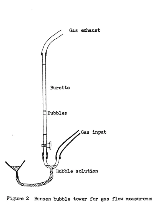
Calibration is accomplished with a Bunsen bubble tower. This consists of a broken burette, the fine tip being completely removed. Gas is
led into one arm of a Y shaped tube at the bottom, and allowed to pass through the other arm of the tube and then up the burette. Soap bubble solution (several preparations were tried but commercial children's
bubble solutions proved to be the best) is introduced through the base of the Y. The level of solution is raised until one or several bubbles are produced and begin to rise through the burette. The time required for a given volume of gas (typically about 50cm3) to rise was measured with a stopwatch. Ten duplicate runs (or five in the case of unusually
low flow rates) were made at each calibration flow rate for each gas and each capillary used. Some capillaries proved to have nonlinear flow rate - pressure relationships and were not used; others proved to be quite suitable. Flow rate data points for about five or more pressures were measured on each capillary that was finally used, and fitted by
a least squares fitting routine to a straight line function, which was then used during setup to find the pressure required for a specified flow rate. Deviations from linearity were checked by graphical analysis of the data, which showed the linear portions of the flow regime. The flow rate data for the capillaries used are summarized in Table 2. Figure 2 is a schematic diagram of the bubble tower.
The optimum flow rate for gas mixing furnaces which minimized thermal diffusion (causing unmixing of the gases) and temperature un-certainties was obtained from Darken and Gurry (1945). For a one inch furnace tube (such as that used in this study) and a twelve inch long heated zone, the optimum flow rate is 0.9 cm/sec through the tube, or a total flow of 4 cm3/sec. This total flow rate was used in all experi-ments, proportioned between the two gases.
Table 2
Typical flow rate data for capillaries
C02, Capillary Al, left side of mixer. Manometer Pressure (cm oil) F
36.35 31.85 48.15 23.95 19.10 15.00 32.75 44.15
H2, Capillary A2, right side of mixer. Manometer pressure (cm oil)
14.45 20.60 31.00 41.90 19.00 13.50 8.90 3.75 1.65
low rate (cm /sec)
1.525 1.333 1.973 0.978 0.781 0.637 1.312 1.768
Flow rate (cm /sec) 1.020 1.459 2.222 3.014 1.359 0.942 0.621 0.249 0.101
Gas exhaust
Burette
Bubbles
Gas input
Bubble solution
Figure 2 Bunsen bubble tower for gas flow measurements
into the mixer. Hydrogen is normally just dried by passing through a tube packed with Drierite (CaSO4 to which an indicator is added that shows when the drying capacity is expended). CO2 is oxidized to
eli-minate any hydrocarbons or carbon monoxide. Previous investigators have used heated copper gauze and activated A10 3 with Drierite to re-move water. At the suggestion of Earle Whipple, this system was replaced
by one in which CO2 was bubbled through a chromic acid cleaning solution (made by adding potassium dichromate crystals to concentrated sulfuric acid) which very effectively both oxidizes and dries the gas. As a
precaution to remove the cleaning solution, the gas was then passed through a Drierite tube. This system was shown by Whipple to result in improved chemical purity for the C02, as demonstrated by lessened reducing power when used as covering gas during ferrous iron
determina-tions (Whipple, 1973). Carbon monoxide was cleaned with sodium hydroxide pellets, which both dry the CO and remove CO2'
From the gas mixer, the gases are led into the furnace system. This was designed with economy in mind, as well as maximum utility and reproducibility of results. The most important features of the furnace design were: the ability to run seven samples at a time, with temper-ature measured at all times in a symmetrically equivalent site in the furnace; complete sealing against contamination of air; cooling of exit gases to allow venting into a hood duct; and independent rapid quenching
of each sample. The advantages of running multiple samples are great: all samples in the run experience the same conditions of temperature
and oxygen fugacity; as well as the same temperature history during initiation of a run; and great economy is achieved in equipment usage and time.
An electrically heated furnace mounted in a vertical position was used. It was cylindrical, wound with Kanthal wire, and had an 18 inch heated zone. The length of the heated zone was probably a positive factor in promoting equilibration of the gases in the mix before they reached the sample area. The opening in the ceramically lined tube was
about 1- inches in diameter. Inside this, a tube of fused silica was * placed, which was the actual furnace tube. The 1" diameter silica tube
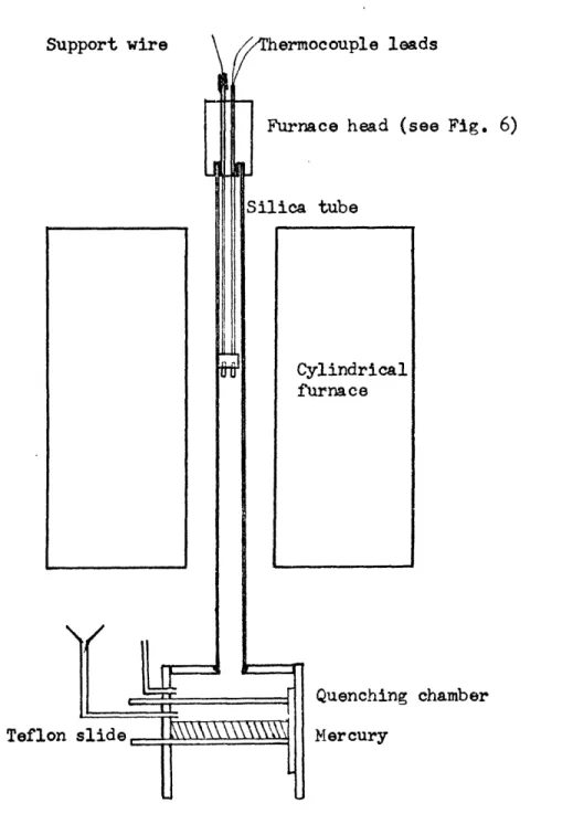
projected about one foot from each end of the furnace, and allowed the connections of gas and sample support to be somewhat insulated from the furnace area and maintained at a reasonable low temperature (Figure 3). Silica was chosen because of its good radiative thermal conductivity and becauses it contributes negligible contamination to the sample. A
ceramic tube could easily be used instead. The vertical configuration was best because it allowed the simplest quenching of samples.
The gas inlet system (Figure 4) was designed as a two gate valve airlock, so that samples could be removed from the furnace without-allowing contamination of the gas stream by air, which would not only upset the gas buffering but might be dangerous in the presence of hydro-gen. The original plan was to use liquid nitrogen as a quenching fluid, because it would be essentially inert in the system and would not have the toxicity problems associated with mercury, the traditional quenching
Support wire hermocouple leads
Furnace head (see Fig. 6)
Silica tube
Cylindrical furnace
Quenching chamber
Teflon slide Mercury
Figure 4 Gas inlet system. White plastic gastight slides visible at left. Furnace tube is held in upper
fluid. Problems which developed after construction showed that liquid nitrogen could not be used, however, because it would not flow freely enough through the inlet system into the quenching chamber under the influence of gravity alone, so the liquid nitrogen technique was aban-doned. The system proved to be quite suitable for use with mercury, however, so that was used as quenching fluid. An enlarged fluid inlet might allow nitrogen to be used. The mercury was kindly provided by Professor P.M. Hurley.
Figure 4 is a photograph of the quenching chamber. It is an in-verted open box of Plexiglas with a rabbeted hole in the top for the furnace tube. Two slots were cut into the box horizontally, into which were fitted Teflon sheets, so that they slid in and out like drawers. The sheets were long enough to protrude from one side of the box and fit into the slots in the side. They were supported at the edges by slots in the side walls of the box, and butted (when slid all the way in) against a piece of foam rubber glued to the rear wall of the box. When in place and properly covered with high vacuum grease (siliconetype),
they were perfectly gas tight. The gas mixture was introduced through a joint in the section of the box above both slides. If either was closed, the gas flowed freely through the upper part of the box, out the top hole, and into the furnace tube. Between the two slides was a connection through which mercury was introduced by means of a funnel and flexible tube with pinchcock. If the bottom slide was closed, the mercury collected on the bottom plate.
In operation, mercury was allowed to flow into the chamber with the bottom slide closed until it was half filled, then the mercury supply cut off at the pinchcock. The top slide was pulled out part way, so that the surface of the mercury was exposed to the furnace
opening. A sample being quenched dropped in its capsule into the mercury. During all this time, the system was still gas tight because the upper plate sealed the opening
jto
the air, as did the bottom plate. When the sample was in the mercury (floating on it), the top plate was slid. all the way in, isolating the middle chamber from the gas stream. Then the bottom plate was slid out and the mercury and sample fell into a plastic cup placed under the apparatus. Care was taken to catch all the droplets of mercury, which almost always splashed to some extent. The bottom plate was then closed and fresh mercury introduced into the middle chamber in preparation for the next quench. Mercury vaporsproduced by the quench flowed up through the furnace with the gas mixture and were ported with the already toxic gas mix directly into
the fume hood vent. The apparatus was checked from time to time for the presence of toxic mercury vapors, and any spilled mercury was clean-ed up immclean-ediately. A tray of powdered sulfur below the apparatus pro-vided a surface to collect mercury droplets and also combine with
mercury vapor and lower its concentration in the surrounding air. After the sample was removed from the mercury, it was reintroduced into the funnel and recycled through the system. Any contamination of the mer-cury by particulate matter, such as sample crystals leaked from a
cap-sule, was removed by filtering the mercury through standard filter paper with a pinhole put through the tip, allowing the mercury to flow out. This also provided a convenient way to remove sample capsules from the mercury.
Thus, throughout the entire quench cycle, only an insignificant amount of air (that contained in the volume between the two plates) was allowed into the system, and that is flushed out very quickly.
Samples were quenched separately, and at any time, the length of the run being limited only by the quantity of gases available. With a multiple tank connection manifold, runs could last for extended periods of time.
Samples were contained in platinum capsules made from 3 mm platinum tubes, 1 inch long, open slightly to the furnace atmosphere. At very high temperatures, approaching melting, significant amounts of iron may be lost into the platinum, but at 10000
C
or less, the losses should be insignificant. Other capsule materials may be used, but the high return value of platinum (which could even be reused for experiments where no melting takes place) makes it the material most convenient andeconomical. Silica tubes could also be used if a suitable method can be devised for hanging them on wires, which is the method used to support
the capsules.
Capsules were crimped shut at the bottom, filled with sample, then crimped onto a fine platinum wire by which they were hung in the furnace. The top crimp extended only part way across the opening so that the
capsules were hung by these wires in a position predetermined to be the hot spot of the furnace.
The capsules and wires were kept from touching each other at high temperatures because of the possibility of entangling or actual welding of the parts. This was accomplished first of all by a spacer, (Figure 5) cylindrical in shape, which has cavities in its lower surface into which the capsules were drawn. A smaller hole extended from the top of the cavity through to the upper side, through which the support wire was fed. The spacer was made of Lava "A", a product of the American Lava Corp. which may be readily machined into the required shape, then fired to drive off water and make it strong and stable. Because it is nearly pure Al,03 after firing, it was assumed to have little effect on the samples because of its extremely low vapor pressure. Above the spacer, the wires were sheathed in silica thermocouple tubing to prevent their touching.
The spacer had seven identical cavities (although it could possibly be designed to have more or less) into which capsules could be placed, arranged in a circle. The eighth hole was in a similar position but was enlarged to accomodate a thermocouple, which was constructed so that the junction was in the same position as the middle of a capsule. The two thermocouple wires (which were chromel and alumel in the present study, but could be platinum and platinum-rhodium for higher temperatures) were separated by a small ceramic bead so that there was no electrical junction where they passed through the spacer. Above that, they were
Figure 5 Spacer with sample capsules ready to go into the furnace. Bottom of furnace head joint appears at top. Between are
support and thermocouple wires with silica and ceramic sheathing tubes.
contained in two-hole ceramic thermocouple tubing, which extended all the way up through the top joint of the furnace to the air, where they were connected to a current measuring system.
The top joint of the furnace was designed to be impervious to very hot gas, which passed into it continually from. the furnace. In addition, it had feed-through holes for the various support wires and thermocouple wires, and a channel through which the gas mixture could flow, be cooled,
and vented into the fume hood. It sealed tightly on the furnace tube, just as the bottom joint, to prevent air leaks.
Cooling water circulated through the brass head (Figure 6), which capped the furnace. The top of the furnace tube fitted into a cavity in the head and sealed with an "o"l ring and vacuum grease. The wires for support and the thermocouple were inserted through tubes of brass which extend all the way through the head. The head is hollow, and
cooling water is circulated to cool the wires and gas in the brass tubes. The tubes protruded from the top of the head, and has a short length of rubber tubing slipped over them. The wire came up through
the tube, through the rubber tubing, and out into the air. The rubber tubing acted as a seal when pinched shut with a screw clamp, which also held the wire in place. The tubes through the head were arranged in a pattern identical to the holes in the spacer, except that one extra
tube was provided in the very center through which the gas mix was vented. It was cool enough after passing through the head to be vented from there with ordinary Tygon or rubber tubing.
fns11T
This
rin~anmdgre
T
WmnTo Scale L . piece io be machined 2!
/Pra
m one piece to fit over glass tubeSeve" ites
have this
oection
Bill o ffaterals:
+
Brass tubin
0
,03
ZWaI,
4"',. 4nd
CD
Posiitco of Cross B rass b)ock &"x 14"xr 1 for ring 9reove pieceSection
A
Srass SJhee' , h" iAek for emisiele +nA IIjoin+f Je , soldered wa+er + i9Af
Figure 6 Head joint for furnace.
The spacer was attached firmly to the thermocouple by slipping it down until it wedged against the ceramic bead. The spacer could then be raised or lowered by simply raising or lowering the thermocouple tube, which protruded above the top of the head. In addition, however, the
silica thermocouple tubes which sheath the sample support wires were cut to exactly the correct length between the head and the spacer, maintain-ing it at exactly the correct spot in the furnace. This spot was pre-determined during the calibration of the furnace. When the samples were drawn up tightly to the spacer, the whole system was fairly rigid and
could be slipped down onto the furnace tube fairly readily and clamped into place. The assembled head, with samples, is pictured in Figure 5.
To make a furnace run, the gas mixer was started well ahead of time in order for the oil in the mixer to become saturated with gas and the flow rates to attain calibrated values. The furnace system was assembled and checked for leaks by pinching off the exit tubing moment-arily to see if the pressure in the gas mixer manometers dropped. Leaks were stopped with vacuum grease, which has a very low vapor pressure at room temperature and should not have affected the samples, especially
since the system was being flushed with gas continually. Then the cooling water was turned on and the furnace started.
Temperature inside the furnace was monitored by the thermocouple, which was calibrated against the melting point of gold and of sodium
chloride. This was done inside the furnace in the same position as the thermocouple was to take durinq an actual run.
Temperature control of the furnace, however, was accomplished with a probe inserted between the silica tube and the ceramic furnace tube,
connected to a commercial proportional temperature controller. The setting on the controller, of course, did not correspond .to the thermo-couple in the gas stream, but once set did provide good long term
stability of the temperature inside the tube. In a permanent setup, the controller probe must be mounted so that it does not move. Experi-ence with the furnace built for this study showed that a controlled reproducible temperature could be reached, even after the furnace was shut off, dissembled, reloaded, reassembled, the controller turned on again.
The hot spot of the furnace was determined with the gas flowing at the same rate as during the experiments. The hottest zone was about
2 cm long with a maximum variation of only about I 20C through the zone. The hot spot moved only about 6 mm when the gas flow was stopped.
Temperature readout of the thermocouple was monitored with a Leeds and Northrup potentiometer, which was calibrated to read out in milli-volts the EMF of the thermocouple relative to the EMF of a thermocouple immersed in an ice bath. Temperatures were read from tables provided by Omega, Inc., and were a compilation of the most -recent values of thermal EMF for various thermocouple combinations . The values fdr temperature were corrected in accordance with the melting point deter-minations of gold and sodium chloride. A more convenient setup for temperature readout would involve a modern digital thermometer, which
would also result in reduced cost.
Runs used .150 gm of orthopyroxene, which was previously crushed (maintaining iron free conditions) and sieved to obtain the size fraction between 35 and 42 mesh (~"30 mm). This was placed in the capsule made by crimping one end of the platinum tube, then crimped onto the wire (which was already threaded through all spacers and the head of the furnace). The bottom spacer was supported in place by the thermocouple as noted above. Samples were drawn up into the cavity in the spacer until all were in place,then the head was lowered onto the top of the furnace tube, sealed in place, and the system checked for leaks. The temperature controller was set to the approximate value desired, and
started.
Temperature runup lasted as long as about 45 minutes at 80000. It was assumed (and later verified) that very little change took place
in the degree of order in a sample until a temperature of about 75000 was exceeded, at least in a time scale of minutes. Heating above that
temperature of course did start further disordering in the sample, so the final temperature was achieved as quickly as possible. The first sample was quenched immediately on reaching the final run temperature, in order to evalute any changes that might have taken place.
A second way of correcting for runup time changes in the sample was to change the method of operation slightly. A single capsule with
sample was crimped onto the end of a long wire which had been threaded through the furnace head and the spacers. The sample, instead of being
drawn up into the cavity in the lower spacer, was allowed to hang all the way down into the quenching area of the furnace. After the temper-ature had stabilized at the desired value, the sample was drawn up into
the proper position, held there for the desired length of time (usually a few minutes), and then quenched.
Quenching of either type of run was accomplished by simply un-clamping the wire at the top connection to the furnace head and pulling firmly. The sample capsule would then break free from the wire, or the wire would slip out of the crimp, and the capsule would fall directly down into the mercury below. The stiffness of the spacers permitted
this without disturbing the other samples in the run. This proved
a very satisfactory arrangement. It was simple, economical, and reliable. Only the weight of the sample and capsule was supported by the wire,
the spacers being supported by the thermocouple, so that accidental release of samples was very infrequent.
The furnace proved to give reliable and simple service after con-struction, despite the fact that it was built with economy in mind. Several of the design features proved very helpful in rapid processing
of samples. Quenching of a sample required only a few minutes for the process including a temperature check. During the remaining run time, no maintenance was required except periodic checks to make sure the gas mixer received adequate supplies of gas to insure overflow, and temper-ature checks. The latter may be accomplished with a chart recorder if desired. Another possible improvement in the apnaratus would be to place
45
an oxygen fugacity sensor probe in a sample position, ard record con-tinuously the current flowing through it (Sato, 1971). In this way, complete' records of the operation of the furnace could be kept.
Chapter
3
MOSSBAUER SPECTRUM METHODOLOGYSince its discovery in 1958, the Mossbauer effect (recoilless nuclear gamma ray emission and absorption) has proven a valuable tech-niquo in physics and chemistry, and more recently in geochemistry. The Mossbauer effect was used in this study as a tool to determine the
rela-tive ferrous iron populations of the two similar but not identical crys-tallographic sites in the orthopyroxene structure. Gamma rays were emitted from an excited state of iron 57 which was produced by decay from a prepared source of cobalt
5?.
A certain percentage of the gamma rays emitted resulted in no excitation of vibration in the lattice of the source, and so were emitted with an energy defined precisely by the energy of the nuclear transition itself. This energy was modulated by a Doppler shift, utilizing simple mechanical motion of the source vibrating toward or away from the absorber. In a similar fashion, radiation was resonantly absorbed by iron 57, a component isotope ofnatural iron. A resonant absorption takes place in iron atoms in minerals if the energy of the incoming gamma ray is precisely matched to the energy of the absorbing nucleus. The small energy difference made by the
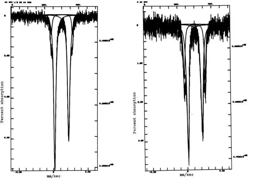
crystalline environment can be compensated for by the Doppler shift induced by the vibrator. When a range of velocities is scanned, the spectrum produced has separate absorption peaks for each iron site. If the peaks do not overlap greatly, the spectrum can be decomposed into
peaks will be a measure of the number of iron atoms in each coordination site.
There are two crystallographic sites for the ferrous iron in ortho-pyroxenes, each giving rise to a doublet absorption peak, or a total of four peaks. These are imperfectly resolved at room temperature, but resolution is much improved at 77K. The sample also must be powdered and the orientation of grains randomized in order to eliminate asymmetry
in the size of the two peaks of each doublet, which could cause problems for the curve fitting routine used to analyse the data, and also give incorrect results.
The major consideration in these experiments was to obtain very
high precision in the measurement of peak areas, as well as high accuracy. With homogeneous sample splits, differing only by their heat treatment and reaction with the buffering gas mixture, It was hoped that other
effects would be cancelled out. The spectrometer, an Austin Science Associates, S3, K3, was set up in the same configuration and samples run at identical temperatures each time. The data were accumulated in a multichannel analyzer with 512 channels, about .008mm/channel, which is more than adequate for resolving any peaks that can be resolved using present techniques. All equipment adjustments were made carefully and then not changed for the duration of the runs. An oscilloscope
was used regularly to check on the operation of the equipment, especially the drive signal feedback, which is the best indication on the spectrome-ter that the equipment is working properly. Room temperature was
main-tained at a constant value as carefully as possible in order to stabi-lize the drive electronics.
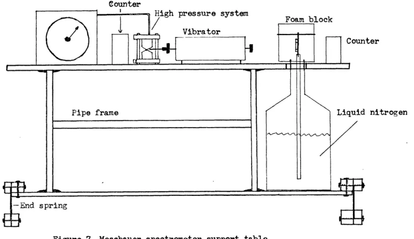
A special table was devised working on the principle of the inverted pendulum and tuned to a very low frequency. It was designed to hold the Mossbauer source drive, the detectors, and associated cryostats and
high pressure equipment, linking them rigidly together but insulating them from spurious building vibrations which could affect the drive, especially in the low velocity regions which lie under some of the
peaks in orthopyroxenes. The principle was derived from a device supplied by Austin Science Associates to insulate the drive and detector for
small samples.
This table is shown diagrammatically in Figure 7. A rigid table, of 3/4" plywood, was built around a steel pipe frame. A platform, also of 3/4" plywood, was provided at a convenient distance below the table top, to hold 25 liter flasks of liquid nitrogen for the cryostat. The top of the table holds the Mossbauer drive, detectors, and high pressure systems. The shelf is in turn supported from underneath by two specially designed feet which run from front to back of the table. The feet
are spring steel sheets, about 4u" wide and run from front to back of the table. They are clamped along the top edge to the shelf of the table, and along the bottom edge to wooden blocks. The center, about 2", is free to bend from side to side. Weight is added to the table until it
oscillates very slowly when pushed sideways and released. This tuning of the oscillation then makes an effective mechanical damping system for
Counter
Counter
Liquid nitrogen
any vibrations of low frequency transmitted through the floor, and will help prevent vibration transmission from the air. Large wedges were
constructed to hold the table steady while changing cryostat flasks. Some previous difficulties with peak intensities in the low velo-city region were improved after installation of the system. Having the entire system linked solidly together also made alignment and ad-justment easier, both for high pressure and for low temperature work. Samples were weighed before being placed in the furnace, and all were .150
t
.002 gm. After quenching, the samples were removed from the capsules directly into a mortar, covered with acetone to prevent oxidation, and ground thoroughly by hand. Sugar was then added in about an equal amount, and the two ground together momentarily. When the acetone had evaporated, the sample was transferred to a sample holder which consisted of a Plaxiglas sheet with a hole 2.2 cm in diameter cutin it. The windows for the transmission of the gamma rays were trans-parent tape, which also held the sample in place. The sample was not compressed but packed loosely so as to minimize any preferred orienta-tion. (See Appendix 2 for a discussion of peak intensity and preferred orientation.) For runs made at the temperature of liquid nitrogen,
the sample was taped to a copper plate which had a hole just large enough to mask the holder but not the sample. This copper plate was connected to a copper rod which hung down into a 25 liter tank of liquid nitrogen. Styrofoam was pushed down over the top of the copper sheet and held in place by a dowel passing through the styrofoam and through a hole in the
copper plate. This thermally insulated the sample. The neck of the nitrogen tank was sealed to the styrofoam with a ring of flexible closed cell foam. To ensure a tight fit, a lead plate was placed on top of the styrofoam to hold it firmly down onto the nitrogen tank. The
sample was then aligned with marks on the styrofoam, and finally by use of a ratemeter on the output of the proportional counter. All of the experiments were run with one source, cobalt 57 in palladium. The
number of counts used for each sample varied, but most were about 600,000 counts per channel, with some as low as 400,000. Each of these figures is quite large, and no great increase in precision could be achieved by increasing the count rate by any reasonable amount. Use of a mod-erately active source (50 mCi) helped limit the time duration of a run and thus minimize drift of the electronics.
The spectra were read out in digital form and processed with the computer program of A.J.Stone, as modified by F.E.Huggins. This fits the known theoretical Lorentzian line shapes to the data, one Lorentzian to each peak specified, with initial constraints on parameters for
economy in fitting time, constraints which may be removed selectively as the fitting routine progresses. Initial estimates of spectrum
parameters must be provided to the program. In order to minimize program induced variation, the same initial estimates, established by carefully fitting one of the spectra obtained, were used for each of the spectra fitted.