HAL Id: hal-01587950
https://hal.laas.fr/hal-01587950
Submitted on 14 Sep 2017
HAL is a multi-disciplinary open access
archive for the deposit and dissemination of
sci-entific research documents, whether they are
pub-lished or not. The documents may come from
teaching and research institutions in France or
abroad, or from public or private research centers.
L’archive ouverte pluridisciplinaire HAL, est
destinée au dépôt et à la diffusion de documents
scientifiques de niveau recherche, publiés ou non,
émanant des établissements d’enseignement et de
recherche français ou étrangers, des laboratoires
publics ou privés.
Coupled Optoelectronic Oscillators
Ramin Khayatzadeh, Vincent Auroux, Gilles Bailly, Arnaud Fernandez,
Olivier Llopis
To cite this version:
Ramin Khayatzadeh, Vincent Auroux, Gilles Bailly, Arnaud Fernandez, Olivier Llopis. Phase Noise
Study Based on Transfer function in Coupled Optoelectronic Oscillators. IEEE International Topical
Meeting on Microwave Photonics, Oct 2017, Beijing, China. 4p. �hal-01587950�
Abstract— In this paper, the transfer function theory is used to model the phase noise power spectral density in coupled optoelectronic oscillators. A resonator is placed into the model in order to take into account the quality factor (Q) enhancement due to the optical loop. The results of this model are then compared with experimental measurement results. The model is able to describe the phase noise spectrum shape and to give indications on the noise contributors, which helps in improving oscillator’s performance.
Keywords—Phase noise, optoelectronic oscillators, quality factor, power spectral density (PSD).
I. INTRODUCTION
The important rise of advanced telecommunication and signal processing systems in the past decades has increased the necessity for high spectral purity microwave and millimeter wave oscillators. Frequency multiplication from highly stable sources, such as quartz sources, is limited by the increase of the noise floor, which is often prohibitive at millimeter wave frequencies. On the contrary, microwave-photonics techniques become very efficient to generate highly stable signals in this frequency range [1] [2] [3]. One of the most popular microwave photonics techniques is the optoelectronic oscillator (OEO) which uses optical storage energy elements to achieve high spectral purity [1] [3] [4] [5]. The best phase noise performance at 10 GHz has been achieved using a 16 km delay line [6]. However, an efficient spurious mode suppression technique has to be implemented in this type of OEOs, since the bandwidth of an RF filter is not narrow enough to suppress the unwanted modes. A solution to get high equivalent Q factor, compact size and low spurious modes is to replace the optical delay line by an optical resonator [3,4]. However, this approach requires to set up an optical locking approach between the laser and the resonator. If a positive gain element is included in the resonator, an optical oscillator can be realized and the laser source and the resonator become the same device. The first architecture of this type has been proposed at the end of the 1990’s [5]. In such a system, a mode-locked laser is coupled to a microwave oscillator (COEO) [7, 8, 9, 10]. The COEO behaves like a resonator based OEO, because the optical signal is going through an optical loop (which increases the effective Q factor) but with an optical source which is part of the system and which intimately depends on the RF signal it generates.
Various approaches can model the noise properties of a single loop optoelectronic oscillator. The case of the COEO is however more complex, because it involves a locking process between a mode locked laser and a microwave oscillator. An already published model is based on mode-locked laser theory and on a perturbation of the laser master equation [11], [12]. This approach gives an evaluation of the COEO noise versus the white noise sources involved in the system (shot and thermal noise) and different physical parameters of the mode-locked laser, such as the pulse width. However, this approach is complex and cannot take into account the phase noise contribution of colored frequency sources, such the ones due to the amplifiers (optical and RF) which are generally dominant in this system. There is therefore a strong interest for a phenomenological Leeson like model [13] such as the ones developed for classical optical delay lines oscillators [14].
The objective of this work is thus to present a simple model of this type for COEOs, based on transfer function and superposition theorem. In this approach, the two main noise contributors are the semiconductor optical amplifier and the RF amplifier.
II. THEORY AND PRIMARY TEST
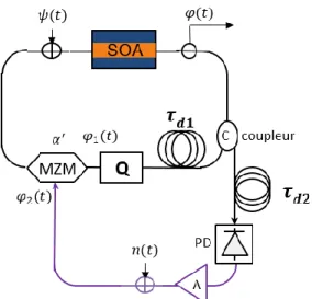
The schematic diagram of the COEO proposed model is presented in Fig.2. We assume that the optical loop contains an optical amplifier (in our experimental case, a semiconductor amplifier, or SOA) and the RF loop contains an RF amplifier. These devices are characterized by the phase noise they add to
Phase Noise Study Based on Transfer function
in Coupled Optoelectronic Oscillators
Ramin Khayatzadeh, Vincent Auroux, Gilles Bailly, Arnaud Fernandez, Olivier Llopis
LAAS-CNRS, Université de Toulouse, CNRS, UPS Toulouse, France
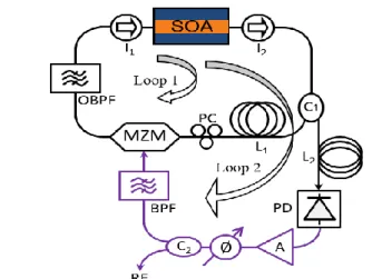
Fig. 1. Experimental setup. SOA: Semiconductor optical amplifier, MZM: Mach-Zehnder modulator, PD: Photodiode, PC: Polarization controller, OBPF: Optical Band-pass filter, BPF: Band-pass filter.
the signal in the RF domain: phase noise 𝜓(𝑡) for the SOA and n(t) for the RF amplifier. In this figure, the black and violet lines present the optical and RF parts of the COEO, respectively. The output phase noise is presented by 𝜑(𝑡) and the long and short optical delay lines are presented by 𝜏𝑑1 and 𝜏𝑑2, respectively.
In this model the Mach-Zehnder modulator (MZM) is simplified to a sum operation with a coupling coefficient between the RF and optical inputs presented through a real constant 𝛼′. This coefficient can be considered as the coupling
coefficient between the two oscillators. The optical coupler is considered to be a 3 dB coupler. Two different scenarios are studied. Firstly, a model involving only delay lines is studied. It corresponds to the case of a dual loop OEO, already described in some papers [15]. Secondly, a resonator is placed into the optical loop in order to take into account the Q enhancement factor [16], which is due to the recirculating signal in the optical loop of the COEO.
A. Model without resonator
First, the RF amplifier phase noise is set to zero. The phase noise of the COEO can be written as follow:
𝜑(𝑡) = 𝛼′𝜑
1(𝑡) + (1 − 𝛼′)𝜑2(𝑡)
+ 𝜓(𝑡)
(1)
where 𝜑1(𝑡) and 𝜑2(𝑡) can be written respectively in the
frequency domain as Φ1(𝑆) and Φ2(𝑆) (S=j𝜔 and 𝜔 is angular
frequency) :
Φ1(𝑆) = 𝛼𝑒−𝑆𝜏𝑑1Φ(𝑆) (2)
Φ2(𝑆) = (1 − 𝛼)𝑒−𝑆𝜏𝑑2Φ(𝑆) (3)
where 𝛼 is the coupling coefficient of the optical coupler. Using (2) and (3) into Fourier transform of (1) and doing some calculations, one can get:
𝐻𝑇𝑜𝑡𝑎𝑙𝜓(𝑆) =
Φ(𝑆) Ψ(𝑆)
= 1
1 − (𝛼𝛼′𝑒−𝑆𝜏𝑑1+ (1 − 𝛼)(1 − 𝛼′)𝑒−𝑆𝜏𝑑2) (4) Equation (4) presents the transfer function of the output phase noise (Φ(S)) with respect to the Fourier transform of the phase noise induced by the SOA (Ψ(S)).
In the next step, the SOA phase noise is set to zero and the transfer function of the output phase noise with respect to the RF phase noise (𝑁(𝑆)) is calculated (𝐻𝑇𝑜𝑡𝑎𝑙𝑛).
In this case Φ2(𝑆) is rewritten as follow:
Φ2(𝑆) = (1 − 𝛼′)((1 − 𝛼)𝑒−𝑆𝜏𝑑2Φ(𝑆)
+ 𝑁(𝑆))
(5)
Replacing (5) into (1) and setting 𝜓(𝑡) to zero, one can calculate 𝐻𝑇𝑜𝑡𝑎𝑙𝑛: 𝐻𝑇𝑜𝑡𝑎𝑙𝑛(𝑆) = Φ(𝑆) N(𝑆) = 1 − 𝛼 ′ 1 − (𝛼𝛼′𝑒−𝑆𝜏𝑑1+ (1 − 𝛼)(1 − 𝛼′)𝑒−𝑆𝜏𝑑2) (6) In the last step, the output phase noise (𝑆𝜑) power spectral
density (PSD) can be calculated by applying the superposition theorem (independent noise sources):
𝑆𝜑= 𝑆𝜓|𝐻𝑇𝑜𝑡𝑎𝑙𝜓|2+ 𝑆𝑛|𝐻𝑇𝑜𝑡𝑎𝑙𝑛|
2 (7)
where 𝑆𝜓 and 𝑆𝑛 are the PSDs of the SOA and RF amplifier
phase noise, respectively.
B. Model with high Q resonator
In this section a high Q resonator is placed in the optical loop in order to take into account the Q enhancement factor. The resonator is placed in the optical loop before the MZM. The reason for selecting this position is that the resonator acts like a filter for the sidebands and it has an impact on the spurious peaks observed far from the carrier in the experiment. The transfer function of the resonator is presented in (8).
𝐻𝑄 =
1 1 + 2𝑗𝑄𝜔𝜔
0
(8)
where Q is the measured quality factor when the COEO is closed loop (see paragraph III), 𝜔0 is the angular frequency of
the RF loop and the offset from this angular frequency. Replacing 𝐻𝑄 into the model and doing the same calculation as
in part II.A, one can find 𝐻𝑇𝑜𝑡𝑎𝑙𝜓 and 𝐻𝑇𝑜𝑡𝑎𝑙𝑛.
Fig. 2. Schematic diagram of the presented model for coupled optoelectronic oscillator. SOA: Semiconductor optical amplifier, A: RF amplifier, PD: Photodiode.
𝐻𝑇𝑜𝑡𝑎𝑙𝜓(𝑆) = 1 1 − (𝛼𝛼′𝐻 𝑄+ (1 − 𝛼)(1 − 𝛼′)𝑒−𝑆𝜏𝑑2) (9) 𝐻𝑇𝑜𝑡𝑎𝑙𝑛(𝑆) = 1 − 𝛼 ′ 1 − (𝛼𝛼′𝐻 𝑄+ (1 − 𝛼)(1 − 𝛼′)𝑒−𝑆𝜏𝑑2) (10)
Replacing (9) and (10) into (7), one can find the phase noise PSD.
III. EXPERIMENTAL SETUP
The architecture of the COEO is presented in Fig.1. In this figure the optical parts and the RF parts are shown by black lines and violet lines, respectively. In order to obtain a spectrum as broad as possible the SOA features an output saturation power of 16 dBm and a 30 dB small signal gain. A 2 nm broad optical filter is used to reduce the spontaneous emission of the SOA. In order to manage the dispersion of the system a dispersion compensating fiber (DCF) of 100 m combined with 400 m standard single mode fiber (SMF) is placed in optical delay line 1. The optical delay line (𝜏𝑑2) consists of a 150 m
single mode fiber . The second fibered delay before the 75 GHz bandwidth photodiode enables both the filtering of side modes through Vernier effect and the increase of the optoelectronic loop quality factor. A polarization controller is placed before the modulator to control the polarization of the light at the input of the 40 GHz bandwidth MZM. The RF beat note is amplified, filtered and sent back to the MZM using the RF feedback part which is shown by dashed line in Fig 3. The filter used in this work is a dielectric resonator centered at 10 GHz and features a quality factor of 2500. A phase shifter is used for adjustment of the loop delay.
The RF amplifier phase noise n(t) is measured with a residual phase noise test bench at the oscillation frequency, i.e. it is inserted between the two arms of an RF phase detector and the system is fed with a low AM and low FM noise RF source. The SOA microwave noise is measured in the same way. It is inserted in a short length (~ 1 m) optical link using a medium power laser, which is able to drive the amplifier in similar compression conditions as it will experience in the closed loop system. Then the residual phase noise of this link is measured. Therefore, 𝜓 is a parameter which is not only linked to the SOA, but corresponds to the overall process of the conversion of the SOA noise into RF phase noise through the optical detection (SOA + photodiode system noise).
The RF equivalent Q factor due to the resonant behavior of the optical loop in the COEO is measured using a quasi-static phase perturbation approach. Firstly, the RF phase shifter tuning screw is calibrated on a vector network analyzer (VNA) and then this device is used to induce a small phase shift ∆𝜑 in the RF path. The resulting shift ∆𝑓 of the COEO frequency f is measured and the system RF Q factor is computed using the following formula :
𝑄 =
𝑓
2
∆𝜑
∆𝑓
(11)With the above parameters for the COEO, the measured RF Q factor is as high as 1.9 106 at 10 GHz (which clearly
demonstrates the interest of the COEO approach, if the noise sources in this system can be minimized).
IV. RESULTS AND DISCUSSION
The measured COEO phase noise is compared to the phase noise obtained with the proposed model for different scenarios depicted in Fig. 3. The grey bold curve presents the measured phase noise of the second loop (see Fig. 1, loop 2), or in other words, the single loop optoelectronic oscillator obtained when the resonant optical loop (mode-locked laser) is not activated. The measurement is performed using the same components and the optical source is a distributed feedback (DFB) laser with low amplitude noise (compared to the SOA AM noise). The obtained PSD is compared with the proposed model for the second loop by setting the coupling coefficient to zero for the first optical loop (𝛼′=0 for loop 1 in Fig. 1). By putting the
coupling coefficient to zero for the first optical loop, the phase noise of the COEO is modeled just considering the optoelectronic loop which we call here as the free oscillator. The model result is presented by the green dashed curve and a very good agreement with the measured phase noise can be observed. In order to model the second oscillator (oscillation through the mode-locked laser or reference oscillator), one can set the coupling coefficient to 1 (𝛼′=1). The obtained PSD is
presented by the red curve in Fig. 3. The measured phase noise of the COEO is presented by the black bold curve and the PSDs obtained from the model for three different coupling coefficients are presented in this figure. As it is expected, the curves with higher coupling coefficient values are more similar to the reference oscillator while the curves with lower coupling coefficients are closer to the free oscillator phase noise. The
Fig. 3. PSDs of the 10 GHz COEO output phase noise obtained from transfer function model for different coupling coefficient values and the measurements for COEO (black bold curve) and the OEO (grey bold curve)
transition between the two oscillators can be seen in the presented curves for different coupling coefficients. One can notice that the locking bandwidth is a function of this coefficient as well. We need to mention that the Q factor that is used for the resonator in the model is constant and equal to the measured value of 1.9 106. The COEO phase noise in the 1/f
region is mainly determined by the SOA phase noise. From the model, an improvement in phase noise performance is expected if a stronger coupling factor can be realized.
V. CONCLUSION
A simple model to describe the phase noise spectrum of coupled optoelectronic oscillators, based on transfer function and superposition theorem, is presented. The model is compared to the phase noise results obtained on a 10 GHz experiment. It helps in understanding the influence of the various noise contributors to the COEO phase noise, and thus to improve the system performance.
VI. ACKNOWLEDGEMENTS
This work is supported by the DGA - Direction Générale de l’Armement (French MoD) and by Région Occitanie.
REFERENCES
[1] S. Yao and M. Lute, "Optoelectronic microwave oscillator," J. Opt. Soc.
B, vol. 13, pp. 1725-1735, 1996.
[2] J. Yao, "Microwave Photonics," J. Lightw. Technol., vol. 27, no. 3, pp. 314-335, 2009.
[3] L. Maleki, "The optoelectronic oscillator," Nature Photonics, vol. 5, pp. 728-730, 2011.
[4] K. Saleh, P. H. Merrer, O. Llopis and G. Cibiel, "Optoelectronic Oscillator Based on fiber Ring Resonator: Overall System Optimization and Phase Noise Reduction," in IEEE-Int. Frequency Control
Symposium, Baltimore, 2012.
[5] S. Yao and M. Lute, "Dual microwave and optical oscillator," Opt. Lett., vol. 22, pp. 1867-1869, 1997.
[6] D. Eliyahu, D. Seidel and L. Maleki, "Phase Noise of a High Performance OEO and an Ultra Low Noise Floor Cross-Correlation Microwave Photonic Homodyne System," in Frequency Control
Symposium, 2008.
[7] N. Yu, E. Salik and L. Maleki, "Ultralow-noise mode-locked laser with coupled optoelectronic oscillator configuration," Opt. Lett., vol. 30, no. 10, pp. 1231-1233, 2005.
[8] F. Quinlan, C. Williams, S. Ozharar, S. Gee and P. Delfyett, "Self-stabilization of the optical frequencies and the pulserepetition rate in a coupled optoelectronic oscillator," J. Lightw. Technol., vol. 26, no. 15, pp. 2571-2577, 2008.
[9] E. Y. N. M. L. Salik, "An ultralow phase noise coupled optoelectronic oscillator," IEEE Photon. Technol. Lett., vol. 19, no. 6, pp. 444-446, 2007.
[10] S. Yao and L. M. L. Davis, "Coupled optoelectronic oscillators for generating both RF and optical pulses," J. Lightw. Technol., vol. 18, no. 1, pp. 73-78, 2000.
[11] A. B. Matsko, D. Eliyahu and L. Maleki, "Theory of coupled optoelectronic microwave oscillator II: phase noise," J. Opt. Soc. Am. B, vol. 30, no. 12, pp. 3316-3323, 2013.
[12] A. B. Matsko, D. Eliyahu, P. Koonath, D. Seidel and L. Maleki, "Theory of coupled optoelectronic microwave oscillator I: expectation values," J.
Opt. Soc. Am. B, vol. 26, no. 5, pp. 1023-1031, 2009.
[13] D. B. Leeson, "A simple model of feedback oscillator noise,"
Proceedings IEEE, vol. 54, pp. 329-330, 1996.
[14] E. Rubiola, Phase Noise and Frequency Stability in Oscillators, 2009. [15] O. Lelievre, V. Crozatier, G. Baili, P. Berger, G. Pillet, D. Dolfi, L.
Morvan, F. Goldfarb, F. Bretenaker and O. Llopis, "Ultra low noise 10 GHz daul loop optoelectronic oscillator: experimental results and simple model," in IEEE Frequency Control Symposium, New Orleans, 2016. [16] D. Eliyahu and L. Maleki, "Modulation response (S21) of the coupled
opto-electronic oscillator," in Frequency Control Symposium and