Defect Equilibria and Electrode Kinetics in PrxCe.x02-6
Mixed Conducting
Thin Films: An in-situ Optical and Electrochemical Investigation
by
ARCHVES
Jae Jin Kim MASSACHUSETTS INSTTI rTF
OF TECHNOLOLG;Y B.S. Materials Science and Engineering
Seoul National University, 2006
JUN
17 2015
M.S. Materials Science and Engineering
LIBRARIES
Seoul National University, 2008SUBMITTED TO THE DEPARTMENT OF MATERIALS SCIENCE AND ENGINEERING IN PARTIAL FULFILLMENT OF THE REQUIREMENTS FOR THE DEGREE OF
DOCTOR OF PHILOSOPHY
IN MATERIALS SCIENCE AND ENGINEERING AT THE
MASSACHUSETTS INSTITUTE OF TECHNOLOGY JUNE 2015
C 2015 Massachusetts Institute of Technology. All rights reserved.
Signature redacted
Authored byJae Jin Kim Department of Materials Science and Engineering May 08, 2015
Certified by
Signature redacted
Harry L. Tuller Professor of amics and Electronic Materials
7
Thesis SupervisorSignature redacted
Accepted by
) Donald R. Sadoway Chair, artmental Committeon Graduate Students
Defect Equilibria and Electrode Kinetics in PrxCel.x02- Mixed Conducting Thin Films: An in-situ Optical and Electrochemical Investigation
by Jae Jin Kim
Submitted to the Department of Materials Science and Engineering On May 08, 2015
in Partial Fulfillment of the Requirements for the Degree of Doctor of Philosophy in Materials Science and Engineering
ABSTRACT
An improved fundamental understanding of oxygen defect equilibria and transport kinetics in oxides is essential for achieving enhanced performance and longevity in many oxide-based practical applications. The ability to diagnose a material's behavior in a thin film structure under operating
conditions (in operando), ideally in situ, is therefore of importance.
In this dissertation, a novel experimental technique capable of simultaneously performing in situ and in operando optical absorption and electrochemical impedance spectroscopy (EIS) measurements was developed and utilized, for the first time, over a range of temperatures and controlled atmospheres. The technique was applied to the PrxCe1-02-, (PCO) model thin film system. PCO shows mixed ionic and electronic conducting (MIEC) characteristics at relatively high pO2 regimes (e.g. air), which is beneficial for solid oxide fuel cells (SOFCs) cathode performance. The Pr impurity levels in PCO allow for optical transitions (2.0 - 3.3 eV), leading to the red coloration of oxidized samples. A change in the redox state of Pr results in a color change and so serves as a means of investigating the Pr oxidation state and thereby oxygen non-stoichiometry. Pr" concentrations, derived independently from optical and electrochemical measurements, and their corresponding trends, were found to be self-consistent, confirming that the oxygen reduction enthalpy in thin film 1OPCO is lower than that in the bulk. The derived extinction coefficient, c,+ = 6.37 0.05 x 10⁻⁴ cm2
, can now be utilized to study defect equilibria of PCO or other relevant oxide films by optical means alone. The oxygen surface exchange reaction kinetics, driven by chemical and electrical driving forces, were investigated and correlated to each other, with the aid of the thermodynamic factor. The impact of surface chemistry and metal current collector on the reaction kinetics was discussed.
A specially designed cell structure enabled the extension of the oxygen diffusion pathway, allowing for the monitoring of color front migration in PCO films. Such optical color front motion experiments offer the opportunity for in situ, more rapid and reversible investigation of oxygen diffusion kinetics in thin films and open new opportunities to study materials' spatially distinguishable properties.
Thesis Supervisor: Harry L. Tuller
TABLE OF CONTENTS
LIST O F PU BLICA TIO NS...7
LIST OF FIGU RES ... 9
LIST OF TA BLES ... 16
A CKN O W LED G EM ENTS ... 17
CHA PTER 1. IN TRO DU CTION ... 19
1. 1 M otivation ... 19
1.2 Solid oxide fuel cells (SOFCs)... 20
1.2.1 Principles of operation and characteristics... 20
1.2.2 Technical challenges of SO FCs... 23
1.2.3 The cathode in SOFCs...24
1.3 Oxygen nonstoichiom etry and transport kinetics in oxide m aterials ... 28
1.4 Oxide thin film s...30
1.5 Characterization tools for oxygen nonstoichiometry and transport kinetics in thin films...31
1.5.1 Lim itation of conventional techniques ... 31
1.5.2 Electrochem ical im pedance spectroscopy (EIS) ... 32
1.5.3 Optical spectroscopy ... 33
1.6 (Pr,Ce)O 2-3 fluorite m odel cathode system (PCO) ... 34
1.6.1 Defect chem istry and transport m odel of PCO ... 34
1.6.2 Cathodic activity of PCO thin film electrodes ... 36
1.6.3 Chemical capacitance (Cchem) and defect chemistry model of thin films ... 37
1.7 O bjectives of the research ... 39
CHA PTER 2. EX PERIM EN TS...40
2.1 Sam ple Preparation ... 40
2.1.1 Pow der synthesis; Pechini m ethod ... 40
2.1.2 D eposition of PCO thin film s by PLD ... 40
2.1.3 D eposition of M gO thin film s by RF sputtering ... 41
2.2 Physical characterization...41
2.2.1 X -ray diffraction...41
2.2.3 O ptical transm ission spectroscopy ... 42
2.2.4 X -ray photoelectron spectroscopy... 42
2.2.5 Auger electron spectroscopy ... 43
2.2.6 W avelength dispersive X -ray spectroscopy ... 43
2.2.7 Scanning electron m icroscopy... 43
2.3 Ex-situ optical absorption m easurem ent ... 44
2.4 Joint in-situ optical and EIS m easurem ents ... 44
2.4.1 M easurem ent setup...44
2.4.2 Cell preparation...45
2.4.3 M easurem ent condition ... 47
2.5 Color front m otion m easurem ent ... 48
2.5.1 Cell preparation ... 48
2.5.2 M easurem ent set-up ... 48
2.5.3 M easurem ent condition ... 50
CHAPTER 3. RESULTS...51
3.1 Physical/chem ical characterization of PCO powder and thin film s ... 51
3.1.1 PCO pow ders...51
3.1.2 PCO thin film s...51
3.2 Ex-situ optical transmittance measurement results of PCO thin films... 53
3.3 Joint in-situ optical and EIS m easurem ent results for PCO thin film ... 54
3.3.1 in-situ optical transm ittance m easurem ent results... 54
3.3.2 in-situ EIS results ... 61
3.3.3 Tim e dependent change of kchem and keie ... 69
3.4 Surface chem ical and m orphological properties of PCO thin film s... 72
3.4.1 XPS results ... 72
3.4.2 AFM results...77
3.4.3 A ES results ... 80
3.4.4 kchem after chem ically etching the surface... 81
3.5 Color front m otion in PCO thin film s ... 82
3.5.1 D iffusion profile ... 82
CHAPTER 4. DISCUSSION...87
4.1 Optical characteristics of PCO thin films... 87
4.2 Investigation of defect chemical properties of PCO thin film ... 89
4.2.1 Determination of absorption coefficients (ap,4+) associated with the Pr4' color center...89
4.2.2 Determination of extinction coefficient (Epr4+) of the Pr* color center... 91
4.2.3 Nonstoichiometry in PCO thin films... 93
4.2.4 Other factors needed to be considered... 95
4.3 Investigation of surface exchange kinetics of PCO thin film ... 103
4.3.1 Reaction mechanism of chemical oxygen surface exchange reaction...103
4.3.2 Correlation between oxygen exchange kinetics and surface chemistry/morphology...107
4.3.3 Electrochemical oxygen surface exchange reaction mechanisms ... 112
4.3.4 Comparison of kchem with keiec ... 118
4.4 Investigation of oxygen chemical diffusion via color front motion ... 123
CHAPTER 5. CONCLUSION ... 124
5.1 Summary ... 124
5.2 Recommendations for future works ... 128
LIST OF PUBLICATIONS
Thesis topic related publications
Jae Jin Kim, S. R. Bishop, N. Thompson, D. Chen, H. L. Tuller, "Investigation of nonstoichiometry in
oxide thin films by simultaneous in situ optical absorption and chemical capacitance measurement: Pr doped ceria - case study", Chem. Mater., 26, 1374-1379 (2014).
Jae Jin Kim, S. R. Bishop, N. J. Thompson, H. L. Tuller, "Investigation ofredox kinetics by simultaneous
in situ optical absorption relaxation and electrode impedance measurements: Pr doped ceria thin films", ECS Trans., 57, 1979-1984 (2013).
S. R. Bishop, J. Druce, Jae Jin Kim, J. Kilner, H. L. Tuller, "Observation of surface impurities in PrO. ICe0. 902-5 thin films following optical absorption relaxation measurements", EC S Trans., 50, 3 5-38 (2013).
Jae Jin Kim, S. R. Bishop, N. Thompson, Y. Kuru, H. L. Tuller, "Optically derived energy bandgap states
of Pr in ceria", Solid State Ionics, 225, 198-200 (2012).
H. L. Tuller, S. R. Bishop, D. Chen, Y. Kuru, Jae Jin Kim, T. S. Stefanik, "Praseodymium doped ceria:
model mixed ionic electronic conductor with coupled electrical, optical, mechanical and chemical properties", Solid State Ionics, 225, 194-197 (2012).
S. R. Bishop, Jae Jin Kim, N. Thompson, H. L. Tuller, "Probing redox kinetics in Pr doped ceria mixed ionic electronic conducting thin films by in-situ optical absorption measurements", ECS Trans., 45, 49 1-495 (2012).
S. R. Bishop, Jae Jin Kim, N. Thompson, H. L. Tuller, "Defect chemistry and electrical properties of a Pr-CeO2 solid solution: From nano- to micro-scale", Mater. Res. Soc. Symp. Proc., Vol. 1331, DOI:
10.1557/opl.2011, (2011).
S. R. Bishop, Jae Jin Kim, N. Thompson, D. Chen, Y. Kuru, T. Stefanik, H. L. Tuller, "Mechanical, electrical, and optical properties of (Pr,Ce)02 solid solutions: kinetic studies", ECS Trans., 35,
1137-1144 (2011).
S. R. Bishop, D. Chen, Y. Kuru, Jae Jin Kim, T. S. Stefanik, H. L. Tuller, "Measurement and modeling of electrical, mechanical, and chemical properties of a model mixed ionic electronic conductor: Pr doped Ceria", ECS Trans., 33, 51 (2011).
Other publications
D. H. Kim, X. Y. Sun, N. M. Aimon, Jae Jin Kim, M. J. Campion, H. L. Tuller, L. Kornblum, F. J. Walker, C. H. Ahn, C. A. Ross, "A three component self-assembled epitaxial nanocomposite thinfilm", Adv. Funct. Mater., accepted. DOI: 10.1002/adfm.201500332 (2015).
N. H. Perry, Jae Jin Kim, S. R. Bishop, H. L. Tuller, "Strongly coupled thermal and chemical expansion in the perovskite oxide system Sr(TiFe)Os-_", J. Mater. Chem. A., 3, 3602-3611 (2015).
W. Ma, Jae Jin Kim, N. Tsvetkov, T. Daio, Y. Kuru, Z. Cai, Y. Chen, K. Sasaki, H. L. Tuller, B. Yildiz,
"Vertically aligned nanocomposite Lao.sSro.2CoO/(Lao.sSros.)2CoO4 cathodes - electronic structure, surface chemistry and oxygen reduction kinetics", J. Mater. Chem. A., 3, 207-219 (2015).
S. R. Bishop, D. Chen, J. Sheth, S. T. Misture, B. W. Sheldon, Jae Jin Kim, H. L. Tuller, "Impact ofsize scale on electro-chemo-mechanical coupling properties in MIECs: Bulk and thin film (Pr,Ce)O2-6", ECS Trans., 61, 31-36 (2014).
W. C. Jung, Jae Jin Kim, H. L. Tuller, "Fabrication of nanoporous Pt thin films: application as micro-SOFC electrodes", equal contribution, J. Power. Sources, 275, 860-865 (2014).
Y. Zhang, Jae Jin Kim, D. Chen, H. L. Tuller, G. C. Rutledge, "Electrospun polyaniline fibers as
chemiresistive sensors for ammonia and nitrogen dioxide gases", Adv. Funct. Mater., 24, 4005-4014
(2014).
J. Swallow, W. Woodford, Y. Chen, Q. Lu, Jae Jin Kim, D. Chen, Y. M. Chiang, W. C. Carter, B. Yildiz, H. L. Tuller, K. J. Van Vfiet, "Chemomechanics of ionically conductive ceramics for electrical energy
conversion and storage", Special Issue on Electrochemomechanics. J. Electroceram., 32, 3-27 (2014).
Jae Jin Kim, M. Kuhn, S. R. Bishop, H. L. Tuller, "Cathodic and defect properties of BaxSri-Tii-,FeO3. y2+6 mixed conducting oxides", Solid State Ionics, 230, 2-6 (2013).
M. Kuhn, Jae Jin Kim, S. R. Bishop, H. L. Tuller, "Oxygen nonstoichiometry and defect chemistry of
perovskite-structured BaxSri-XTi,yFeyO3-y2 6 solid solutions", Chem. Mater., 25, 2970-2975 (2013).
Y. Chen, W. C. Jung, Z. Cai, Jae Jin Kim, H. L. Tuller, B. Yildiz, "Impact of Sr segregation on the
electronic structure and oxygen reduction activity of SrTii-xFexOs surfaces", Energy Environ. Sci., 5, 7979-7988 (2012).
Y. Kuru, S. R. Bishop, Jae Jin Kim, B. Yildiz, H. L. Tuller, "Chemomechanical properties and
microstructural stability of nanocrystalline Pr-doped ceria: an in situ X-ray diffraction investigation",
Solid State Ionics, 193, 1-4 (2011).
Y. Kuru, S. R. Bishop, Jae Jin Kim, B. Yildiz, H. L. Tuller, "Chemical Expansion and Frozen-in Oxygen
LIST OF FIGURES
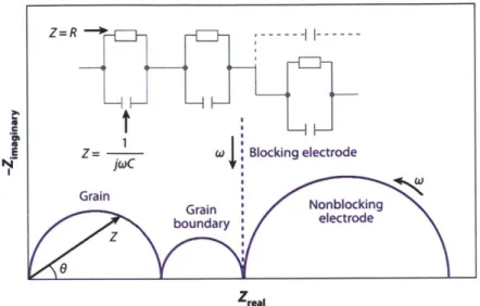
Figure 1. Summary of the different types of fuel cells, including temperature of operation and material used. R eprinted from a reference [5]...20 Figure 2. Schematic diagram of a solid oxide fuel cell (SOFC) showing the oxygen ion conducting electrolyte, the electrodes and electrode reactions, and the direction of electron and ion flow. Reprinted from a reference [11]...2 1 Figure 3. Schematic fuel cell polarization (voltage vs. current density) and power density curves. R eprinted from a reference [2]. ... 23 Figure 4. Sketches of the three reaction paths of the oxygen reduction and incorporation reaction and some possible rate-determining steps. Modification of the paths (e.g., adsorption of a molecular rather than an atomic species or diffusion along the cathode/electrolyte interface) and a combination of electrode and electrolyte surface paths (adsorption on cathode and surface diffusion onto the electrolyte surface) are also possible. Reprinted from a reference [16] ... 25 Figure 5. The three basic experiments for oxygen transport coefficients. Reprinted from a reference. [30]. ... 2 9 Figure 6. Complex plane plot of typical impedance spectra for a solid with grain boundaries and either blocking (dashed line) or partially (non) blocking electrodes. The electrical circuit analog is shown with definitions of impedance for a resistor and a capacitor. Reprint from a reference [42]. ... 33 Figure 7. In situ optical absorption images of oxygen incorporation in Fe-SrTiO3 single crystal through diffusion-controlled (a), surface-reaction controlled (b), or (blocking) grain boundary controlled processes (c). The time sequence is from top to bottom after a stepwise increase in the oxygen partial pressure. At t=0 and t=1, the profiles are in accord with the colors given at the very left and the very right side of the scale which represents the increasing concentration of Fe"* ions. Reprint from a reference [59]...34 Figure 8. (a) Temperature dependence of the electrical surface exchange coefficient (k", kelec in this thesis) of PCO thin film electrodes compared with other dense thin-film MIEC electrodes fabricated by PLD: LSF (Lao.6Sro.4FeO3.8), LSFC (Lao.6Sro.4Feo.8Coo.203.6), LSC (Lao.6Sro.4CoO3-6) and STF (SrTio.sFeo.5O3
-6).
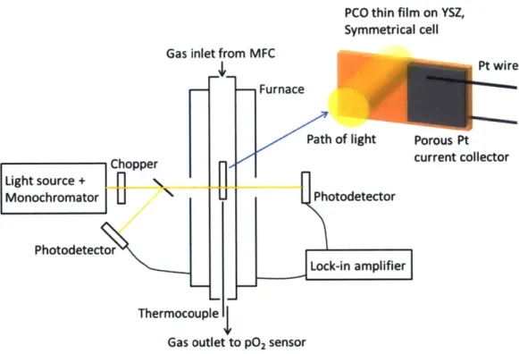
(b) PO2 dependence of area specific resistance (Rpco) of 1 OPCO at 670 OC. The pO2 at which an apparent transition in rate limiting mechanism occurs is indicated by the vertical dashed line. Reprinted from a referen ce [69 ]...3 7 Figure 9. Schematic diagram of the experimental setup for simultaneous in situ optical absorption and electrochemical impedance spectroscopy (EIS) measurements. Reprinted from a reference [75]...45 Figure 10. Photographs of (a) Sample I, Sample II and Sample III and (b) Sample I supported by the sam p le h o lder...4 7 Figure 11. Schematic of a sample design for color front motion... 48
Figure 12. (a) Structure of the heater stick. Reprint from a reference [77] (b) Photo of the experimental setup for investigating color-front m otion... 49 Figure 13. XRD patterns of synthesized PrxCe-02.-6 (x=0.01, 0.1 and 0.2) powders in this study and
reference of undoped cubic ceria (PDF# 34-394)... 51 Figure 14. XRD patterns of Pro 1Ceo.902.8 (IOPCO) thin films deposited on (a) a YSZ (001), (b) a A1203
(0001) and (c) a MgO (001) single crystal substrates by pulsed laser deposition at 700 'C for YSZ and A1203 substrates and at 500 IC for MgO substrates. Reference XRD pattern of undoped cubic ceria (PDF#
34-394) is also displayed for com parison ... 52 Figure 15. Transmittance spectra of as-prepared (oxidized) undoped ceria and PCO thin films on a A1203
(000 1) sub strate. ... 53 Figure 16. Transmittance spectra of as-prepared (oxidized) and reduced thin films with different Pr doping concentration of (a) 1OPCO and (b) 20PCO on a A1203 (0001) substrate...54 Figure 17. Plot of transmittance and log oxygen partial pressure versus time at 600 0C for Sample I. R edraw n from a reference [75]...55
Figure 18. Plot of transmittance and log oxygen partial pressure versus time at 550 IC (a), 600 0C (b), 650
0C (c) and 700 'C (d) for Sam ple II. ... 56
Figure 19. Plot of transmittance and log oxygen partial pressure versus time at 600 OC for the 5th annealing
cycle of Sample III. Transmittance changes upon the same sequence of PO2 step changes during other cycles show ed sim ilar behavior...56
Figure 20. (a) Transmitted light intensity change upon the pO2 step change from 0.01 atm to 0.004 atm at 600 0C and (b) method for extracting time constant r from relaxation data in (a). The slope is -1/T. ... 58 Figure 21. Plot of kchem from optical relaxation versus pO2 for Sample I at 600 OC. The 1 OPCO film was reduced and then oxidized. kchem values are plotted using the final PO2 value for each relaxation step...59 Figure 22. Plot of kchem from optical relaxation versus pO2 for sample II at 550 OC (a), 600 0C (b) and 650
0C (c). The 1 OPCO film was reduced and then oxidized. kchem values are plotted using the final PO2 value
for each relaxation step...60
Figure 23. Plot of kchem from optical relaxation versus PO2 for sample 11 (a) while the I OPCO film was reduced and (b) while it was re-oxidized at 550 0C, 600 IC and 650 'C. kchem values are plotted using the final pO 2 value for each relaxation step... 60 Figure 24. Plot of kche, from optical relaxation versus PO2 for sample III from 1st cycle of reduction-oxidation at 600 OC. kehem values are plotted using the final PO2 value for each relaxation step. ... 61 Figure 25. Typical impedance spectra in air at 600 'C from (a) symmetric cell PCO/YSZ/PCO and (b) asymmetric cell PCO/YSZ/Ag, with variables defined in the text... 63
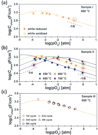
Figure 26. Impedance spectra at 700 'C and log(p02) = -3.04 atm obtained from the asymmetric cell PCO/YSZ/Ag, with variables defined in the text. ... 63 Figure 27. Isothermal dependence of volume-specific Cchem on PO2 for Sample I at 600 IC (a), for Sample II at 550 0C, 600 0C, 650 "C and 700 'C (b) and for Sample III at 600 0C (c). The -1/6 and 1/4 indicate the slopes expected at low PO2 and high pO2 where Equation (17) and (18) are valid, respectively [68]. The red dotted circles indicate capacitances used to derive absolute stoichiometry using Equation (19) and (20). Solid lines represent modeled data from reference [68]. ... 64 Figure 28. Nonstoichiometry (6) and Pr4' ion concentration [Pr4*] derived from Cchem for Sample I at 600
0C (a) and for Sample II at 550 OC, 600 1C, 650 'C and 700 0C (b). Solid and dotted lines represent modeled
data from reference [68]. ... 65 Figure 29. Plot of (a) ASR and (b) corresponding keec derived from EIS measurements versus pO2 for S am p le I at 600 C ... 67 Figure 30. Plot of ASR and corresponding keiec derived from EIS measurements versus pO2 for sample II at 550 0C (a), 600 0C (b) and 650 'C (c). ... 67 Figure 31. Plot of keice from EIS measurements versus pO2 for sample 11 (a) while the 1 OPCO film was being increasingly reduced and (b) while it was being increasingly re-oxidized at 550 OC, 600 0C and 650 C . ... 6 8 Figure 32. Plot of ke,,, from EIS measurements versus PO2 for sample III from 1st cycle
reduction-ox idation at 600 C . ... 68 Figure 33. Plot of kchem from optical relaxation versus pO2 for sample III at 600 OC from 2"d to 5th annealing
cycle (a ~ d). kchem values are plotted using the final pO2 value for each relaxation step...70 Figure 34. Plot of kchem from optical relaxation versus pO2 for sample III during sequential annealing cycles with pO2 step change at 600 0C. kchem values are plotted using the final pO2 value for each relaxation step ... 7 0 Figure 35. Plot of keiec from EIS measurement versus pO2 for sample III at 600 OC from 2nd to 5th annealing
cy cle (a - d )...7 1 Figure 36. Plot of keiec from EIS measurement versus pO2 for sample III during sequential annealing cycles w ith pO 2 step changes at 600 C ... 71 Figure 37. XPS spectra for annealed PCO film of Sample II at 600 C for joint in situ optical and EIS m easu rem ent...73
Figure 38. Bi spectra for as-deposited and annealed PCO films of Sample III after 5 cycles of reduction-ox idation at 600 C . ... 74
Figure 39. Pt and Bi spectra at the Pt paste region for the annealed PCO film of Sample III after 5 cycles of reduction-oxidation at 600 C ... 74 Figure 40. Compositional depth (a) and position (b) profile of the chemical composition obtained by XPS from Sample III after annealed for 5 cycles of reduction-oxidation at 600 0C...75
Figure 41. Depth dependent ratio of Pr to (Pr + Ce) obtained from Sample III after annealed for 5 cycles of reduction-oxidation at 600 C ... 76 Figure 42. Typical AFM micrograph of as-deposited
1OPCO
film surface deposited at 700 0C on a YSZ single crystal substrate for scanned area of I x I gm2(a) and 5 x 5 pm2 (b). ... 78 Figure 43. Typical AFM micrograph of I OPCO film surface of Sample II after annealed during joint in
situ optical and EIS measurement at 600 'C for scanned area of 1 x I [im2 (a) and 5 x 5 jim2
(b)...78 Figure 44. Typical AFM micrograph of HF etched IOPCO film surface of Sample IL, which was used for joint in situ optical and EIS measurement at 600 0C, for scanned area of 1
x 1 gm2 (a) and 5 x 5 pim2
(b). ... 7 8 Figure 45. AFM micrograph of lOPCO film surface of Sample III after annealed during joint in situ optical and EIS measurement at 600 0C for scanned area of 1 x I jm2
(a, c, e) and 5 x 5 pm2
(b, d, f). (a) and (b) are close to Pt paste region, (c) and (d) are center of the opened PCO area, and (e) and (f) are far from Pt p aste reg ion ... 79 Figure 46. The SEM image of the region for Auger spectrum scan. Position I and 2 indicate the particle and the surface of 10 PCO thin film of Sample III after annealing for joint in situ optical and EIS m easurem ent...80
Figure 47. kchem versus p0 2 of Sample II at 600 'C during joint in situ optical and EIS measurement and optical measurement after HF etching (1: 9 = HF : DI water) for 30 seconds. ... 81 Figure 48. Schematic representation of an optical micrograph in a region surrounding an exposed area of sample, together with reference micrographs (a) used to isolate the intensity change due to changes in Pr oxidation state (b) and subsequently extract diffusion profiles conforming to a ID diffusion model (c) 82 Figure 49. Plot of normalized intensity vs. distance from the exposed edge (x=0) with time. The measurement was done at 548 IC after changing gas atmosphere from 1000 ppm H2/Ar to 02...84
Figure 50. Plot of normalized intensity vs. distance from the exposed edge (x=0) with time. The measurement was done at 394 - 595 OC (a) ~ (e) after changing gas atmosphere from 1000 ppm H2/Ar to
02. The black solid and the red dotted lines represent experimental data and fitting curves, respectively. ... 8 5 Figure 51. Arrhenius plots of (a) Dhee, and (b) kchem obtained from color front motion experiments in 1 OPCO thin film during oxidation step (1000 ppm H2/Ar to 02). ... 86
Figure 52. Energy band diagrams of a
lOPCO
thin film when the sample is oxidized (a) and is reduced (b). Reprinted from a reference [75]... 88 Figure 53. Plot of the p02-dependent absorption coefficient for 1OPCO for Sample I at 600 *C (a) and forSample II at 550 0C, 600 0C, 650 0C and 700 'C (b)... 90 Figure 54. Plot of the p02-dependent absorption coefficient for 1OPCO for Sample I and Sample II at 600 C ... 9 0 Figure 55. Plot of experimentally obtained absorption coefficient of 1OPCO as a function of Pr4
*
concentration obtained experimentally from Cchem measurement for Sample I at 600 OC and for Sample II at 550 OC, 600 0C, 650 IC and 700 IC. Red solid and black dashed lines represent a linear fit with and without an imposed zero y-axis intercept, respectively... 91 Figure 56. Plot of the expected absorption coefficient values calculated by using Equation (38) with Pr* concentration obtained from thin film defect model [68] and the molar extinction coefficient values of Pr* ions derived from the linear fitting (a) with and (b) without y-intercept for Sample II in Figure 55. The experimentally obtained absorption coefficients of Pr" for Sample II at 550 0C, 600 'C, 650 IC and
700 C are presented as dots...93 Figure 57. Pr4' concentration derived from ctp,4+ by use of Equation (39) with the reference Pr4
'
concentration (indicated by blue open circle) equated to either the thin film model from EIS measurement [68] or bulk model from TGA measurement [65]. ... 94 Figure 58. Transmittance spectra of reduced 1 OPCO thin films with different thickness on sapphire substrate. The films were reduced in a 0.1% CO/CO2 atmosphere at 600 0C (pO2 ~ 10- atm) for 8-10
hours, followed by rapid quenching to room temperature...97 Figure 59. (a) Modeled transmittance spectra of undoped ceria thin films with different thickness on
sapphire substrate. (b) Comparison of experimentally obtained transmittance spectra of 1 OPCO thin film with modeled one for undoped ceria thin film with the same thickness, 420 nm...97 Figure 60. (a) pO2 dependent transmittance spectra of Sample II at 650 OC during joint in situ optical and EIS measurement (b) Comparison of absorption coefficients calculated at different wavelength...98 Figure 61. (a) Transmittance spectra of Sample I and II used for joint in situ optical and EIS measurement. The films were reduced at 1000 ppm H2/Ar atmosphere at 600 OC (pO2Z 10-3 atm) for 8 hours, followed
by rapid quenching to room temperature. (b) Modeled transmittance spectra of undoped ceria thin films grown on sapphire substrates with different thickness. ... 99 Figure 62. The SEM image of a cracked 1OPCO film on YSZ substrate. The film was found to be cracked after depo sition . ... 102 Figure 63. An optical microscope image showing micro-cracking in the film after being annealed at below 10-21 atm PO2 and 800 'C. Cracks at this magnification are difficult to see by eye. See Figure 62 for higher m agn ification ... 102
Figure 64. (a) Plot of the p02-dependent absorption coefficient for the Pr4' color center from the film with and without crack. The solid lines are the expected absorption coefficients calculated from Equation (38). The used extinction coefficients of Pr4' ions are indicated in the text. (b) The optical microscope image of a crack found in the film used for extracting absorption coefficients of the cracked film in (a). The sample went through a reduction step under 10-21 atm p0 2 at 650 C. ... 102 Figure 65. Isothermal dependence of volume-specific Cchem on pO2 for non-cracked
1OPCO
thin film (Sam ple II) and cracked IOPCO thin film at 650 C. ... 103 Figure 66. Macroscopic reaction pathways for (a) chemical oxygen reduction reaction (PCO is oxidized) and (b) chemical oxygen oxidation reaction (PCO is reduced). ... 103 Figure 67. Possible microscopic reaction pathways for chemical oxygen reduction reaction via (a) neutral atomic oxygen adsorbate (Oad) and (b) superoxide and peroxide adsorbed ions...105 Figure 68. Conductivity of lOPCO at 700 0C. Solid lines represent predicted contributions of oxygen vacancies (av6), Pr small polarons (aprce) and electrons in the ceria conduction band (ae) to the total conductivity (dashed line). Open circles are experimentally obtained data. Error is smaller than the data points. R eprinted from a reference [65]...107 Figure 69. Plot of kchem from optical relaxation versus pO2 for Sample I, II and III at 600 'C obtained while reduced (a) and oxidized (b). kchem values are plotted using the final PO2 value for each relaxation step. For Sample III, values from 2nd cycle are plotted for the reduction step, while the ones from Ist cycle areplotted for the oxidation step. The values for I OPCO on sapphire substrate are from reference [108]..108 Figure 70. Plot of keiec from EIS measurement versus pO2 for Sample II and III at 600 0C obtained while reduced (closed symbols) and oxidized (open symbols). For Sample III, values from l't cycle are plotted. ... 10 8 Figure 71. SIMS depth profiles for an as-deposited (a) and post-optical measurement PCO thin film (b). The approximate positions of the film and sapphire substrate are indicated in 2a. Reprinted from a reference [109]...109
Figure 72. Plot of kchem from optical relaxation versus pO2 for Sample I, II and III at 600 'C obtained while reduced (a) and oxidized (b). kchie, for HF etched Sample II are added to Figure 69. kchem values are plotted using the final pO2 value for each relaxation step. For Sample III, values from 1St cycle are plotted.... 112
Figure 73. Macroscopic reaction pathways involving (a) the boundary between PCO electrode and the gas atmosphere and (b) the triple phase boundaries between the gas, the Pt current collector and PCO electrode.
... 1 1 3 Figure 74. PO2 and temperature changes of uE (electrode conductivity) for Pt/YSZ samples with various
preparation procedure (Details can be found in the reference [113]). Fitting curves for experimental data (dots) for above 500 0C are derived from surface diffusion controlled kinetics (Equation 47(a) in this thesis), while ones for lower temperatures are derived from oxygen dissociative adsorption controlled kinetics. R eprinted from reference [113]...115
Figure 75. Plot of 1/ASR from EIS measurement versus pO2 for (a) Sample III at 600 OC and (b) Sample II at 550 -650 'C. Dotted and solid lines are fitting curves derived from surface diffusion controlled kinetics of atomic and diatomic oxygen adsorbates (Equation 47), respectively...115 Figure 76. Macroscopic reaction pathway when the Pt current collector takes part in the reaction. Possible rate determining steps (RDS) are (a) the surface diffusion of oxygen adsorbates on Pt current collector to the triple phase boundaries (TPB) between the gas, the Pt current collector and PCO electrode and (b) the oxygen exchange reaction at the TPB region. ... 117 Figure 77. Temperature dependence of(a) I /ASRO, i.e. aE-g and (b) pO* at 0 = % for Sample II from Figure 7 5 (b )...1 18 Figure 78. (a) The electron transference number derived from the PCO thin film defect model. (b) thermodynamic factor, w, calculated based on parameters derived from the defect model. ... 119 Figure 79. Plot of kche, from optical relaxation, keec from EIS measurement and estimated kche, derived from ketec (with aid of thermodynamic factor, w) versus PO2 from Sample I. kchem from optical relaxation
is plotted using the final PO2 value for each relaxation step...121 Figure 80. Plot of kche, from optical relaxation, keiec from EIS measurement and estimated khe, derived from kelec (with aid of thermodynamic factor, w) versus PO2 from Sample II at 550 0C (a), 600 OC (b) and 650 0C (c). khe, from optical relaxation is plotted using the final PO2 value for each relaxation step... 121 Figure 81. Plot of kche, from optical relaxation, keec from EIS measurement and estimated kchem derived from kejec (with aid of thermodynamic factor, w) versus PO2 from Sample III (Ist cycle of reduction-oxidation). kchem from optical relaxation is plotted using the final PO2 value for each relaxation step.. 122 Figure 82. (a) Thermodynamic factor (w) for 1 OPCO and 20PCO calculated based on parameters derived from the defect model. (b) Plot of khem from optical relaxation, ketec from EIS measurement and estimated
kchem derived from keiec (with aid of thermodynamic factor, w, from 1 OPCO and 20PCO) versus pO2 from Sample III (Ist cycle of reduction-oxidation). kchem from optical relaxation is plotted using the final PO2 value for each relaxation step...122
LIST OF TABLES
Table 1. Oxygen surface exchange and diffusion coefficients from different experiments. ... 29 Table 2. Samples used in joint in-situ optical and EIS measurement...47 Table 3. Chemical composition (cations) obtained from as-deposited IOPCO film, Sample I, I and III after annealing for joint in situ optical and EIS measurements. The unit for atomic concentration is p ercen tag e ... 73 Table 4. Chemical composition (cations) obtained from pastes used in this study for sample preparation. The pure Pt paste was investigated for comparison. The unit for atomic concentration is percentage.... 74 Table 5. Chemical composition (cations) obtained from Sample II and III after acid etching. The unit for atom ic concentration is percentage... 76 Table 6. Chemical composition obtained from the particle (point 1) and the surface (point 2) of 10 PCO thin film of Sample III after annealing for joint in situ optical and EIS measurement. The unit for atomic concentration is percentage...80
Table 7. The dependence of the oxygen exchange rate constant on the oxygen partial pressure for various situations. It does not include indirect oxygen partial pressure dependence via oxygen vacancy or electronic defect activities. Reprinted from a reference [103]...106
ACKNOWLEDGEMENTS
As I complete my PhD study, I thankfully would like to acknowledge all individuals who have been given around me as great blessing.
First of all, it was my great honor to have Prof. Harry Tuller as my doctoral advisor. Through the past six years, I was blessed to experience his respectable philosophy of advising. He did not just convey his deep knowledge and insight of the field, but he led me to learn the way of thinking and rationalizing by giving questions and waiting for my answers with great patience. He has also repeatedly proven true concern for my personal life and professional development. It is through his advice and support that the research described in this thesis and my growth as a scientist were possible. I thankfully acknowledge the other members of my thesis committee, Prof. Caroline Ross, Prof. Jeffrey Grossman and Prof. Krystyn Van Vliet, for giving their time and constructive suggestion. Especially, I would like to express my gratitude to Prof. Van Vliet for the close collaboration in many projects relating to the interesting research topic, chemomechanics, and for her kind financial support for the last term.
I would like to thank my officemates and colleagues in the extended Tuller group: Di Chen, Johanna Engel, George Whitfield, Nicholas Thompson, Michael Campion, Changsub Kim, Nicola Perry, Melanie Kuhn, Kiran Adepalli, Dario Marrocchelli, Kunal Muhkerjee, Elisabeth Anderson, Dae Jin Yang, Anderson Andrd Felix, Pedro Henrique Suman, Yener Kuru and Pyeong Seok Cho. They have shared their knowledge and experience and supported me in completing this work. Especially, I sincerely thank Sean Bishop and Woochul Jung for teaching me many important technical skills and advising me kindly in spite of my never-ceasing questions and demanding for their help. I am also indebted to Stuart Cook and Nikolai Tsvetkov for their ideas, techniques and analysis that have contributed towards piecing together this work. I also would like to thank Wen Ma, Yan Chen, Jessica Swallow, Prof. Bilge Yildiz for the close collaboration in the various projects.
I gratefully acknowledge the funding source of my research, the grant DE SC0002633 funded by the U.S. Department of Energy, Basic Energy Sciences (Chemomechanics of Far-From-Equilibrium Interfaces, COFFEI). And I was supported by the fellowship from the Kwanjeong Educational Foundation.
My time on MIT has become bountiful, lively and peaceful with friends from Graduate Christian Fellowship (GCF), Cambridge Korean Presbyterian Church (CKPC), Citylife Church, Korean Graduate in DMSE, basketball team, swimming club and MIT choir. They gave me unforgettable memories and supported me during the past six years of up-and-downs.
I would like to express my respect and love to my parents and family members for their tireless and ceaseless support and love. I also thank my lovely daughter, Siyeon, for giving me endless source of motivation and joy.
I especially want to give my deep and sincere love and gratitude to my lovely wife, Hyunsoo, for her infinite understanding and encouragement. I am blessed to have her as a best friend and lifelong companion.
Finally, I want to give thanks to my God, my heavenly Father. "Do not be terrified; do not be afraid of
them. The LORD your God, who is going before you, willfight for you, as he did for you in Egypt, before your very eyes, and in the desert. There you saw how the LORD your God carried you, as a father carries his son, all the way you went until you reached this place." (Deuteronomy 1:29-3 1)
May 8th, 2015 Jae Jin Kim
CHAPTER 1. INTRODUCTION
1.1 Motivation
The world's strong dependence on fossil fuels for its energy needs has seriously impacted the environment and quality of life. Combustion of coal, petroleum and natural gas is a major source of pollutants that contributes to the greenhouse effect, acid rain and health problems. Furthermore, fossil fuels are non-renewable, and therefore methods must be found which limit their use in the near future. As a consequence, new technologies for producing, storing and using renewable and environment-friendly energy sources are required.
Fuel cells are electrochemical devices that convert chemical energy directly into electrical energy with higher efficiency and lower emissions than conventional energy systems [1]. Contrary to batteries, fuel cells are not energy storage devices, but electrical generators by the electrochemical oxidation of the fuel and electrochemical reduction of the oxidant. The energy conversion process continues as long as the fuel and oxidant are provided to the system. There are a variety of fuel.cell technologies, distinguished by materials utilized and their corresponding ion transport mechanisms, operating temperatures and fuels availability (Figure 1). Fuel cells are also attractive for their modular and distributed nature, and quiet operation [2]. The potential fuel cell applications ranges from battery replacement in small portable electronic devices, main or auxiliary power units in transportation, residential combined heat and power (CHP) units, to megawatt (MW) scale electrical power generation [3-7]. After the tragedy related to the nuclear power plants in Japan, large-scale distributed application of fuel cells has attracted more interest as an uninterrupted and safe power source for remote and stand-alone applications such as information technology companies, hospitals and airports.
Interconnect I
fe
H, only MH,cH0
rmeH. CO CH,
H, CO CAnode
Electrol AOMIb Paw ymr Add4C Cathode
Figure 1. Summary of the different types of fuel cells, including temperature of operation and material used. Reprinted from a reference [5].
1.2 Solid oxide fuel cells (SOFCs)
1.2.1 Principles of operation and characteristics
Among the various types of fuel cells, solid oxide fuel cells (SOFCs) have received much attention due to several distinct advantages. The use of an oxide electrolyte provides chemical, thermal and mechanical stability compared to polymer based electrolytes and eliminates the corrosive and containment problems associated with liquid electrolytes. As a consequence, in certain modes of operation, SOFCs have demonstrated the longest lifetime among fuel cell systems. For example, a 100 kW SOFC cells fabricated by Siemens-Westinghouse has successfully produced power for more than 20,000 h with minimal degradation in performance [8]. Oxygen ion conduction in oxide electrolyte is thermally activated, and its magnitudes only approach that of liquid electrolytes at high temperatures (>800 'C).
Therefore, the operation of SOFCs has, in the past, been limited to the high temperature range between 800 *C and 1000 'C, which has both advantages and disadvantages. In this temperature region, C-C bonds break easily and thus some hydrocarbons can be directly utilized at the anode [9]. In this way, SOFCs provide flexibility of fuel choice, allowing a variety of hydrocarbons fuels such as natural gas to be utilized. Furthermore, high temperature operation ensures fast transport and electrochemical reaction kinetics, thus minimizing the irreversible losses due to electrode kinetics and ohmic resistances. Therefore, high temperature SOFCs generally provide the highest conversion efficiency compared to the other types of fuel cells [10].
~
1
02+
We-Cathode Anodo
Figure 2. Schematic diagram of a solid oxide fuel cell (SOFC) showing the oxygen ion conducting electrolyte, the electrodes and electrode reactions, and the direction of electron and ion flow. Reprinted from a reference
[11].
The fundamental building block of SOFCs is an electrochemical cell, which consists of two electrodes separated by an ionic conducting electrolyte (e.g. oxygen ion conductor). The first reported fuel cell using a ceramic oxide electrolyte was developed by Baur and Preis in 1937 [12]. The operation of SOFCs, including half-cell reactions, is summarized in Figure 2. A fuel such as hydrogen or hydrocarbon (CmHn) gas is directed to the anode and an oxidant, typically oxygen, to the cathode. At the cathode side, oxygen in the oxidant is reduced to the oxygen ion (02-), with electrons provided from the interconnect, which is then incorporated into the electrolyte. The electrolyte serves as a barrier to gas diffusion, but permits oxygen ions to migrate towards the anode side, preventing direct chemical combustion. At the anode side, oxygen ions react with the fuel to form water and, if there are carbon-containing fuels, carbon dioxide. During this oxidation reaction, electrons are released and travel through the external load [2]. The driving force for the overall cell reaction (Equation (1)) is the chemical potential difference of oxygen between two electrodes. This can be expressed by the Nernst equation using oxygen partial pressures (Equation (2)).
1
H2 + -0 2 <-+ H20 (1)
2
RT P02 (at cathode) eq nF P02 (at anode)
where Eeq is the equilibrium voltage (or Nernst voltage) at standard pressure (1 atm) at a specific operating temperature, R is the gas constant, T is the temperature, n (=4) is the number of electrons transferred, F is Faraday's constant (96,500 C/mol), and pO2 is the partial pressure of oxygen. Theoretically, Eeq is the
same as the open circuit voltage, Voc, which is the voltage when no current flows through the external circuit.
In reality, Voc decreases by leakage mechanisms across the electrolyte, which originate from poor sealing, cracks along the electrolyte, or partial electronic conduction. Also, the various polarization mechanisms lead to the decrease of Voc, the magnitude of which is proportional to the amount of flowing current. Therefore, the voltage output, Voperating, is equal to the ideal Nernst potential minus the total loss.
Voperating = VOC - VL - '?tot = OC - VL - (act + 1ofhm + fldiff) (3) where VL is the loss in the voltage due to leaks across the electrolyte, qact is the activation overpotential
due to slow electrode reactions, qohm is the overpotential due to ohmic resistances in the cell, and qdiff is
the overpotential due to mass diffusion limitations [13].
A common way of displaying the performance of a fuel cell is by plotting the voltage and the output power density (P=V - I) against the current density, as in Figure 3. At specific operation point, in general, one of the polarization mechanisms becomes the dominant process. Typical performance curves like Figure 3 can often be identified by concave up, linear, and concave down curvature of the activation, ohmic, and concentration polarization dominant regions, respectively. The power output goes through a roughly parabolic curve giving maximal power output (Pmax) at certain operation point because the voltage decreases monotonically as the current increases.
1.2 0.8 cross-over theoretical 1.0 $ slow reaction 0.6
~~0.6
57.8 peak power S0.6 0.4 00 > 0.4 ohmiclo resistance 0.2 -0.2 0.0 diffusion 0.0 0.0 0.4 0.8 1.2 1.6 Current [A / cm2 ]Figure 3. Schematic fuel cell polarization (voltage vs. current density) and power density curves. Reprinted from a reference [2].
1.2.2 Technical challenges of SOFCs
Even though high operating temperatures offer several advantages as indicated above, they also contribute to degradation problems related to accelerated reactions between adjacent cell components and sealing difficulties. These drawbacks contribute to higher cost and reduced lifetimes of SOFC systems [10]. As a consequence, significant efforts have been devoted to the development of intermediate temperature (500 -700 C) SOFCs (IT-SOFCs). The system cost can be significantly reduced by lowering the operating temperature because less expensive materials in interconnects and heat exchangers can be utilized. For instance, when the operating temperature is decreased to below 600 *C, low-cost metallic materials such as ferritic stainless-steels can be utilized for the interconnect and construction materials. This allows both the stack and balance-of-plant to be cheaper and more robust. In addition, lower temperature operation affords more rapid start-up and shut-down and reduced corrosion rates of metallic components. Lower operation temperatures also increase the durability of SOFC systems by reducing performance degradation due to interdiffusion or reaction between individual components.
However, because transport processes in the electrolyte and the electrode kinetics are mostly thermally activated, operation at lower temperature creates a number of materials problems that are associated with the increase in the electrolyte resistance and in the electrode polarization. Both factors
cause a reduction of the cell voltage and the output power. There are two main approaches to achieve lower operation temperature, while still obtaining comparable performance to the higher temperature operation. One is decreasing the thickness of the electrolyte so that the area specific resistance (ASR) of the system can be reduced. For example, decreasing the conventional yttria stabilized zirconia (YSZ) electrolyte thickness based on MEMS techniques has recently been applied towards accommodating very thin-film electrolytes [14]. Another is developing new materials systems with enhanced characteristics at lower temperature, in other words, finding alternative electrolyte materials with higher ionic conductivity and electrode materials with minimized polarization resistance at lower operating temperatures. Cathode materials, in particular, have been receiving a great deal of attention given that oxygen incorporation at the cathode is often considered as the key factor limiting performance of IT-SOFCs [15].
1.2.3 The cathode in SOFCs
Cathode Reactions
The oxygen reduction reaction at the cathode can be written as follows: (see also Figure 2)
02(g) + 4 e' + 2 V6 - 2 O (4)
where V is a doubly positive charged oxygen vacancy, e' is an electron and
Ox
represents an oxygen ion in the cathode or electrolyte lattice. The overall reaction comprises a number of steps such as chemisorption, dissociation, diffusion and incorporation into oxygen vacancies. In general, one may distinguish three possible paths for the cathodic reaction, that is, the electrode surface path, the bulk path and the electrolyte surface path (See Figure 4) [16]. Oxygen gas molecules adsorb on the surface of either the electrode or the electrolyte and diffuse to a "three phase boundary" (TPB) where gas phase, electrode and electrolyte are in contact. At this electrochemically active region, oxygen is incorporated as 02- ion into oxygen vacancy site of the electrolyte lattice. If electrons could be provided by the electrolyte or ionized oxygen species could diffuse along the electrolyte surface, the incorporation zone would be broadened.electrode surface path bmik path electrolyte surface path
01
01,
O,,
eleobolyte
eldeckolyle
eeket
Figure 4. Sketches of the three reaction paths of the oxygen reduction and incorporation reaction and some possible rate-determining steps. Modification of the paths (e.g., adsorption of a molecular rather than an atomic species or diffusion along the cathode/electrolyte interface) and a combination of electrode and electrolyte surface paths (adsorption on cathode and surface diffusion onto the electrolyte surface) are also possible. Reprinted from a reference [161.
The bulk pathway becomes possible only if the electrode material itself is an oxide ion conductor in addition to supplying electrons. In this case of a mixed ionic and electronic conducting (MIEC) electrode, oxygen incorporation is not restricted to the TPB zone, but the whole surface of the electrode can be active to the reaction. The incorporated 0' ions then diffuse through the bulk of the electrode material towards the interface between electrode and electrolyte, followed by ion transfer across this interface. In other words, the generation and transport of oxygen ions are associated with the electrode polarization. Therefore, in order to optimize the structure and the composition of electrodes for good performance at lower operation temperature, the oxygen surface exchange rate (k) and the oxygen chemical diffusion coefficient (Dchem) muSt be considered. The characteristic resistance, Rchem, describing the chemical contributions to the cell impedance is introduced by the Adler/Lane/Steele (ALS) model as
shown in Equation (5) [17].
RT T
Rchem = J.2 (1 - e)a C2 Dcfem k (5)
where T, s, and a. are tortuosity, fractional porosity, and internal surface area/unit volume, respectively,
Cathode Materials for IT-SOFCs
Reducing the operation temperature leads to significant challenges in materials selection, especially for the cathode material, given the high activation energy (often > 1.5 eV) of the oxygen reduction reaction [16]. The critical requirements for enhanced performance and long-term operation of the SOFC cathode can be summarized as follows [10]:
(1) High electronic conductivity
(2) High oxygen ionic conductivity for MIEC materials
(3) High electrocatalytic activity for the oxygen reduction reaction
(4) Porosity to facilitate transport of the oxygen to the cathode/electrolyte interface (5) Chemical compatibility with neighboring cell components (primarily the electrolyte) (6) Chemical stability - no phase changes during operation
(7) Dimensional stability - thermal/chemical expansion coefficient (TEC/CEC) comparable to that of the electrolyte and stable porosity
Noble metals or electronically conducting oxides can be utilized as cathode materials, because they are chemically stable at the high SOFC operating temperature. However, noble metals such as platinum are too expensive for practical application, while silver is too mobile at high temperatures. Therefore, a great deal of effort has been directed towards developing transition-metal oxides as SOFC cathodes materials. Materials investigated in detail during recent decades include La1.xSrxMnO3.6 (LSM),
La1.xSrxFeO3-6 (LSF), Lai-xSrxCoO 3-6 (LSC), La1.xSrxCo,_yFeyO3-6 (LSCF), Bai1xSrxCoj1 yFeyO3.6 (BSCF),
etc.
LSM shows high electronic conductivity (200 - 300 S/cm at 900 'C) and well-matched TEC with
that of YSZ [18]. While it exhibits high catalytic activity for oxygen reduction only at relatively high temperatures (> 800 C), it suffers from the formation of undesired reaction products such as La2Zr2O7 with YSZ at those high temperatures [19]. Furthermore, the very low ionic conductivity (10-7 S/cm at 900 'C) of LSM causes the oxygen reduction reaction to be restricted to the TPB region, leading to slow
electrode kinetics. Therefore, many efforts have been focused on increasing the active TPB regions by adopting porous electrodes or composite structures with materials exhibiting high ionic conductivities.
Instead of combining an electronic and ionic conductor, a single-phase MIEC material can be considered as an alternative strategy towards the application to IT-SOFCs. As discussed above, MIEC electrodes in SOFCs can utilize the entire electrode surface for the reduction of oxygen as opposed to only the TPB region, thereby increasing the area of the active reaction sites and improving the kinetics at lower temperatures than 700 'C. In this context, there have been many research efforts to develop MIEC cathode materials by replacing Mn with other elements such as Co and Fe. LSF, LSC, and LSCF fall into this group of materials. Introducing iron seems to provide promising electrocatalytic properties to LSF electrodes, enhancing oxygen diffusion and surface exchange processes [20]. The LSC electrodes show excellent electronic conductivity up to 1,600 S/cm at 800 'C [21]. However, these materials tend to react with YSZ and their TECs do not match with that of YSZ. Therefore, ceria-based electrolytes must be used, or buffer layers, such as ceria or (La,Sr)(Ga,Mg)03, between the electrode and the YSZ electrolyte are
needed [22]. In order to adjust the TEC and increase the chemical stability of LSC cathodes, LSCF is now being highly investigated [23]. LSCF has a total conductivity of 230 S/cm at 900 'C, while the oxygen ionic conductivity is about 0.2 S/cm [24]. However, increasing substitution of Fe for Co results in reduced electronic conduction.
BSCF has recently received special attention as a SOFC cathode material [25]. Barium was initially introduced into SrCo1-Fe03-6 (SCF), a potential oxygen permeation membrane, to suppress the phase
transformation from cubic perovskite into the vacancy-ordered Brown-millerite phase at reduced temperature and low oxygen partial pressure [26]. BSCF materials show excellent oxygen surface exchange and diffusion properties. However, BSCF reacts with the widely used electrolytes such as YSZ or GDC (GdxCex02-6). Also, it exhibits sensitivity to CO2 by forming carbonate surface layers as well as
1.3 Oxygen nonstoichiometry and transport kinetics in oxide materials
After examining the required characteristics for SOFC cathode materials, as listed above, one concludes that a fundamental understanding of both oxygen nonstoichiometry and transport kinetics is essential when attempting to design and develop highly performing MIEC cathode materials. For example, the ionic conductivity is dependent on both the charged oxygen defect concentration and migration behavior, while electrons generated during oxygen defect generation by reduction contribute to enhanced electronic conductivity. Furthermore, this same process leads to valency changes in the transition metal or rare earth ions within the MIEC materials, and corresponding changes in lattice constant (chemical expansion). This may lead to stresses sufficient to support crack initiation and/or delamination, impacting the device's long term stability. Furthermore, under the operating conditions of these devices, i.e. elevated temperatures and oxygen partial pressures ranging from highly oxidizing to highly reducing, device properties and performance are inevitably impacted by these thermodynamic and kinetic properties. The ability to diagnose a material's behavior under operating conditions (in operando), ideally in situ, is therefore of importance.
The diffusion coefficient (D) and surface exchange coefficient (k) are parameters that quantify the rate of the bulk and surface reactions, respectively. Both parameters can be understood based on the relationship between the flux of the species (j) and the driving force that causes the flux. The driving force, for example, is reflected in the chemical potential gradient of the diffusing species. The diffusion coefficient (D) is defined as the proportionality constant between the diffusion flux and the negative gradient in chemical activity or concentration in Fick's first law (Equation (6)). On the other hand, the surface exchange coefficient (k) is defined as the constant of proportionality between the surface reaction flux and the perturbation of the diffusing species' concentration (Equation (7)).
dCo
(6)
jo =
-
-Do acThere are three fundamental experimental techniques for studying oxygen ion transport kinetics depending on how the gas-solid reaction is driven [29]. As depicted in Figure 5 (a), the oxygen reduction (left side) and oxidation (right side) reactions (Equation 4) are driven electrochemically by an applied electrical potential gradient. This also accounts for ion motion within the solid electrolyte, while electrons are supplied via an external circuit through the current collectors. An oxygen tracer experiment is depicted in Figure 5 (b). Here, no chemical or electrical potential gradients exist, but rather one monitors the incorporation reaction of oxygen gas molecules at the material's surface by the random exchange in isotope composition with time. Lastly in Figure 5 (c), a chemical driving force is generated by making step changes in the p0 2 in the gas phase leading to oxygen incorporation into the solid for increasing p0
2 or oxygen loss upon decreasing P0 2. For case (c) where oxygen stoichiometry changes are induced, electrons must be simultaneously transported and so the effective diffusivity, known as the chemical diffusivity, is impacted by both the diffusivity of ions and electronic charge carriers. These conceptually different experiments yield three oxygen surface exchange and diffusion coefficients as listed in Table 1.
(a) (b) (c) 26^ 02--2- i:- 2, -a 02-2 0(p) () 0;(P) 7.-- 19- O() 0('P -2- 2~-Oi'
Figure 5. The three basic experiments for oxygen transport coefficients. Reprinted from a reference [30].
Table 1. Oxygen surface exchange and diffusion coefficients from different experiments.
Driving force Transport coefficients
Electrical experiment Electrical potential kelec Deiec
Tracer experiment Tracer chemical potential kracer Dracer
1.4 Oxide thin films
Dense thin film electrodes as a model system
Porous structured electrodes are conventionally used in SOFCs, thereby providing easy diffusion paths for gas molecules and maximized active surface area for the targeted reaction. However, due to the complexity in morphology of the porous structure, a mechanistic understanding of the electrochemical reaction and a quantitative investigation of the materials' intrinsic properties are difficult to be achieved. Dense thin films, with geometrically well-defined, simple and reproducible structure, are therefore instead being studied as model electrodes [31]. For example, the path of the oxygen reduction reaction (Figure 4) could be examined by normalizing the electrode polarization resistance with respect to electrode geometry such as surface area, film thickness, triple phase boundary length (TPBL) and surface roughness [32]. Furthermore, the thin film structure enables one to investigate more readily the correlation between electrochemical reactivity and electrode microstructure given that compositional variations, crystallographic orientation and grain size can be controlled in the film by varying deposition conditions including background gas composition/pressure, kinetic energy of deposited particles and crystallographic orientation/temperature of the substrate, etc. Thin film oxides are also becoming more practically relevant given that many applications are tending towards the use of thinner structures, for example, in the fields of g-SOFC [3,14,33,34], chemical sensors [35] and memristors [36].
Pulsed laser deposition (PLD)
Among various vacuum based physical vapor deposition (PVD) techniques used to fabricate thin film structures, pulsed laser deposition (PLD) has been widely used to prepare high quality thin films of many different materials, after achieving successful growth of chemically complex high Tc superconducting films in the late 80's [37]. In this technique, a high power pulsed laser beam is utilized to supply energy to target materials thereby inducing a vapor plume which is made to impinge on a nearby substrate surface [38]. Rapid increases in target surface temperature (up to about 10' 'C) enables quite