HAL Id: hal-02263907
https://hal.archives-ouvertes.fr/hal-02263907
Submitted on 10 Aug 2019
HAL is a multi-disciplinary open access
archive for the deposit and dissemination of
sci-entific research documents, whether they are
pub-lished or not. The documents may come from
teaching and research institutions in France or
abroad, or from public or private research centers.
L’archive ouverte pluridisciplinaire HAL, est
destinée au dépôt et à la diffusion de documents
scientifiques de niveau recherche, publiés ou non,
émanant des établissements d’enseignement et de
recherche français ou étrangers, des laboratoires
publics ou privés.
Accuracy Improvement of Robot-Based Milling Using an
Enhanced Manipulator Model
Alexandr Klimchik, Yier Wu, Stéphane Caro, Benoit Furet, Anatol Pashkevich
To cite this version:
Alexandr Klimchik, Yier Wu, Stéphane Caro, Benoit Furet, Anatol Pashkevich. Accuracy
Improve-ment of Robot-Based Milling Using an Enhanced Manipulator Model. Marco Ceccarelli; Victor A.
Glazunov. Advances on Theory and Practice of Robots and Manipulators, 22, Springer, pp.73-81, 2014,
Mechanisms and Machine Science, 978-3-319-07057-5. �10.1007/978-3-319-07058-2_9�. �hal-02263907�
using an enhanced manipulator model
Alexandr Klimchika,b, Yier Wua,b, Stéphane Carob,c, Benoît Furetb,d,Anatol Pashkevicha,b
a Ecole des Mines de Nantes, France
b Institut de Recherche en Communications et Cybernétique de Nantes, France c French National Centre for Scientific Research, Nantes, France
d University of Nantes, Nantes, France
e-mail: [email protected], [email protected], [email protected], [email protected], [email protected],
Abstract. The paper is devoted to the accuracy improvement of robot-based
mil-ling by using an enhanced manipulator model that takes into account both geome-tric and elastostatic factors. Particular attention is paid to the model parameters identification accuracy. In contrast to other works, the proposed approach takes in-to account impact of the gravity compensain-tor and link weights on the manipulain-tor elastostatic properties. In order to improve the identification accuracy, the industry oriented performance measure is used to define optimal measurement configura-tions and an enhanced partial pose measurement method is applied for the identifi-cation of the model parameters. The advantages of the developed approach are confirmed by experimental results that deal with the elastostatic calibration of a heavy industrial robot used for milling. The achieved accuracy improvement fac-tor is about 2.4.
Keywords: Robot-based milling, elastostatic calibration, gravity compensator
1
Introduction
At present, the conventional CNC machines are progressively replaced in in-dustry by robotic manipulators to perform main manufacturing tasks. For those applications, industrial robots are considered to be very competitive due to their manufacturing flexibility, large workspace, cost-effectiveness and so on. At the same time, the robotic-based machining introduces some difficulties. For instance, link and joint compliances become non-negligible when robot is under substantial external loading. So, in order to achieve high processing accuracy, essential revi-sion of relevant mathematical models and control strategies are required.
2 A.Klimchik, Y.Wu, S, Caro, B. Furet, A. Pashkevich
The stiffness modeling of robotic manipulators has been in the focus of the re-search community for more than 30 years (Salisbury 1980). There exist different approaches that are able to take into account particularities of serial and parallel manipulators (Merlet and Gosseling 2008 , Kövecses, and Angeles 2007). Among a number of existing stiffness modeling approaches, the Virtual Joint Modeling (VJM) method looks the most attractive in robotics. Its main idea is to take into account the elastostatic properties of flexible components by presenting them as equivalent localized virtual springs (Pashkevich et al. 2011). However the stiffness modeling of the manipulators with gravity compensators has not found enough at-tention yet. Another difficulty related to the stiffness modeling of robotic manipu-lator is the identification of its model parameters. This problem is quite new in ro-botics, the existing approaches are suitable for strictly serial manipulators mainly (Dumas et al. 2011). Therefore, the paper aims to obtain a sophisticated elasto-static model for heavy industrial robots with a gravity compensator and to identify their parameters.
2
Problem of the compliance errors compensation
In common engineering practice, robot behavior under an external loading can be described by the following force-deflection relation (Klimchik et al. 2012a)
1
θ· θ θθ · θ T t J K H J F (1)where Jθ and H are the Jacobian and Hessian matrices respectively, the matrix θθ θ
K describes the elastic properties of the manipulator components. This model
al-lows us to compute the end-effector deflection t due to the external loading F.
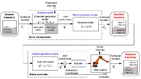
Since the manipulator deflection caused by the loading is known, it can be used to improve the positioning accuracy by means of error compensation technique (Fig. 1). However in practice, only geometrical parameters are provided by the ro-bot manufacturer, while elastostatic parameters should be identified using dedicat-ed calibration techniques. Usually the force-deflection relation (1) is rearrangdedicat-ed in the linear model suitable for the identification procedure, which is a linear map-ping between the parameters to be identified and the end-effector displacement
1 1 ,...
; T , T ( 1, )
i i i i i i ni ni i i m
t A k A J J F J J F (2)
where the vector k collects elastostatic parameters of the matrix 1
θ θ
k K .
It should be mentioned that such a model can be efficiently applied for strictly serial manipulators (without closed-loops) while for heavy manipulators with a gravity compensator this procedure should be revised in order to take into account particularities of the stiffness model. Another difficulty here is related to the gravi-ty compensator modeling, whose parameters are usually not given.
Fig. 1 Off-line compliance errors compensation strategy
Hence, the goal of this work is to obtain a sophisticated elastostatic model that can be used for compliance errors compensation. Accordingly, two problems should be considered: (i) developing the model for the compensator and metho-dology for the identification of its parameters; (ii) integration of the compensator into conventional elastostatic model and identification of its parameters.
3
Parameters of the enhanced manipulator model and their
identification
Considered industrial robot KUKA KR-270 incorporates gravity compensator that is used to balance link-weights but also affects manipulator elastostatic prop-erties. The mechanical structure of the gravity compensator under study is pre-sented in Fig. 2. The compensator incorporates a passive spring attached to the first and second links, which creates a closed loop that generates the torque ap-plied to the second joint of the manipulator. The compensator geometrical model includes three node points P0, P1, P2, which yield three principal geometrical
pa-rameters L P P1, 2 , a P P0, 2 , s P P0, 1 . Let us also introduce some auxiliary
parameters (such as a and x a ), whose geometrical meaning is described in y
Fig. 2. The fact that the gravity compensator affects on the second joint only al-lows us to replace the constant parameter
2
K in the model (1) by the non-linear
one that also takes into account elasto-static properties of the compensator. The variable s describing the compensator spring deflection can be computed as the function of second joint coordinate q2 as follows:
2 2 2
2
cos( ) 2
4 A.Klimchik, Y.Wu, S, Caro, B. Furet, A. Pashkevich
Fig. 2 Gravity compensator and its model
Therefore, the equivalent stiffness of the second joint (comprising both the mani-pulator and compensator stiffnesses) can be expressed as
2 2 0 0 2 2 2 2 2 sin ( ) cos( ) cos( ) c s a L L q q K K K a q s s (4)
where Kc is the gravity compensator stiffness, the value s0 corresponds to the
distance P P0, 1 for the unloaded spring. This allows us to extend the classical
stiffness model (1) of the serial manipulator by modifying the virtual spring para-meters in accordance with the compensator properties. In this case, the Cartesian stiffness matrix KC can be computed using following expression
1 1 T C θ·( θ( ) θθ) · θ K J K q H J (5)which includes both the first and second order derivatives (Jacobians and Hes-sians) of the functions g q θ
, describing the manipulator geometry ((Pashkevichet al. 2011)). Here, the vectors q and θ collect actuator coordinates and the
cor-responding deflections.
The equivalent stiffness of the second joint (4) depends on several geometrical parameters ( , ,L a a ) that are unknown and should be identified using reference x y
points illustrated in Fig. 2b. Taking into account particularities of the experimental setup for the geometric parameters identification, where for each measurement of the point P1 joint coordinate q2 is given, the value of L can be computed as
1 1 m T T i i i i i m i L
p R u
u u (6) where 1 1 m i i m i i
p p p , 1 1 m i i m i i
u u u , [cos , sin , 0]T i qi qi u , pi isthe Cartesian coordinate vector of point P1 for the ith measurement and m is the
number of measurements and the orthogonal matrix RV U can be obtained T
using the following SVD-factorization
1 m i i T i
u p U Σ V . The remaininggeo-metrical parameters (a and x a ) are x and y coordinates of the vector y
1 1 1 1 1 1 1 1 1 0 1 2 k m k m k m j j j j j i i i i i j i j T i i i j i T T s k m
p I n n p p p n n p (7)where 1 1 m j j j i i m l l
p p p , 1 1 m j j j j j i i i l i i T T s p p m
p p , j i p is the Cartesiancoordinate vector of point P0j for the ith measurement, k is the number of
refer-ence points and m is the number of measurements. Here, the vector n is the last
column of the matrix V of the following SVD-factorization
1 1 k m j j i i j i T T
p p U Σ V .Since all geometrical parameters are known, the elastostatic ones can be identi-fied. To take into account the compensator influence while retaining the approach developed for serial robots without compensators, manipulator elastostatic para-meters can be identified into two steps. The first step aims to compute the ex-tended set of elastic parameters that includes all equivalent virtual springs for the second joint by using the standard least-square technique
1 ( ) ( ) ( ) 1 1 · T T m m p p p i i i i i i
k B B B p (8)where the vector pi is the small displacement of the end-effector under the
ex-ternal loading Fi, matrix ( )p i
B is a rearranged matrix A that integrates positional i
components only and takes into account structure of the vector k. The second
step deals with the identification of the gravity compensator parameters and com-pliance of joint #2 that can be obtained from the following equation
2 2 1 0 0 1 1 · q q i T c c i m T m T i i i i K K s K K
C C
C (9)where m is the number of different angles q q2 in the experimental data,
2 2
2 2 2
cos sin cos
1 · / · / ·
i aL qi aL s a L s qi qi
C (10)
In order to ensure high calibration efficiency, the design of experiments should be considered while choosing measurement configurations. To the best of our knowledge, the best results for particular industrial applications can be achieved by using the test-pose based approach (Klimchik et al. 2012b), which reduces op-timal pose selection to the following optimization problem:
1 ( ) ( ) 0 1 0 { , } ( ) ( ) 1 trace q T T min i i m j p j p i p p j i m i A
A A A q w (10) Here matrix ( ) 0 pA has the same structure as matrix ( )p i
A , but is defined by the
desired test pose configuration q0 and the external loading F0. The values of q0,
0
F are usually related to a typical machining configuration and force generated by
the tool-workpiece interaction. Such an approach allows us to ensure the highest positioning accuracy after compensation compliance errors caused by the technol-ogical process.
Using theoretical results presented in this section, it is possible to obtain a so-phisticated elasto-static model that can be used for further error compensation. In the next section, these results are used to obtain the stiffness model of the KUKA KR-270 robot.
6 A.Klimchik, Y.Wu, S, Caro, B. Furet, A. Pashkevich
4
Experimental results and comparison analysis
The main geometric parameters of the gravity compensator are L, ax and ay (see
Figure 2). They can be identified by using relative locations of points P0 and P1
with respect to point P2. Since the adopted geometric model is a planar one, here
the laser tracker base frame is defined in a particular way in order to ensure that the marker locations relative to the XY-plane are not significant. Another impor-tant issue is related to the selection of the marker point locations on the rigid part of the gravity compensator. To ensure high identification accuracy, these markers should be located on the opposite sides of the compensator rotational axis, such that the optimal conditions
1 cos 0 k j j R j
and 1 sin 0 k j j R j
are satis-fied. To increase the identification accuracy, four marker points are used in the ca-libration experiments and are denoted as P01, P02, P03 and P04 respectively. Theirlocations are presented in Fig. 1, where the radii R1R3 and R2R4, and the
angles 3 1 and 4 2. The measurement data have been obtained using laser-tracer Leica for the set q2
0 , 30 , 60 , 90 , 120 , 140
. Thevalues of the identified geometrical parameters and corresponding confidence in-tervals are given in Table 1.
Table 1. Identification results for the compensator geometric parameters
L [mm] ax [mm] ay [mm]
Value 184.72 685.93 123.30
CI ±0.06 ±0.70 ±0.69
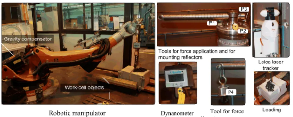
For the identification of manipulator elastostatic parameters, 15 measurement configurations (with 5 different values of q2) were obtained based on the proposed
industry oriented performance measure (10), for which the position coordinates of the reference points (P1, P2 and P3) were measured three times (before and after
the loading). The corresponding experimental setup is illustrated in Fig. 3. The de-sired elastostatic parameters have been obtained using a two-step identification procedure. On the first step, the base and tool transformations have been com-puted. On the second step, all measurement data as well as the obtained base and tool transformations have been used for the identification of the manipulator elas-tostatic parameters. Corresponding numerical results are given in Table 2.
Table 2. Manipulator elastostatic parameters obtained using different approaches, [µrad/Nm] 1
k k 2 k 3 k 4 k 5 k 6
The results
obtained in this work 0.623
-145° 0.297 0.278 -95° -45° 0° 0.416 2.786 3.483 2.074 (Dumas et al. 2011) 3.798 0.248 0.276 1.975 2.286 3.457
Fig. 3 Experimental setup for manipulator elastostatic calibration
To show the advantages of the developed approach, the manipulator accuracy after calibration has been compared for two distinct plans of calibration experi-ments. The first one has been obtained using the industry-oriented performance measure and implements enhanced numerical routines. In this case, the manipula-tor was presented as a quasi-serial chain, and the calibration data were obtained using the enhanced partial pose measurements. The second plan used measure-ment configurations that were selected semi-intuitively, in accordance with some kinematic performance measures (Dumas et al. 2011). A relevant manipulator model corresponding to the strict serial architecture, and the calibration data were obtained using conventional full-pose measurements.
Using these two sets of calibration data, the identification yielded two slightly different sets of manipulator parameters (Table 2). Then, the obtained parameters (both sets) may be used to compute the end-effector positions for the validation configurations (that were not used in both identification routines). Comparing these results with the corresponding position measurements, it is possible to eva-luate the "calibration quality" and relevant plans of the experiments.
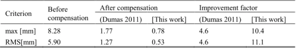
For comparison purposes, the manipulator accuracy improvement due to elas-tostatic errors compensation has been studied based on the error analysis before and after compensation. Relevant results are shown in Table 3, where the maxi-mum and RMS values of the distance-based residuals are provided. As follows from the obtained results, using the identified elastostatic parameters, it is possible to compensate 91.2% of the end-effector deflections (in average). In general, the manipulator positioning accuracy has been improved by a factor of 11.1 compare to a non-compensated robot. Compare to the previous results, the compensation efficiency has been increased by a factor of 2.4 using almost the same number of configurations, which is also referred to as the accuracy improvement factor. Hence, the above presented analysis shows the advantages of theoretical contribu-tions presented in this work. The developed calibration technique allows us to in-crease essentially the manipulator positioning accuracy under external loading us-ing a reasonable number of measurement configurations. It should be noted that the obtained elastostatic parameters can be used for elaso-dynamic analysis also.
8 A.Klimchik, Y.Wu, S, Caro, B. Furet, A. Pashkevich
Table 3. The manipulator accuracy improvement after elastostatic error compensation. Criterion Before
compensation
After compensation Improvement factor
(Dumas 2011) [This work] (Dumas 2011) [This work]
max [mm] 8.28 1.77 0.78 4.6 10.4
RMS[mm] 5.90 1.27 0.53 4.6 11.1
5
Conclusion
The paper deals with the accuracy improvement of a heavy industrial robot employed in milling. It provides a sophisticated geometric/elastostatic model for quasi serial manipulator with gravity compensator and techniques for the identifi-cation of the model parameters. In order to improve the identifiidentifi-cation accuracy, design of experiments technique based on industry oriented performance measure was used. The advantages and practical significance of the proposed approach have been shown by experimental results and a comparison analysis. The im-provement factor is about 2.4.
Acknowledgements
The work presented in this paper was partially funded by the ANR (Project ANR-2010-SEGI-003-02-COROUSSO), France and FEDER ROBOTEX, France.
References
Dumas, C., Caro S., Garnier S. and Furet B. (2011). Joint stiffness identification of six-revolute industrial serial robots. Robotics and Computer-Integrated Manufacturing 27(4): 881-888.
Klimchik, A., Bondarenko D., Pashkevich A., Briot S. and Furet B. (2012a). Compensation of Tool Deflection in Robotic-based Milling. ICINCO 2012: 113-122.
Klimchik, A., Wu Y., Pashkevich A., Caro S. and Furet B. (2012b). Optimal Selection of Measurement Configurations for Stiffness Model Calibration of Anthropomorphic Ma-nipulators. Applied Mechanics and Materials 162: 161-170.
Kövecses, J. and Angeles J. (2007). The stiffness matrix in elastically articulated rigid-body systems. Multibody System Dynamics 18(2): 169-184.
Merlet, J.-P. and Gosselin C. (2008). Parallel Mechanisms and Robots. Springer Handbook of Robotics. B. Siciliano and O. Khatib, Springer Berlin Heidelberg: 269-285.
Pashkevich, A., Klimchik A. and Chablat D. (2011). Enhanced stiffness modeling of mani-pulators with passive joints. Mechanism and machine theory 46(5): 662-679.
Salisbury, J. K. (1980). Active stiffness control of a manipulator in Cartesian coordinates. Decision and Control including the Symposium on Adaptive Processes, IEEE: 95-100.
![Table 2. Manipulator elastostatic parameters obtained using different approaches, [µrad/Nm]](https://thumb-eu.123doks.com/thumbv2/123doknet/7795509.260462/7.892.189.704.878.1007/table-manipulator-elastostatic-parameters-obtained-using-different-approaches.webp)