HAL Id: hal-01388745
https://hal.archives-ouvertes.fr/hal-01388745
Submitted on 2 Nov 2016
HAL is a multi-disciplinary open access
archive for the deposit and dissemination of
sci-entific research documents, whether they are
pub-lished or not. The documents may come from
teaching and research institutions in France or
abroad, or from public or private research centers.
L’archive ouverte pluridisciplinaire HAL, est
destinée au dépôt et à la diffusion de documents
scientifiques de niveau recherche, publiés ou non,
émanant des établissements d’enseignement et de
recherche français ou étrangers, des laboratoires
publics ou privés.
Comparison of two position and speed estimation
techniques used in PMSM sensorless vector control
Driss Yousfi, Abdallah Darkawi
To cite this version:
Driss Yousfi, Abdallah Darkawi. Comparison of two position and speed estimation techniques used in
PMSM sensorless vector control. 4th IET International Conference on Power Electronics, Machines
and Drives (PEMD 2008), Apr 2008, York, United Kingdom. pp.626-630, �10.1049/cp:20080597�.
�hal-01388745�
Comparison of two Position and Speed Estimation Techniques
used in PMSM Sensorless Vector Control
Driss Yousfi, Member, IEEE, Abdallah Darkawi
Ecole Nationale des Sciences Appliquées - Marrakech
MESESYP Laboratory, Control Systems, Power Electronics and Electric Dives Group Avenue Abdelkrim Elkhattabi, B.P. 575 Guéliz, Marrakech
Tel: +212 24 43 47 45 / 46, Fax: +212 24 43 47 40. Email: [email protected]
Keywords: PMSM vector control, sensorless, flux estimator,
reduced observer, comparative study.
Abstract
The paper describes the comparison between two different high-performance techniques used for the sensorless estimation of the motor shaft position in Permanent Magnet Synchronous Motor Sensorless Drives.
Rotor position and speed are estimated from measured terminal voltages and currents, and are used as feedback in a sensorless vector control scheme, achieving almost the same high-performance of a sensored drive.
The paper point out the differences, by using experimental implementation, between an open-loop flux estimator based on the electrical model of the machine, and a reduced flux observer.
1 Introduction
Vector controlled Permancnt Magnet Synchronous Motor (PMSM) need an encoder or a resolver to correctly align the stator current vector. Such an electromechanical position transducer is not present in DC motor drives or in constant V/Hz induction motor drives, thus disadvantaging PMSM drives in medium and low power applications.
To overcome this weakness, several sensorless strategies for PMSM vector control, based on different position and speed estimation techniques have been proposed in last years [1]. Generally, they consist of processing stator voltage and current measurements to perform the sensorless estimation of the mechanical quantities
Among the proposals in this field, two kinds of approaches seem to be most interesting since they do not need any additional hardware i.e. the electrical model based techniques [8] and the state observer based techniques [2-5].
From the two mentioned families, the paper consider precisely:
− An open-loop electrical model based flux estimator that was developed in our laboratory [11].
− A reduced flux observer which is derived from an existing full order Luenberger observer [6,7], and improved to achieve good performance.
The paper, then, wants to compare the two methods in terms of:
• Complexity of the method.
• Position and speed estimation performance.
• Sensorless speed range.
• Immunity against motor parameters uncertainty and electrical measurement errors.
• Initial position error cancellation.
2 Modeling of the PMSM
In this section, a brief description of the PMSM mathematical models are described since both the investigated estimation methods need to manipulate the equations of the machine. The models of the PMSM in the stationary frame (α-β) and the rotating frame (d-q) are respectively:
dt d i R v dt d i R v β β β α α α Φ Φ + = + = (1) ) sin( i L ) cos( i L m m θ Φ Φ θ Φ Φ β β β α α α + = + = (2) ,and d q q q q d d d w dt d i R v w dt d i R v Φ Φ Φ Φ + + = − + = (3) q q q m d d d i L i L = + = Φ Φ Φ (4)
,where Φm is the maximum phase flux linkage of the
permanent magnet, Lαβ and Ldq the inductances in αβ and dq
frames, R the winding resistance and θ the actual rotor angle. These models form the basis for the presented rotor position and speed estimator. As the considered PMSM is a non-salient machine, all the inductances in those equations are equal .i.e. Lα=Lβ=Ld=Lq=L.
3 Open-loop Flux Estimator Based Technique
Position sensing via flux-linkage variation has been known for many years, but its successful implementation has become possible only in the last decade with the emergence of devices with sufficient real-time processing power.
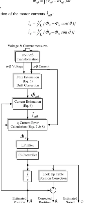
The first investigated technique belongs to this category of estimators. It is based on an open-loop flux linkage estimation and PI-controller. Accurate flux linkages are derived from the back-emf by means of a modified integrator. The estimation algorithm is schematically illustrated in Fig. 1 and involves the following steps [8]:
Step 1:
Estimation of the flux linkage in αβ-frame by measuring the phase voltages and currents:
∫
− = (v Ri )dt ˆ αβ αβ αβ Φ (5) Step 2:Estimation of the motor currents iˆαβ:
)] ˆ sin( ˆ [ L 1 iˆ )] ˆ cos( ˆ [ L 1 iˆ m m θ Φ Φ θ Φ Φ β β α α − = − = (6)
Fig. 1: Flowchart of the position and speed estimator.
Step 3:
Calculation of the difference between the actual currents and the estimated ones in α-β and d-q frames using the Park transformation: αβ αβ αβ ∆i =i −iˆ (7) ) ˆ cos( i ) ˆ sin( i iq ∆ θ ∆ θ ∆ =− α + β (8)
This last current error is passed through a Low Pass filter to reduce the effect of the noise due to the differentiation.
Step 4:
Finally, a PI-Controller is used to cancel the obtained error by accelerating or decelerating the dˆ−qˆ frame. Thus, the PI- Controller output is the estimated speed wˆ .
The position estimate θˆ can be deduced through an integration and corrected using Look Up Table procedure that gives a correction term ∆θ; so:
θ ∆ θ θˆ = ˆ+
c (9)
4 Reduced Flux Observer Based Technique
State observers require the use of a relatively accurate motor model, the measurement of the motor currents (system output) and the knowledge of the feeding voltages (system input). The basic idea is to use the difference between the state variables and the estimated state variables to calculate the rotor position and speed, directly or through related variables. Several sort of approaches are reported in literature i.e. deterministic (Luenberger [2,3]), non-linear (sliding mode [4]) and stochastic (extended Kalman filters [5]) observers. They exhibit different peculiarities in term of algorithm complexity and sensitivity to parameter variation and noise. The used observer is based on the flux linkage model of the PMSM in a two phase stationary frame as shown in the following equation: Cx y Bu Ax x = + = & (10) where − − − = 0 w 0 0 w 0 0 0 0 0 0 0 A e e γ γ γ γ , = 0 0 0 0 1 0 0 1 B and − − = L 1 0 L 1 0 0 L 1 0 L 1 C (11)
The input vector and the full state vector are respectively:
T
u=vα vβ and x= Φ α Φβ Φmα Φmβ . T
The aimed states are: Φ = Φmα mcosθe and Φ = Φmβ msinθe. The output vector is the measured currents: y=iα iβT.
α-β Voltage α-β Current Estimated Position Corrected Position Estimated Speed αβ
Φ
ˆ
αβiˆ
qi
∆
Voltage & Current measures
wˆ θˆ θˆc Look Up Table Position Correction + Flux Estimation (Eq. 5) Drift Correction q-Current Error Calculation (Eqs. 7 & 8)
Current Estimation (Eq. 6) PI-Controller s 1 LP Filter ,abc / αβ, Transformation
In the state space model we and θe are the electrical rotor
speed and position. γ = R / L is the inverse of the time constant.
To consider the reduced version of the above observer a reduced vector and matrix are introduced as follow:
A11 = J w , A12 = [0], A21 = γ I, A22 = −γ I, B1 = [0], B1=I (12) T m m v x y α β α β = Φ Φ Φ Φ = M ,where m m v α β Φ =Φ and y α β Φ =Φ − = = 0 1 1 0 J and 1 0 0 1 I
If z= −v Gyˆ , z the reduced observer is defined by:
[
]
y G z vˆ u ) B G B ( y A G A G ) A G A ( z ) A G A ( z r 2 r 1 22 r 12 r 21 r 11 21 r 11 + = − + − + − + − = & (13)ˆ
v
is the estimate state and Gr is the reduced observer gainand is defined by : 1 2 1 2 2 1 r g g G g I g J g g − = = + (14)
Supposing the mechanical quantities slowly changing versus the electrical ones, the model can be then considered as a linear time varying system. Now with appropriate calculation of the matrixes Gr, B0 and K0 the state error continually
vanishes. The rotor position estimation is calculated by the arctg operation: Φ Φ = θ α β m m ˆ ˆ tan Arc ˆ (15)
Fig. 2 shows the resulting observer scheme.
It is clear from the state equations (10,11) that rotor speed is required first for the implementation of the flux observer. A simple manner to estimate its magnitude is given by [6]:
m 2 2 e e wˆ ψ δ β α+ ≈ (16) Here, δ is an adjustment coefficient.
5 Experimental Results
The general block schematic of the laboratory setup used for experimental verification is shown in Fig. 3. It consists of a 500W three-pole PMSM which is fed by an IGBT Voltage Source Inverter. For estimation and control tasks, a dSpace DS1104 board has been used. In order to compare the estimated position and speed signals with the actual output, an incremental encoder is also mounted on the drive shaft.
Fig. 2. Block diagram of the reduced position observer.
Fig. 3. Sensorless control with Position and Speed Estimator.
∫ + vαβ iαβ +
y
ˆ
v
θˆe L + Arctg Ko Gr eω
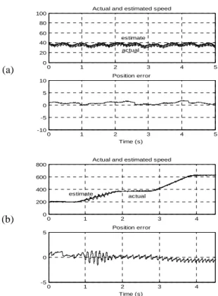
Bo F=A11 - GrA21The sensorless PMSM drive is demonstrated to operate in satisfactory manner with the two elaborated techniques:
1. Open-loop flux estimator based technique Fig. 4.
2. Reduced flux observer based technique Fig. 5.
The tests are accomplished with correction procedures. The figures show the speed estimates (in rpm) and the position errors (in deg): in low speed operation (a) and in varying speed and considerable load conditions (b).
The positional error is measured to be within +/-1.5° in all conditions for the first method and +/-1° for the second. A minor prior adjustment is necessary to allow initial position error cancellation in open-loop flux estimator based technique.
6 Results Analysis and Comparison
When the mechanical sensor is replaced by an estimation technique that provides the rotor position and speed, all the control methods commonly used in sensored control of the motor are conserved in the sensorless scheme. That is the major advantage shared by the presented sensorless techniques.
On the other hand, the major difference between the two techniques results from the flux estimation which is carried out by an open-loop calculation in the first method and by a closed-loop one in the second method. So, the flux observer based technique is a self-adjusting flux estimation method. In the following section the effects of different factors on the rotor position and speed estimation accuracy are investigated.
6.1 Starting up
Starting difficulty is a challenging problem in sensorless operation of PMSM drives. For consistent starting, a separate technique was needed, often using the inductance-variation approach [9] or the high frequency signal injection [10,11]. In fact, a closed loop smooth and reliable starting can only be achieved when information regarding the absolute rotor position is available.
For a simple starting, the test motor is started up in open-loop operation as a stepper motor with sinus-wave excitation until the rotor speed reaches convenient level for angle estimation. The lowest sensorless speed is 25 rpm for the first technique and 33 rpm for the second.
6.2 Speed Estimation
As described in section 3 the rotor speed, in the open-loop flux estimation based method, is obtained by closed-loop estimation using PI-Controller. That is the reason of the good estimation results of this quantity (Fig. 4).
However, in the observer estimation technique, the speed is estimated separately and it is considered to be a system parameter (11). Therefore the position estimation accuracy is dependent on the accuracy of the speed estimate, which depends itself on the PM flux linkage Φm (16).
Not including an adaptive correction scheme, PM flux linkage uncertainty would generate velocity estimation error, particularly in low speed rang. As, in such condition the
back-emf signals derived from the measured current and voltage are feeble. Additional procedure is then necessary to remove the effects of this uncertainty.
6.3 Effect of Resistance Uncertainty:
In the PMSM, the most temperature sensitive parameter is the stator winding resistance, the fundamental parameter necessary for all the presented techniques. The effect of an uncertainty at the level of this parameter introduces a steady rotor angle estimation error. If the stator current is in phase with the motional back-emf, uncertainty in the stator resistance generates no error in the estimated rotor angle [7].
6.4 Effect of Stator Voltage and Current Measurement Errors
Both the indirect position sensing methods require the measurement of the stator current and voltage waveforms. The use of these measurements in the rotor position estimator will result in angle estimation inaccuracy owing to the inevitable scaling or offset errors contained in the sensed quantities.
In practice, the open-loop integration in (5) is prone to errors caused by drift. Small offset signals in the measurements are summed over time, causing the integrator output to saturate. Furthermore, an initial value problem associated with the pure integrator occurs from the integral value at the initial instant. Integrator drift can be reduced by improving the pure integrator with a low-pass filter with very low cutoff frequency. Another way to solve this problem consists in replacing the integrator by an alternative integrator structure [8,12]. But these modifications have two drawbacks: the inhibition of the flux estimator in low-speed range and the phase lags induced by the filter. Consequently an additional position error arises.
Based on the above considerations, a Look Up Table procedure is implemented to compensate the position estimation error. The estimation algorithm becomes then more complicated.
In the second technique, selecting the magnitude of the closed-loop eigenvalue reals to be much greater than the angular velocity helps to reduce the effect of voltage measurement offsets on the rotor position estimation accuracy.
7 Conclusion
When the presented estimation methods are compared in their complete version, the reduced flux observer based technique seems more complex in term of formulation and practical implementation. But in actual fact, the closed-loop flux estimation achieved by this technique makes it more attractive; especially if the problem of the speed estimation in low speed rang is resolved by using a position derivation instead of the back-emf based calculation. Furthermore, with appropriate parameters adjusting the observer based technique presents a good immunity against motor parameters uncertainty and electrical measurement defaults.
Basically, the main limitations of the investigated solutions refer to standstill operation and safe starting due to the unobservability of rotor angle under those operating conditions. In many industry applications, initial positioning is not necessary and a simple open-loop starting up can be used. In the opposite case, starting method should be involved in the whole sensorless algorithm.
References
[1] J.P. Johnson, M. Ehsani and Y. Guzelgunler, “Review of sensorless methods for brushless DC,” Proc. IEEE Ind. Appl. Soc. Annu. Meeting, St. Louis, MO, Oct. 1999, vol. A, pp. 143–150.
[2] P. Pillay and R. Krishnan, “Application characteristics of permanent magnet synchronous and brushless DC motors for servo drives,” IEEE Trans. Ind. Appl., vol. 27, no. 5, pp. 986– 996, Sep./Oct. 1991.
[3] S. K. Safi, P. P. Acarnley, and A. G. Jack, “Analysis and simulation of the high-speed torque performance of brushless DC motor drives,” Proc. Inst. Elect. Eng.—Electr. Power Appl., vol. 142, no. 3, pp. 191–200, Mar. 1995.
[4] H.-C. Chen and C.-M. Liaw, “Current-mode control for sensorless BDCM drive with intelligent commutation tuning,” IEEE Trans. Power Electron., vol. 17, no. 5, pp. 747–756, Sep. 2002.
[5] K.-Y. Cheng and Y.-Y. Tzou, “Design of a sensorless commutation IC for BLDC motors,” IEEE Trans. Power Electron., vol. 18, no. 6, pp. 1365–1375, Nov. 2003.
[6] T.D. Batzel and K. Y. Lee, “Electric propulsion with the sensorless permanent magnet synchronous motor: model and approach,” IEEE Trans. Energy Convers., vol. 20, no. 4, pp. 818–825, Dec. 2005.
[7] T.D. Batzel and K. Y. Lee, “Electric Propulsion With Sensorless Permanent Magnet Synchronous Motor: Implementation and Performance,” IEEE Trans. Energy Convers., vol. 20, no. 3, pp. 575–583, Sept. 2005.
[8] D. Yousfi and M. El Adnani, “Indirect Position and Speed Sensing for PMSM Sensorless Control,” Proc. 7th International Conference on Power Electronics (ICPE '07)’, Daegu-Korea, Oct. 2007.
[9] T. Takeshita, A. Usui, and N. Matsui, “Sensorless salient-pole PM synchronous motor drive in all speed ranges,” Electr. Eng. Jpn., vol. 135,
no. 3, pp. 64–73, 2001.
[10] M. J. Corley and R. D. Lorenz, “Rotor position and velocity estimation for a salient-pole permanent magnet synchronous machine at standstill
and high speeds,” IEEE Trans. Ind. Applicat., vol. 34, pp. 784–789, July/Aug. 1998.
[11] L. A. S. Ribeiro et al., “Comparision of carrier signal voltage and current injection for the estimation of flux angle and rotor position,” in Proc. IEEE Industrial Applications Soc. Annu. Meeting, St. Louis, MO, Oct. 1999, pp. 452–459. [12] J. Hu and B. Wu, “New integration algorithms for estimating motor flux over a wide speed range,” IEEE Trans. Power Electron., vol. 13, no. 5, pp. 969–977, Sep. 1998.
(a) (a) (b) 0 1 2 3 4 5 6 7 0 50 100 150
200 Actual and estimated speed (rpm)
0 1 2 3 4 5 6 7
-10 -5 0 5
10 Position error (deg)
Time (s) estimate actual 0 1 2 3 4 5 400 600 800 1000 1200
1400 Actual and estimated speeds
0 1 2 3 4 5 -5 0 5 Position error Time (s) estimate actual (b) 0 1 2 3 4 5 0 20 40 60 80
100 Actual and estimated speed
0 1 2 3 4 5 -10 -5 0 5 10 Position error Time (s) estimate actual 0 1 2 3 4 0 200 400 600
800 Actual and estimated speed
0 1 2 3 4 -5 0 5 Position error Time (s) estimate actual
Fig. 4. Experimental results of the open-loop flux estimator based technique.
Fig. 5. Experimental results of the reduced flux observer based technique.