Construction Based Design
by
Kevin M. Westerhoff
B.S. Civil & Environmental Engineering Lehigh University, 2000
SUBMITTED TO THE DEPARTMENT OF CIVIL & ENVIRONMENTAL ENGINEERING IN PARTIAL FUFILLMENT OF THE REQUIRMENTS OF THE DEGREE OF MASTER OF ENGINEERING IN CIVIL AND ENVIRONMENTAL ENGINEERING
AT THE
MASSACHUSETTS INSTITUTE OF TECHNOLOGY JUNE 2002
© 2002 Kevin M. Westerhoff All rights reserved
The author hereby grants to MIT permission to reproduce and to distribute publicly paper and electronic copies of this thesis document in whole or in part.
//I-Jy Signature of Author: Certified by: Accepted by: MASSACHUSETTS INSTITUTE OF TECHNOLOGY
JUN
3 2002
LIBRARIES-Department of Civil & Environmental Engineering May 10, 2002
Jerome J. Connor Professor of Civil & Environmental Engineering Thesis Supervisor
Oral Buyukozturk Professor of Civil & Environmental Engineering Chairman, Committee for Graduate Students BARKER
Construction Based Design
byKevin M. Westerhoff
Submitted to the Department of Civil and Environmental Engineering on May 10h , 2002 in Partial Fulfillment of the
Requirements for the Degree of Master of Engineering in Civil and Environmental Engineering
ABSTRACT
This thesis studies the evolution of a project's design and its relationship to construction sequencing. In recent years, the advantages of the design/build project delivery method have become evident with respect to both cost effectiveness and design efficiency. As a designer, the question of how a project should be approached within this context in its beginning stages arises in order to make the most effective use of valuable resources. In order to facilitate the selection of an optimum design solution within this context that balances the requirements of the design with the constraints of construction, a set of guidelines is developed. These guidelines are then used to select one of three proposed design solutions for a case study of an elevated restaurant structure supported by twin braced arches which is a part of a new baseball park for the Boston Red Sox. To help develop these guidelines, various types of bridges are presented as examples
with respect to their design and construction. Bridges have been chosen as examples as they help to illustrate the distinct relationship that exists between design and construction. This study is done in the context of a design/build project as it provides the best environment in which to foster these ideas.
Thesis Supervisor: Jerome J. Connor
Acknowledgements - 5
Acknowledgements
I would like to extend my sincere thanks to the following people in helping not only with the completion of this thesis, but also in making my experience here at MIT invaluable and much more enjoyable.
" Lisa Grebner of Modem Continental Construction for the sharing of her time and knowledge; especially in developing and editing this thesis.
* Paul Kassabian not only for his help and patience in creating Chapter Four: The Gateshead Millennium Bridge, but also his help, advice, and friendship
throughout the year.
" Prof. Jerome Connor for his guidance and excellent teaching that has helped to make the past nine months so successful.
" The 2002 High Performance Structures Group not only for their hard work and enthusiasm that helped to make our project such a success, but also for their friendship and help in making it through the past nine months.
I would also like to thank Leonard Belliveau, William Campbell, and Joubin Hassanein of Modem Continental Construction for the sharing of their time and valuable knowledge on the C19B 1 contract of the Central Artery Tunnel.
Finally, I would especially like to thank both my father Richard V. Westerhoff, SB 1957, and grandfather Russell P. Westerhoff, SB 1927, SM 1928, for having provided the foundations and inspiration for all which I have achieved and have yet to in the future.
Table of Contents - 7
Table of Contents
Title Page 1 Abstract 3 Acknowledgements 5 Table of Contents 7 List of Figures 11CHAPTER 1
Introduction 15 1.1 Motivation 151.2 The Design Build Methodology 16 1.3 Introduction of Project 17
CHAPTER 2
Bridge Design & Construction 21 2.1 Introduction 21
2.2 Suspension Bridges 22 2.3 Cable Stay Bridges 25 2.4 Arch Bridges 28
2.5 Balanced Cantilever Girder Bridges 30 2.6 Span-by-Span Constructed Bridges 32 2.7 Summary 33
CHAPTER 3
-
Case Study: Segmental Bridges
The Central Artery Tunnel Project C19B1 Contract 35 3.1 Project Overview 35
3.2 Launch Gantry Method 38 3.3 Balanced Cantilever Method 41 3.4 Design Adjustments 44
3.5 Comparison of Methods 46 3.6 Summary 47
CHAPTER 4
-
Case Study: Special Structures
The Gateshead Millennium Bridge 514.1 Project Overview 51 4.2 Project Evolution 52
4.3 Construction Sequencing 53
4.4 Structural Design & Modifications 55 4.5 Summary 59
CHAPTER
5
Design Parameters of Restaurant 61 5.1 Architectural Layout 61 5.2 Load Distribution 62 5.3 Design Code 63 5.4 Construction 64
CHAPTER 6
Sequence One 65 6.1 Design Approach 65 6.2 Structural System 65 6.3 Construction Sequence 75CHAPTER
7
Sequence Two 77 7.1 Design Approach 77 7.2 Design Modifications 77 7.3 Construction Sequence 78CHAPTER 8
Sequence Three 838.1 Introduction & Conceptualization 83 8.2 The Model 87 8.3 Serviceability 90
CHAPTER 9
Conclusions 95 9.1 Basis of Comparison 95 9.2 Comparison of Sequences 96 Works Cited 103Appendix A
Design Calculations for Sequence One and Two 105 A.1 Composite Floor 105
A.2 Floor Joists 112
A.3 Main Floor Beams 113 A.4 Outer Ring Beam 114
A.5 Outer Floor Support Beam 115 A.6 Hanger Rods 116
A.7 Compression Ring 117
Table of Contents - 9
A.9 Equivalent Stiffness for Cables 120
A.10 Weight Calculations: Construction Purposes (Sequence 2) 122 A. 11 Temporary Steel for Sequence One 123
Appendix B
Sequence Three Design Calculations 125 B.1 Conceptual Schemes 125
B.2 Joist Specification 135 B.3 Loading Cases 138
B.4 Restaurant Dead Load Estimate & Weight Distribution 148 B.5 Effective Cable Stiffnesses 150
B.6 Weight Calculation of Regions for Construction Purposes 151
Appendix C
Modal Analysis & Motion Control (Sequence One & Two) 153 C.1 Narrative 153
C.2 SAP2000 Model 158
C.3 Design of Tuned Mass Damper for Sequences One & Two 160 C.4 Modal Shapes 162
Appendix D
SAP 2000 Input Files 163
D. 1 Sequence One & Two: Main Floor Beams 163 D.2 Sequence One & Two: Outer Ring Beams 169 D.3 Sequence One & Two: Outer Floor 173
D.4 Sequence Two: Temporary Steel 175 D.5 Sequence Three: Phase 2 179
D.6 Sequence Three: Phase 4 187
List of Figures -11
List of Figures
Figure 1.1 - 3D elevation of elevated restaurant and the New Red Sox Baseball Stadium
from the South 17
Figure 1.2 - Site plan view of the stadium project 18
Figure 2.1- MIT HPS Group at Akashi Kaikyo January 30, 2002. Pictured from the
right: Carmen Hundson, Sakda Chaiworawitkul, Marc Steyer, Charisis
Chatigogos, Fiona Kwok, Paul Kassabain, Tzu-Yang Yu, Kyoko Ichikawa, Bora Tokyay, Kevin Westerhoff 22
Figure 2.2- Akashi Kaikyo construction sequence. (Courtesy of Honshu-Shikoku Bridge
Authority) 23
Figure 2.3- Schematic of cable stay bridge system 25
Figure 2.4- Schematic showing erection process of precast concrete segments 26 Figure 2.5 - Arch structural types. (Courtesy of Matsuo Bridge Co. Ltd) 28
Figure 2.6- The first segmentally constructed concrete arch bridge in the U.S., Natchez
Trace Parkway, Franklin Tennessee. (Courtesy of U.S. Department of Transportation) 29
Figure 2.7- Eads Bridge Construction using the cantilever method. (Courtesy of
Columbia University) 30
Figure 2.8 - Typical precast concrete box girder section 31
Figure 2.9 - Launch Gantry at Boston's Central Artery Tunnel Project (Courtesy of the Massachusetts Turnpike Authority) 32
Figure 3.1 - Aerial View of C19B] Project Site (Courtesy of Massachusetts Turnpike Authority) 35
Figure 3.2 - Launch Gantry in action (Courtesy of the Massachusetts Turnpike Authority) 38
Figure 3.3 - Schematic of Launch Gantry System 40
Figure 3.4 - Elevation and plan view of balanced cantilever method 42
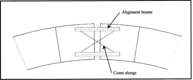
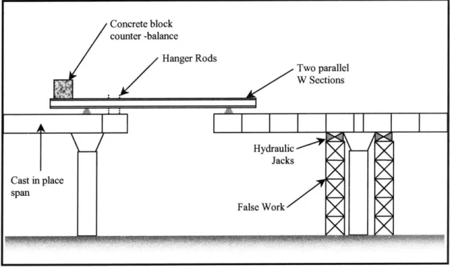
Figure 3.5 - Closure method for balanced cantilever method 43 Figure 3.6 - Modified Balanced Cantilever Method 45
Figure 4.1 - The Gateshead Millennium Bridge (Courtesy of the Gateshead Metropolitan Borough Council) 51
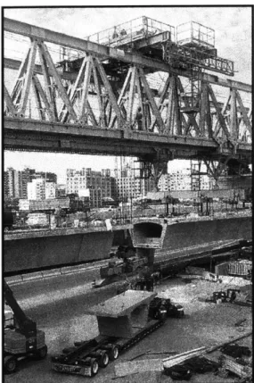
Figure 4.2 - Assembly of the arch and deck at the staging ground. Note the three deck sections to the right of the image. (Courtesy of the Gateshead Metropolitan Borough Council) 53
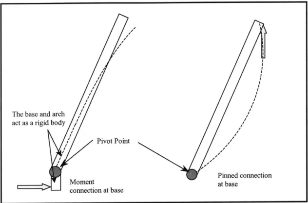
Figure 4.3 - Change in behavior of the arch due to the two different temporary support schemes 56
Figure 4.4 - Cross section views of arch at the lifting lug and a typical cross section 57
Figure 4.5 - Temporary shoring tower repositioned for lifting of assembled bridge (Courtesy of the Gateshead Metropolitan Borough Council) 57
Figure 4.6 - Elevation of bridge deck showing pre-cambers 58
Figure 5.1 - Restaurant Floor Plan 61
Figure 5.2 - Twin braced arch cable support system 61 Figure 5.3 - Restaurant Cross Section showing load path 62 Figure 6.1 - Elevator core with main floor beams positioned 65
Figure 6.2 - Ring Beam 66
Figure 6.3 - Floor Joists 68 Figure 6.4 - Hanger Rods 69
Figure 6.5 - Connection details at ring beam and hanger rods 70 Figure 6.6 - Compression Ring location 71
Figure 6.7 - Compression Ring Details 72
Figure 6.8 - Outer Floor location 72 Figure 6.9- 3D Roof Truss Details 74
Figure 6.10 - Temporary steel orientation with main floor beams and outer ring beam for construction sequence 1 76
Figure 7.1 - Restaurant structural elements assembled at grade 77
Figure 7.2 - Orientation of lifting beams and cables for sequence 1 79
Figure 8.1 - Conceptual schemes for sequence three 83 Figure 8.2 - Structural framing layout of main floor 85
Figure 8.3 - Detail of cable socket connection 86 Figure 8.4 - SAP2000 3D Model of the region 87
List of Figures -13
Figure 8.6 - Erection Sequence for regions 89 Figure 8.7 - 3D view offull SAP model 90
Figure 8.8 - Beam Cambers 92
Figure A.1 - Cross section for cracked moment of inertia calculation 107
Figure A.2 - Cross section for un-cracked moment of inertia 107 Figure A.3 - Concentrated load diagram for composite slab 110
Figure A.4 - Un-cracked movement of inertia for concentrated load 110 Figure A.5 - Uniform loading for joist specification 112
Figure A.6 - Load distribution for model of main floor beam 113 Figure A.7 - Load distribution for model of outer ring beam 114 Figure A.8 - Load distribution for model of outer floor beam 115 Figure A.9 - Model of steel box for the compression ring 117 Figure A.10 - Diagram of steel box for cable socket 119 Figure A.11 - Cable identification from plan view 120
Figure A.12 - Distribution offloor areas for cable stiffness calculation 121
Figure A.13 - SAP2000 Model used to determine the maximum vertical reaction for the
temporary steel. 123
Figure A.14 - SAP2000 model for temporary steel 123 Figure B.1 - Centroid location of region for scheme 1 126 Figure B.2 - Centroid locations of regions for scheme 2 127 Figure B.3 - Centroid locations of regions for scheme 3 129
Figure B.4 - Force diagram for preliminary member sizing of scheme 3 131 Figure B.5 - Force diagram for temporary cable 132
Figure B.6 - Centroid locations of regions for scheme 4 133
Figure B.7 - Uniform load distribution for joist specification: Case 1 135
Figure B.8 - Uniform load distribution for joist specification: Case 2 135
Figure B.9 - Designation of regions 138
Figure B.10 - Section sizes for phase 1 of construction sequence 139 Figure B.11 - Model of temporary construction cable 140
Figure B.12 - Section sizes
for
phase 2 of construction sequence 140 Figure B.13 - Section sizes for phase 3 of construction sequence 141Figure B.14 Figure B.15 Figure B.16 Figure B.17 Figure B.18
- Weight distribution for roof and floor 143 - Unbalanced snow load for convex curved roof
- Asymmetric wind forces on roof 145
- Distribution of wind forces on convex curved roof
- Section sizes for phase 4, service life 146
Figure C.1 - SAP2000 Model showing deflection at the natural frequency 154
Figure C.2 - 3D rendering of TMD attached to main floor beam 156
Figure C.3 - Schematic details of TMD 156
Figure C.4 - Unit cross section of composite floor in transverse direction 158
Figure C.5 - Unit cross section of composite floor in longitudinal direction 158
Figure D.1 - SAP2000 Figure D.2 - SAP2000 Figure D.3 - SAP2000 Figure D.4 - SAP2000 Figure D.5 - SAP2000 Figure D.6 - SAP2000 Figure D.7 - SAP2000 model model model model model model model
of main floor beam 163 of outer ring beam 169
of outer floor beam 173 of temporary steel 175 of region 2 179
of sequence 3 main floor 187
of the main floor of sequence one and two 209 144
Chapter 1: Introduction - 15
Chapter 1
Introduction
§
1.1
- MotivationWith the engineering and construction industry turning more and more to the design/build project delivery method, engineers and constructors are being called upon to develop practical and efficient designs in an interactive environment. The integration of both design and construction of a project leads to a question of optimization of a design solution. The basic premise of design/build projects is to remove the barriers that have existed in the past between design and construction. This allows these two elements of a project to develop together helping to foster a balance between the two.
The intent of this thesis is to develop a set of guidelines or list of considerations that can be used to evaluate the feasibility of a design solution with respect to both design and construction factors. These guidelines will then be used to help select one of three design solutions proposed for a case study of an elevated restaurant structure which is apart of new multi use baseball park facility for the Boston Red Sox. To develop these guidelines, examples are provided, including specific examples, whose structural systems are similar to that of the elevated restaurant. The project will also be viewed in the context of the design/build project delivery method which is gaining wider acceptance in recent years as a practical alternative to the traditional design/bid/build. The design/build project methodology presents an environment where the guidelines that are developed can be applied to ultimately try to create an optimal design solutions. In Section 1.2 following, the idea and benefits of the design build methodology are presented.
§
1.2 - The Design Build Methodology"The emergence of design/build as a popular alternative delivery system is perhaps the most significant trend within the construction industry in the past 20 years. It's the fastest growing method of project delivery in the U.S., and it is even more popular abroad. Quite simply, "design/build" means that a single entity is responsible for both the project's design and its construction. The design/builder may be a single company or it may be a joint venture" (Rizzo, 44). The benefits of design/build construction include (Rizzo, 45):
" Greater participation by the contractor during the design process providing a constructibility review often resulting in a more cost-effective design.
" The ability to conceptualize and to solidify construction costs at an early stage in the design long before detailed design is complete resulting in increased efficiency.
" Communication between the designer and contractor result in a more effective transformation of design into construction reality and a quicker process.
" The owner enjoys single point responsibility. The client does not have to act as referee of disputes between the designer and constructor.
"In the traditional design/bid/build method, the owner/client hires an architect or engineer, who may spend several months creating contract documents. Additional weeks, even months, are spent in a bidding process to hire a general contractor. Each group (the architects, the engineers, and the contractors) must complete its own phase before the next group can proceed" (Rizzo, 45). In addition, the design engineer develops the contract documents to reflect the structure in its final state. The contractor or construction engineer is then responsible for developing a way in which to construct the structure to achieve the final state represented in those contract documents. This process has inherent difficulties and inefficiencies including poor communication between designers and contractors, disputes over design intent, cost and schedule overruns, and poor quality to name a few (Rizzo, 45).
Chapter 1: Introduction - 17
"The design/build method can reduce or even eliminate these problems because responsibility for both design and construction is vested in a single entity. Throughout the life of the project, the owner/client deals directly with a project manager, who heads a team of professionals responsible for the design and construction" (Rizzo 45). It is for this reason that the design/build concept was chosen for the context of this thesis. The benefits of design/build are clear.
§
1.3 - Introduction of ProjectThe elevated restaurant structure design that is detailed in this thesis is only a portion of a proposal for a new baseball park and mixed use facility for the Boston Red Sox Baseball team. The project itself was conceptualized and developed by the High Performance Structures Group of the Master of Engineering Program at MIT. Sufficient information will be provided here to familiarize the reader with the project and how the restaurant relates to it. A comprehensive discussion of the conceptualization and design of this facility can be found in the HPS Project Report 2002 and should be referenced for any further information.
The project is situated on an 11.2 acre site located in South Boston that is currently
Figure 1.1 - 3D elevation of elevated restaurant and the New Red Sox Baseball Stadium from the
South.
owned by Boston land
icnic Area Living Machine
developer Frank
McCourt. Presently the site serves as a parking lot. The proposed stadium itself provides
seating for
approximately 40,000 spectators. In addition to its function as a
baseball park which Elevated Restaurant
would occupy it for the Ow tAsite plan view
82 Major League
Baseball home games a Figure 1.2 - Site plan view of the stadium project.
year, it also offers opportunities for year round generation of revenues as a multiuse facility. Those opportunities include a shopping mall, a below grade parking facility providing 1000 parking spaces, and of course the elevated restaurant. A plan view of the facility is shown in Figure 1.2.
Additional features include a picnic area in center field that will be available for seating during game and open to the public when there are not games or special events. To the north east of the site is what is termed a living machine. Essentially it is a water treatment facility that will be used to purify non-drinking water for reuse in the stadium. Visually, it resembles a greenhouse.
An important note with regard to construction is that the Up/Down construction method was considered. This is where the construction operations are carried out both above and below grade simultaneously. While this increases the cost for excavation, it dramatically reduces the delivery time for the overall project.
Chapter 1: Introduction -19 Specifics of the elevated restaurant will be reviewed in more detail in Chapter five, Design Parameters.
The design/build methodology provides the ideal environment for the application of the guidelines that will be developed from the examples provided and in the design process of the elevated restaurant. These guidelines can serve as a tool for engineers and constructors to achieve the most balanced design solution possible. They will help encourage both parties to consider the advantages and disadvantages of a design alternative from a holistic point of view. It is important to note that these guidelines are not meant to provide clear right and wrong answers for every aspect of a design as each project is unique, bringing with it different combinations of design considerations and constraints. The hope is that regardless of the variability in the design considerations and constraints, designers will be able to use these guidelines to identify the key issues that drive the decision making process apply them in a general sense to all projects.
In what follows, the design and construction considerations for bridges will be presented in the form of examples and specific projects. It is important to note how construction in terms of both sequence and loadings affects the design of each. Once this relationship is established, the following three chapters will describe designs developed for the elevated restaurant. Each design takes a different perspective in terms of how the design is approached and the results provide a contrast by which to apply the guidelines that will be developed.
Chapter 2: Bridge Design & Construction - 21
Chapter 2
Bridge Design & Construction
§
2.1 - IntroductionBridges have been chosen as a context for evaluating the three design sequences developed for the elevated restaurant because their design is driven by construction in almost every circumstance. They also present a better parallel to the restaurant as opposed to a building. This makes them a prime example for the design/build concept. In some instances, more design effort is needed to go into the development of temporary support structures and erection schemes than for the actual bridge itself. This is especially true of the early concrete arch bridges where formwork was designed to allow the bridges to be cast in place. In addition, experience shows that a large bridge is more likely to suffer failure during erection than during its service life (Durkee, 45-2).
Early bridge construction relied on the use of falsework or shoring to allow the bridge itself to be constructed, essentially providing a formwork in which the structure could experience the same loads during construction as it would during its service life (neglecting live loads). However, great deals of inefficiencies exist with this methodology. In urban areas, the disruption of traffic and services below the project can cause economic damage and pose a safety hazard. In deep gorges and rivers or even seas, falsework is not only expensive, but also a safety hazard (Sauvageot, 11-4). These constraints have lead to the development of more efficient and effective methods of construction, such as span by span, balanced cantilever, and cabling construction methods for segmental concrete bridges.
However, there is no free lunch. As these methods have increased efficiencies in construction, they have also increased the structural requirements of the bridge design itself. This means that the designer cannot simply design the bridge for the service loads it will experience and simply hand it off to the contractor for construction. How the
structure is to be built has become an integral part of the design as the governing load conditions have shifted from service loads to construction loads in many cases.
The degree to which the design of bridges is affected by these temporary construction loads varies with the method of construction chosen as well as the type of bridge. Here, we will examine several types of bridges that exemplify this notion of construction based design.
§
2.2 - Suspension BridgesSuspension bridges are probably one of the most well know and admired modern bridge structures with famous projects such as the Golden Gate Bridge in San Francisco or the Akashi Kaikyo Bridge near Kobe Japan. Today, the suspension bridge is the most suitable type for very long span bridges and actually represents approximately twenty or more of the longest span bridges in the world (Okukawa, 18-1). The longest being the Akashi Kaikyo. The Akashi Kaikyo Bridge is a three-span, two-hinged stiffening girder system suspension bridge that spans the Akashi Strait between Maiko, Tarumi-ward in Kobe, and Matsuho, on Awaji Island. Completed in 1998, it surpasses the competition by 367 meters for a total
midspan length of 1991 meters or 6532 feet (almost a mile and a quarter long!). The bridge spans a total of 3.911 kilometers or 2.43 miles. The only other type of bridge to come close is the cable stayed
Figure 2.1 - MT HPS Group at Akashi Kaikyo January 30, 2002. brid ge which will be Picturedfrom the right: Carmen Hundson, Sakda Chaiworawitkul, discussed in Section 2.3. Marc Steyer, Charisis Chatigogos, Fiona Kwok, Paul Yang Yu, Kyoko Ichikawa, Bora Tokyay, Kevin WesterhoffKassabain,
Tzu-Chapter 2: Bridge Design & Construction - 23
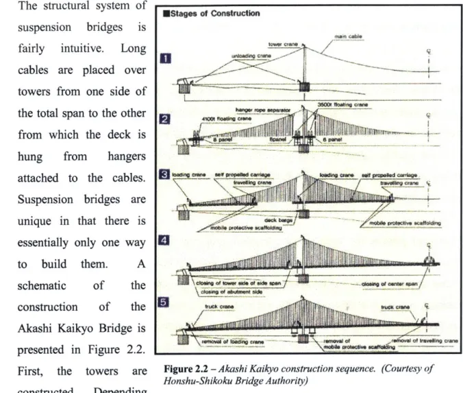
The structural system of suspension bridges is fairly intuitive. Long cables are placed over towers from one side of the total span to the other from which the deck is hung from hangers attached to the cables. Suspension bridges are unique in that there is essentially only one way to build them. A schematic of the construction of the Akashi Kaikyo Bridge is presented in Figure 2.2. First, the towers are constructed. Depending *Stag of Constructon flos*f two woPJti 040 Pofal"00ffk Mx 0E Vc~ntd~iudpgpen N
U
Figure 2.2 - Akashi Kaikyo construction sequence. (Courtesy of Honshu-Shikoku Bridge Authority)
on the size of bridge, some fairly massive and specialized equipment is needed to not only construct the foundations, but also the towers themselves. As the tower construction progresses, it acts as a cantilever which, combined with some of the large wind forces that are inherent at their construction sites, can cause dynamic forces that must be addressed.
Once the towers have been constructed, a pilot rope is placed between the towers and the anchorages. The main cables are spun using the pilot rope as a guide. Temporary platforms are constructed along the length of the cables for the laborers to work from. Once the cables are completed, the hanger ropes are placed from which the deck elements, or stiffening girder sections are placed. They are called this as it is the deck that provides stiffness to the whole system. Stiffening girders can be made of trusses, or
A.A I %V
box girders. Selection of a particular type depends on aerodynamic stability, ease of construction, maintenance, length, and so on (Okukawa, 18-8).
Box stiffening girders are made of steel and are generally selected for shorter spans and the basic dimensions are determined by fabrication, erection, maintenance, and aerodynamic stability requirements. The section erection method is the only method permissible for assembly of this type of stiffening girder (Okukawa, 18-26). This involves prefabricating box girder sections which are then floated on a barge to just below their position under the bridge. Hoisting lines are then used to lift the section into place and they are quickly secured.
"For truss girders, the design of the sectional properties is usually governed by the live load or the wind load" (Okukawa, 18-26). Here, both the section erection method and the plane section method or cantilevering method can be used. With the cantilevering method, pre-assembled panels of the stiffening girder truss are erected by extending the stiffening girders as a cantilever from the towers and anchorages. As erection progresses, each new section is cantilevered off the previously completed section. This method avoids disrupting marine traffic below unlike the section erection method above (Okukawa, 18-31). However, the cantilevering of these members requires additional strengthening of the components that make up the stiffening girder to accommodate that loading. Once the deck is completed as a continuous span, that additional strengthening required by this temporary loading is never again utilized.
Depending on the situation, as the elements of the stiffening girders are erected, whether they are by the section erection or cantilever method, the connections are either made rigidly or as hinges while the remainders of the elements are erected. Leaving the joists temporarily as hinges allows for easy analysis of behavior of the girders during construction and temporary reinforcement is usually not necessary. However, aerodynamic stability becomes an issue unless specifically addressed by additional reinforcement. With the rigid connection method, full-splice joint are immediately completed as each girder is erected into place. This keeps the stiffening girder smooth
Chapter 2: Bridge Design & Construction -25
and rigid, providing good aerodynamic stability and high construction accuracy (Okukawa, 18-30). "However, temporary reinforcement of the girders and hanger ropes to resist transient excessive stresses or controlled operation to avoid overstress are sometimes required" (Okukawa, 18-3 1). Once again, these are loading conditions that will only be experienced during the construction phase as the deck will act as a continuous span once completed. However, these conditions must be accounted for in the design or a catastrophic failure could occur.
§
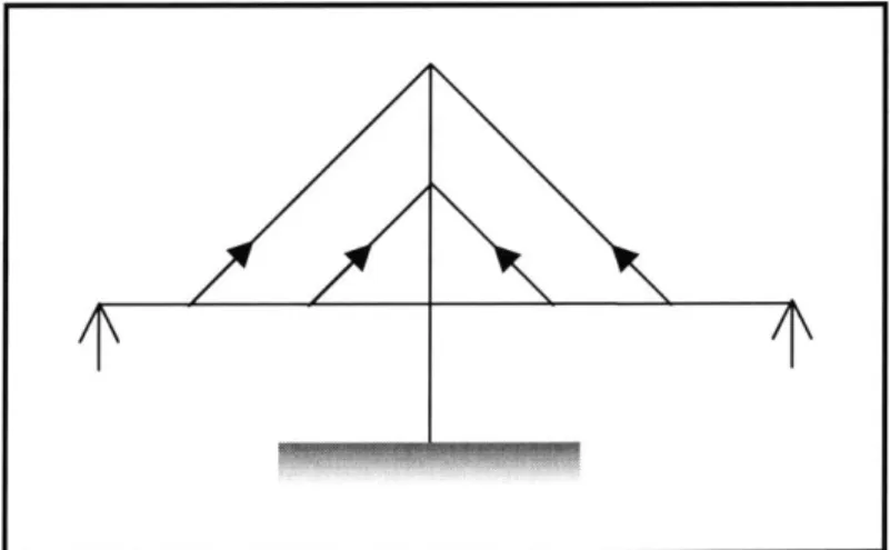
2.3 - Cable Stayed Bridges"The concept of a cable stayed bridge is simple. A bridge carries mainly vertical loads acting on the bride deck (Refer to Figure 2.3). The stay cables provide intermediate supports for the girder so that it can span a long distance. The basic structural form of a cable stayed bridge is a series of overlapping triangles comprising of the pylon, or the tower, the cables, and the girder. All these members are under predominantly axial forces, with the cables under tension and both the pylon and the girder under compression. Axially loaded members are generally more efficient than flexural members" (Tang, 19-1).
The cables are either arranged parallel to each other (harp arrangement), or the angle varies between them as they emanate from the same location on the tower (fan arrangement), or the angle will vary between each cable and the location that they meet with the tower (radial arrangement). Ideally, one wants to keep the cable spacing relatively small in order to create in effect, an elastic foundation for the deck. This helps to reduce the flexure that is experienced by the bridge deck girders.
With the majority of cable stayed bridges, there are several methods available for construction. In-stage Construction is where the segments are basically cast in place as the
formwork is advanced along the length Figure 2.4 - Schematic showing erection process of
precast concrete segments
of the bridge (this only applies to
concrete section of course). "The advantage is that the bridge does not go through high stress level changes during erection and is practically built in it final stage" (Sauvageot, 11-25). In order to achieve this, special machinery must be designed to advance the formwork and provide sufficient space and strength for laborers to place reinforcing steel.
However, this method is very time consuming and posses a safety hazard.
The next method is Push-out Construction. In this method, the segments are lined up and assembled on land and launched toward the center of the span. However this is rarely used and not well adapted for cable stayed bridges as coordination between stressing of
1. Lift Segment
SA
2. Re-stress Stay
3. Lift Seg
4. InstalL and Stress Stay
Chapter 2: Bridge Design & Construction -27
new stays and advancement of the deck is extremely difficult. During pushing, the deck is subjected to large moment variations which are not conducive to concrete (Sauvageot, 11-26). These excessive moment variations require significant strengthening of the segments solely for the construction condition. The choice of material depends on many factors and load conditions, however, in general, concrete is thought to be the best alternative due to its properties in resisting compression and its mass and damping characteristics in resisting dynamic excitation (Sauvageot, 11-22).
The most feasible and commonly used technique which is of special interest to this discussion is Cantilever Construction. Here a beam and winch assembly mounted on a previously completed portion of the deck is used to lift the precast segments into place (refer to Figure 2.4), thus the segments act as cantilevers. Once a segment is lifted, it is post tensioned to the previous segment and the lifting equipment advances along the completed span. The next segment is lifted and once again post tensioned. Once secured, the stay cables are then tensioned. These incremental stages require each segment to withstand large moments that will only be present during construction as the behavior will significantly change once all the segments are combined to act as a continuous span. The stresses in general tend to reach maximums during construction which are never again experienced during the structures life cycle (Sauvageot, 11-22).
"During construction, the stays once tensioned, also apply high concentrated forces on the section. This occurs at the middle of the cross section in the case of a single plane of stays, or at the edges with two planes of stays. These forces are not immediately available in the whole cross section, but are spread out at approximately 45 degrees. This shear lag effect is more critical during construction than in service" (Sauvageot, 11-22).
§
2.4 -Arch Bridges
Arches are one of the oldest known bridge technologies and is one of the most aesthetically pleasing. While several different variations of arches exist, the structural system remains the same. Arch bridges are characterized by their stability. In an arch, forces exerted on the structure are carried outward from the crown to the ends of the arch, where abutments exert a restraining force to keep the arch from spreading apart due to
thrust (Dupre, 13). The ideal loading for an
arch is a load uniformly distributed along its length. However due to architectural, economical, and practical considerations this is
not always possible, especially as the spans get Hinge-Less larger. Typical spans range from 100 feet to
500 feet (Matsuo). The world's longest span is
the New River Gorge Bridge in West Virginia Two-Hinged
-Hige
with a total length of 3031 feet and a centerspan length of 1700 feet.
In general, an arch is defined not only by the Three-Hinged material from which it is made (today usually
steel or precast concrete), but also its rise to span ratio which is generally within the range of
1:4.5 or 1:6 (Fox, 17-8). Tied Arch
Figure 2.5 - Arch structural types. Structurally, there are essentially four types of (Courtesy of Matsuo Bridge Co. Ltd)
arch bridges: hinge-less, two-hinged, three hinged and tied arches (Matsuo). Figure 2.5 illustrates each type.
Hinge-Less arches represent some of the very first arches built. This type of arch can only be built where the ground is very stable as there are very large forces created at the abutments as no rotation is allowed. The advantage to this type is that it is very stiff and
Chapter 2: Bridge Design & Construction -29
has minimal deflections. The Two-Hinged arches allow for rotation at the abutments and therefore is not a stiff and experiences more deflection. The most deflection is experienced with the Three-Hinged type, however it performs more favorably if there is movement in the abutments due to either settlement or earthquakes. The components of these types of arches are difficult to fabricate and for this reason combined with the large deflections, it is rarely used anymore. The final type is the Tied-Arch. This is best suited where foundation conditions are poor. Here, the horizontal component of the force at the base of the arch is taken by the girder or "tie" along the bottom as shown in Figure 2.5. In general, the Two-hinged arch made of steel is the most common as it is often the most economical (Matsuo).
Constructing an arch bridge can be tricky, since the structure is completely unstable until the two spans meet in the middle. Traditional methods of constructing arch bridges include constructing elaborate falsework. As mentioned in the introduction, these systems are sometimes more complicated than
the bridge itself. Another method Figure 2.6 - Thefirst segmentally constructed concrete that is used involves tieback anchors arch bridge in the U.S., Natchez Trace Parkway,
Franklin Tennessee. (Courtesy of US. Department of which can be used to support Transportation)
formwork for cast in place concrete or steel segments themselves. These tiebacks or cables are anchored into the ground to either side of the site and to strategic points along the segments which make up the rib of the arch being constructed. This is advantageous in that it allows construction to proceed without disrupting traffic below. If there are multiple arches, a balanced cantilever approach is used where each side is supported off a tower erected on a common pier. In some instances (typically for smaller spans), half the arch rib is constructed on two opposing abutments in the vertical position like a column. When each half is completed, they are then leaned in on each other (Fox, 17-10).
30 - Construction Based Design
One of the best examples of constructions influence on bridge design is the Eads River Bridge in St. Louis. Formally opened on July 4, 1874, it was at the time the world's first steel arch bridge, its three-arch spans--one 520 ft long and two of 502 ft--also made it the biggest bridge ever built (ENR).
Figure 2.7 - Eads Bridge Construction using the Because river traffic could not be cantilever method. (Courtesy of Columbia University)
disrupted by falsework, it was decided suspend the arch ribs from above. Temporary wooden towers were built on top of each pier and cantilevered each arch out from their sides toward the middle. Once the arches were joined at midspan, the supporting cables and towers were removed. This tieback system introduced cantilevering to American bridge construction (McGraw-Hill). It is important to note not only the design effort required for the temporary wooden towers, but also the modification to the steel ribs of the bridge to sustain the cantilever condition as the wooden towers could not bear all the weight.
§
2.5 -
Balanced Cantilever Girder Bridges
Chapter three of this thesis presents a case study using this type of construction as well as the Span-by-Span construction discussed in the following section. Therefore, detailed discussions of the specifics associated with these methods are reserved till then. Provided here is a brief overview of each type in order to familiarize the reader with the methodology of each.
"Balanced cantilever segmental construction for concrete box-girder bridges has long been recognized as one of the most efficient methods of building bridges without the need for falsework....Construction commences out from the permanent piers in both directions and proceeds in a "balanced" manner to the midspan. A final closure joint
Chapter 2: Bridge Design & Construction -31
connects cantilevers from adjacent piers. The structure itself is hence self-supporting at all stages" (Sauvageot, 11-4).
Additional loads created by this method are not limited to the nominal out of balance forces created during cantilevering. Depending on the exact method used, stressing equipment also needs to be accounted including the people operating it. The equipment itself can weigh anywhere from 5 to 10 tons and should be applied to only one side producing an unbalanced effect. Wind loads are also an important consideration especially as the cantilevers get larger (Sauvageot, 11-8). Each of these loadings induces behavior on the elements of the structure that, once complete as a continuous span, it will never experience again, which must be however included in the design.
This method is typically used in conjunction with precast concrete box girder sections. Figure 2.7 illustrate a typical cross section used. The actual
dimensions of this section vary with Figure 2.8 - Typical precast concrete box girder
the span which is typically 80 to 100 section
feet but can vary considerably depending on the design requirements. Each segment is typically 10 to 20 feet in length and weighs 40 to 80 tons (Sauvageot, 11-4). The allowable weight of these sections is typically dictated by the equipment available and the site conditions for maneuvering them into place. They are typically cast near to the construction site and are transported to the site by land or water and erected into place. Quality and continuity is maintained by using match casting. With match casting, successive segments are cast against the adjoining segment in the correct relative orientation with each other starting with the first segment from the pier. The segments are subsequently erected on the pier in the same order (Sauvageot, 11-7). This method
§
2.6
-
Span-by-Span
Constructed Bridges
"With this method, construction starts at one end of the bridge and proceeds continuously to the other end" (Sauvageot, 11-8). It is ideal for straight spans that are
relatively short (less than 160 feet Figure 2.9 -Launch Gantry at Boston's Central Artery
Tunnel Project (Courtesy of the Massachusetts Turnpike or so) but combine to create long Authority)
multiple span bridges. It is usually used where speed of construction is a major concern. The mechanism used to erect the various segments is supported on either on the bridge piers, on the edge of the previously erected span and the next pier, or at the ground level. With the precast segmental method, segments are placed and adjusted on a steel erection girder or gantry crane spanning from pier to pier, then post-tensioned together in one operation (Sauvageot, 11-12). Similar box girders are used in this method as in the previous balanced cantilever method.
This method has several advantages. First, operations can for the most part be conducted at deck level. Additionally, the reactions on the piers remain vertical as opposed to the balanced cantilever method where large overturning moments are created. Finally, they can easily accommodate various elevations along the span (Sauvageot, 11-10). Also, the design does not need to take much consideration of the construction conditions. Disadvantages include considerable upfront capital investment costs for large specialized equipment which can reach into the range of millions of dollars. Once the job is completed, there is also an issue in finding a buyer if another project is not already lined up.
As mentioned above, this method of construction will be explored in more detail with the case study presented in Chapter Three.
Chapter 2: Bridge Design & Construction -33
§
2.7 - SummaryFrom the examples provided above, we can see that during erection sequences the various components of bridges may be subjected to stresses that are quite different from those that will occur under the service loadings and which have been provided for by the designer in the traditional Design/Bid/Build method. The movement of equipment and temporary cantilevers can induce large amounts of flexure where the structural elements may only experience compression during their service life. Therefore, the constructor must engineer the bridge members through their various construction loadings, and strengthen and stabilize them as may be necessary. Additionally, temporary members may need to be provided to support and stabilize the structure as it passes through its successive erection configurations (Durkee, 45-3).
"In addition to strength problems, there are also geometric considerations. The steelwork contractor must engineer the construction sequences step by step to ensure that the structure will fit properly together as erection progresses and that the final or closing members can be moved into position and connected. Finally, the contractor must carry out the engineering studies needed to ensure that the geometry and stressing of the completed structure will be in accordance with the requirements of the design plans and specifications" (Durkee, 45-3).
The efficiencies that can be gained by using the design build method here include improved communication and coordination as well as knowledge of options and associated costs to name a few. Our focus will now be shifted to case studies to explore further the way in which construction influences the design of bridges.
Chapter 3: Central Artery Tunnel Project C19BI Contract -35
Chapter 3
-
Case Study: Segmental Bridges
The Central Artery Tunnel Project
C 19B
1
Contract
§
3.1
-
Project Overview
The C19B1 construction project is only a small portion of Boston's Central Artery Tunnel project, more commonly known as "The Big Dig." The overall project is considered by some to be the most complex and technically challenging highway project ever attempted in American history. The project is intended to dramatically reduce traffic congestion and improve mobility in one of America's oldest and most congested major cities, improve the environment, and lay the groundwork for continued economic growth for millions of New Englanders in the coming century (Amorello).
While the C19B1 contract consists of many different scopes of work, our interests are
CHARLESTOWN
CAMBRIDGE
Figure 3.1 - Aerial View of CJ9B] Project Site (Courtesy of Massachusetts Turnpike Authority)
limited to the Construction of 1-93 Mainline Viaducts (northbound and southbound) from a location north of the Charles River to the existing 1-93 Viaduct and construction of viaduct ramp structures forming an interchange connecting Route 1, and Storrow Drive with 1-93 roadways. An aerial map showing the project site is contained in Figure 3.1. In essence, the project consists of a new interchange that will connect 1-93 north of the Charles River to the Tobin Bridge, Storrow Drive, and the new underground highway.
Situated to the north and northwest of the Charles River and straddling the Millers River, the Contract area consists of the existing MBTA Rail yard and Boston Sand and Gravel sites, the existing CANA loop ramps and boat sections, and City Square. The figure above shows the project in it completed configuration. However, one of the most complex aspects of the project that is not shown is the intricate sequence of temporary ramps and traffic patterns that maintain traffic flow through out the duration of construction. This project is further complicated by the fact that it is to be constructed over Boston Sand & Gravel as well as Amtrak and the MBTA railways which must all remain in full operation. To add to the mix mentioned above, the site straddles the Millers River and there are utilities that run throughout the site for which there are few or no as built drawings.
The project was structured using the traditional Design/Bid/Build project delivery method. Several different alternatives were conceptualized and designed including steel and concrete. During the design process, it was felt that steel would be the material of choice and therefore those plans were fully developed, giving lesser attention to the concrete alternatives. However, with the ongoing construction of numerous other Central Artery Tunnel (CA/T) contracts, the availability of steel was greatly diminished unbeknownst to the designers. This greatly increased the cost associated with the alternative and subsequently made concrete the most cost effective choice for construction. In, fact of all the bids submitted, only one was for steel. This now meant that the project needed to be completed from contract documents that were not fully developed which has lead to many inefficiencies and cost overruns as we will see further in the discussion.
Chapter 3: Central Artery Tunnel Project C]9B1 Contract -37
Having been the low bidder, Modem Continental was awarded the contract in the amount of $187 million and notice to proceed was given on December 29, 1997. The north bound lanes are scheduled to be completed in November 2002 with the remainder
opening in November 2003.
The alternative that was chosen by Modem was to construct the bridge spans out of precast concrete segments that would then be post-tensioned while the columns would be cast in place (A very small portion spanning the Gilmore Bridge would be constructed of steel due to access). There are a total of 1,572 precast segments for this job. This meant that a casting plant needed to be constructed that could fabricate these segments. Given the location of the site and the inherent complexities associated with maintaining vehicular and rail traffic, a location was chosen in Maine in an abandoned airplane hanger. This location provided sufficient space to allow four segments to be cast simultaneously giving a maximum production rate of four per day. Each segment is match cast in order to insure a precise fit in the field. These segments would then be shipped to the site via trucks to await erection. A good portion of the erection took place during the night as that was the only time traffic could be interrupted.
The two main construction methods that will be the focus of this discussion are the Balanced Cantilever method and the Launch Gantry Method. As we will see, each of these methods requires careful consideration of the construction loadings as they govern the design. For this reason, these methods were incorporated into the design which dictated what methods were to be used for each portion of the project. This decision was based on the geometry of the various spans. In the areas where there is a large radius of curvature, it is not possible to use the launch gantry and therefore, the balanced cantilever method was used. A detailed discussion of each method is contained in the following sections starting with the launch gantry method.
§
3.2
-
Launch Gantry Method
A major innovation for construction of precast segmental bridges was the launching gantry. A launching gantry makes it possible to move large precast segments over the completed part of the structure and place them in series over successive piers (Precast, 1). This allows bridge spans to be constructed quickly and efficiently. An important consideration in using this method however is the large initial capital investment required. For this project, the gantry cost slightly less than two million dollars. Figure 3.2 to the right shows the gantry in
operation, preparing to lift a segment into place. Figure 3.2 -Launch Gantry in action (Courtesy of the Massachusetts Turnpike Authority)
In essence, a launching gantry is a large crane
and truss system that supports itself on bridge columns at either end of the span it is constructing. This gantry itself is rated at 750 tons and is approximately 400 feet in length. The typical span length is approximately 140 feet. With this method, the erection process becomes an integral part of the design as the segments must be able to withstand the temporary lifting loads and the columns must be able to bear the additional weight due to the gantry itself. To help illustrate this, the erection sequence is described below.
The entire process first begins with the placement of the columns or straddle beams which are cast in place (refer to Figure 3.3 for an illustration). Once they have reached sufficient strength, a pier segment is placed on top. This piece is almost solid concrete as it is required to transfer shear from the spans and the gantry which rests on it, and also act as an anchor location for the post-tensioning tendons. Transfer beams are then placed on top of the head pieces which serve as guides for the gantry. Hydraulic jacks are also used to adjust the orientation of the entire assembly to insure proper placement of the span
Chapter 3: Central Artery Tunnel Project C19BJ Contract -39
once lifted. If it happens to be the first span to be constructed, the gantry itself is lifted into place in pieces by either truck or crawler cranes. However, this only needs to be done once as the gantry has the intriguing ability to move itself from one column to another once it has completed a span. It uses a series of hydraulic jacks which can move it forward to the subsequent pier, or it can move sideways where the transfer beams act as rails. This process of moving from pier to pier takes about eight hours in total.
Once the gantry is positioned, the segments are then lifted one by one into place. Before the first segment is placed, concrete spacers are placed in order to allow a gap of approximately a foot between the pier segment and the first segment. These spacers are later removed once all the segments of span have been placed and concrete is cast in its place in order to form what is called a closure piece. Approximately the same amount of space is provided at the other end to allow the last piece to be maneuvered into place.
In order to lift the segments themselves, lifting loops consisting of high strength steel cable are cast near the four corners of the segment. The point forces created by these must be accounted for in the design. Attached to each of these lifting loops are rods. These rods are threaded on one end where they pass through a picking beam and rest on a bearing plate. A nut is then placed which allows the elevation of the segment to be adjusted by simply turning the bolt. There are four rods in total connected to two picking beams (one in the front and one in the back both parallel to the transverse axis of the segment). From here, the gantry crane then attaches itself to the picking beams and lifts the assembly into place.
As each segment is placed an epoxy compound is applied at the interface with the previous segment which acts as a glue and a sealer. In order to provide a sufficient compressive force for the compound to cure, high strength steel rods are placed along the inside web and bottom flange of the box girder segment. As each new segment is placed, these rods are extended until the entire span is completed at which time they are removed and reused on the next span.
40 - Construction Based Design
The crane of the gantry is then detached and the segment is supported by temporary rods which frame into the gantry itself. The process is repeated until all the segments have been lifted into place. The length of the various segments are adjusted during the design phase such that there is sufficient space for the closure piece. Figure 3.3 provides an illustration of each of the element in this process.
Gantry Crane
Cable Transfer Beam
Pier Segment
--Temp. Picking beam
Spacer . assembly
Pier
Segments
Figure 3.3 -Schematic of Launch Gantry System
Before the concrete for the closure piece is actually poured, the permanent post-tensioning tendons are run through the span and ten percent of their design load is applied. Once the concrete has been poured and has cured, the tendons are then tensioned to 100% of their design load and the process is essentially complete. All that remains is to insert and tension the transverse post-tensioning and remove the temporary rods which were supporting the individual segments. The gantry is then free to move to the next span.
One interesting note on this project which exemplifies the importance of attention to detail in a complex operation such as this was the improper placement of a pier segment. It was in fact placed backwards on top of the pier. This was due to an error at the fabrication site. Typically an arrow is spray painted on each pier segment as it is
Chapter 3: Central Artery Tunnel Project C19BJ Contract -41
completed to indicate it orientation which was not done properly in this case. This error was not realized until all the segments had been hung and the post-tensioning process was about to begin. With the gantry resting on it and the segments already epoxied, it was not feasible to take the segments down and remove the gantry. Therefore, false work had to be placed under the transfer beam to take the weight of the gantry and it's cargo so that the piece could be taken down and re-oriented. It turned out to be a very costly lesson learned in terms of both money and schedule.
§
3.3
-
Balanced Cantilever Method
The second, and more difficult and complicated method, is the balanced cantilever method. Both this and the Launch Gantry technique have been around for quite some time, both having been developed in Europe in the years following World War II to replace bridges damaged or destroyed. As mentioned earlier, this method has the advantage of being able to be used on tight radiuses where the launch gantry is ineffective because of the geometry.
The concept of this method is fairly simple and is as the name implies. First, as in the launch gantry method, the columns or piers are cast in place. The size of the piers for this method then to be larger due to the large P 8 effects created by the cantilevers as we will see. The next element to be erected is the pier segment. Once in place false work or temporary shoring towers are constructed on both sides of the pier. A segment is then placed on top of each false work tower between four hydraulic jacks. The jacks allow the super elevation of assembled segments to be adjusted to account for the overturning moments that are created on the radiused spans. This is illustrated in Figure 3.4 below.
Temp.
Pier Segment
E-i-
-
_
/
I
AEIWIWI
concrete block Steel rods Steel rods and Hydraulic Jacks elevation of post tensioning -False Work Overturning --moment due to curvature . Curved Segment ---... Post Tensioning
Figure 3.4 - Elevation and plan view of balanced cantilever method
Additionally, high strength steel rods are used once again to temporarily connect the segments to the previous one along with the epoxy compound. The steel rods are accessed via box outs that are formed into the surface of the deck as well as concrete tabs created on the inside of the web. These segments are now required to act as cantilevers which produces very different behavior than that of its permanent condition. At this point, permanent post-tensioning is run through the upper flange of the segments from one end of the cantilever to the other and the segments are then stressed. The configuration now acts as a rigid body and the cranes can detach from the lifting loops.
At this point, a crane lifts the next segment either to the left or to the right and it is once again epoxied and cranked down with the temporary rods. As that is completed, the next segment is lifted on the opposite side to balance the weight and secured in the same manner. Once an even number of segments are erected, they are again post-tensioned. One problem that developed here was in the removal of the temporary steel rods. Generally, these rods are used to connect two segments on either side of the pier and are extended until the span is completed at which time they are to be removed and reused.

![Figure 3.1 - Aerial View of CJ9B] Project Site (Courtesy of Massachusetts Turnpike Authority)](https://thumb-eu.123doks.com/thumbv2/123doknet/14464419.521061/35.918.159.742.701.1058/figure-aerial-view-project-courtesy-massachusetts-turnpike-authority.webp)