Selected
replacement pages have been produced for the NPC.
Please print and insert in your copy of the Code.
Issued by the Canadian Commission on Building and Fire Codes
The Change Summary table that follows describes revisions, errata and editorial updates that apply to the National Plumbing Code of Canada 2015:• Revisions are changes deemed urgent that were posted for public review from November 6, 2017 to January 2, 2018 and have been approved by the Canadian Commission on Building and Fire Codes.
• Errata are corrections to existing text.
• Editorial updates are provided for information purposes only.
Code pages containing revisions and/or errata are identified with the words “Amended Page” in the footer; pages with editorial updates and index pages with changes are not flagged. Code users should contact their local authority having jurisdiction to find out if these revisions and errata apply in their province or territory.
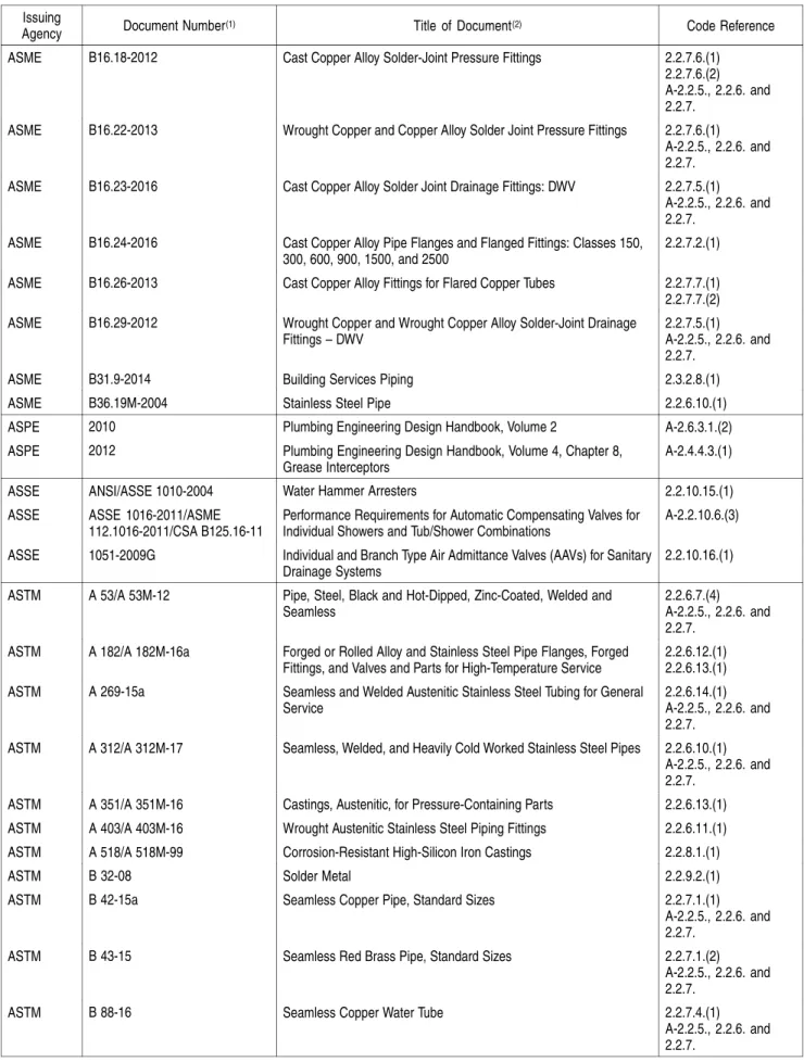
Change Summary — National Plumbing Code of Canada 2015
Division Code Reference Change (Y-M-D)Date Description of Change A Figure
A-1.4.1.2.(1)-F
erratum 2018-09-28 Figure was corrected to show the storm and sanitary building drains sloping down to street level
Figure A-1.4.1.2.(1)-G
erratum 2018-09-28 Figure was corrected to show the storm and sanitary building drains sloping down to street level
B 1.3.1.1.(1) revision 2018-09-28 Date stated in Sentence was revised to read “30 June 2017”
Table 1.3.1.2. revision 2018-09-28 Document references were updated as applicable to reflect more recent editions published as of June 30, 2017
2.2.5. revision 2018-09-28 Article 2.2.5.1. was deleted 2.2.6. revision 2018-09-28 Article 2.2.6.3. was deleted
Table 2.3.4.5. revision 2018-09-28 Entries for "Asbestos-cement pipe" and "Asbestos-cement pipe that is ≤ 300 mm long between adjacent fittings" were deleted, and Table Note (1) was deleted
2.3.5. revision 2018-09-28 Article 2.3.5.1. was revised, and Article 2.3.5.2. was deleted
2.5.6.5.(4) erratum 2018-09-28 Clauses (a) and (b) were corrected to read "… and not less than 3.5 m in any other direction ..."
2.5.7.2.(2) erratum 2018-09-28 The term "Building drains" was corrected to read "Sanitary building drains" 2.5.8.4. erratum 2018-09-28 Sentence (5) was deleted to correct the duplication of Sentence 2.5.7.2.(2)
2.6.1.11.(1) erratum 2018-09-28 Sentence was restructured, revised to clarify the intent, and corrected to read "backflow
preventers required by Sentence 2.6.2.1.(3), ..."
Table 2.8.1.1. 2018-09-28 Table was corrected as follows:
Article 2.2.2.4.: entry was corrected to read "2.2.2.3." Article 2.2.2.5.: entry was corrected to read "2.2.2.4." errata
(unless otherwise indicated)
Article 2.2.2.6.: entry was corrected to read "2.2.2.5."
Change Summary — National Plumbing Code of Canada 2015 (Continued)
Division Code Reference Change Date
(Y-M-D) Description of Change B
(continued)
Table 2.8.1.1. (continued)
2018-09-28 Sentence 2.2.3.2.(3): "[F81-OP5]" was added revision Article 2.2.5.1.: entry was deleted
Sentence 2.2.5.9.(1): "[F20,F80,F81-OH2.1,OH2.3]" was corrected to read "[F20,F80,F81-OH2.1]", and "[F20,F80-OP5]" was corrected to read "[F20,F80,F81-OP5]"
Sentence 2.2.6.2.(1): "[F40,F81-OH1.1]" was corrected to read "[F81-OH1.1]", "[F20,F30-OS2.1]" was deleted, and "[F20,F30-OS3.1]" was corrected to read "[F20-OS3.1]"
revision Article 2.2.6.3.: entry was deleted
Articles 2.2.6.11. to 2.2.6.13., Sentences (1) and (2): "[F71,F80-OH2.1,OH2.3]" was corrected to read "[F80-OH2.1]", "[F46-OH2.2]" was corrected to read "[F46,F80-OH2.2]", and the term "water systems" was italicized
Sentences 2.2.6.14.(1) and (2): "[F80-OH2.1] Applies to drainage systems and venting
systems. [F46,F80-OH2.2] Applies to water systems." was added
Sentences 2.2.6.15.(1) and (2): "[F80-OP5]" was added
Sentence 2.2.10.17.(1): "[F46,F70-OH2.2]" was corrected to read "[F46-OH2.2]" revision Article 2.3.5.1.: entry was revised to read "Protection of Piping"
revision Sentence 2.3.5.1.(1): "[F81-OP5]" was revised to read "(a) [F81-OP5]" revision Article 2.3.5.2.: entry was deleted
Article 2.3.5.4.: entry was corrected to read "Protection Against Freezing" Sentence 2.3.6.2.(1): "[F81-OP5]" was added
Sentence 2.3.6.2.(2): "[F81-OH2.1,OH2.3]" was corrected to read "[F81-OH2.1]" Sentence 2.4.3.6.(1): "[F62-OP5]" was corrected to read "(a) [F62-OP5]", and "(b) [F81-OH2.1]" was added
Sentence 2.4.5.3.(1): "[F81-OH1.1]" was added
Sentence 2.5.2.1.(1): "[F40,F81-OH1.1]" was corrected to read "[F81-OH1.1]" Sentence 2.5.6.2.(1): "[F81-OS1.1]" was corrected to read "[F81-OH1.1]" Sentence 2.5.7.5.(1): "[F81-OH2.1]" was corrected to read "[F81-OH1.1]" Sentence 2.5.8.1.(2): entry was deleted
Sentence 2.5.8.4.(5): entry was deleted Table A-2.2.5,
2.2.6. and 2.2.7.
revision 2018-09-28 Entries for "Asbestos-cement DWV pipe" were deleted Figure A-2.3.3.9. revision 2018-09-28 Legend was revised to read "12. mild steel and cast iron"
Note A-2.3.5.1.(1)
revision 2018-09-28 Note was renumbered "A-2.3.5.1.(1)(a)" and label for arrow indicating backfill in Figure was revised to read "Backfill complying with Clause 2.3.5.1.(1)(a)"
A-2.3.5.2.(1) revision 2018-09-28 Note was deleted Figure
A-2.4.9.3.(3)
erratum 2018-09-28 Depiction of the measurement of the standpipes was corrected Table
A-2.6.2.4.(2)
erratum 2018-09-28 Subtitle was corrected to read "Forming Part of Note A-2.6.2.4.(2)"
A-2.6.3.1.(2) errata 2018-09-28 Text in the second paragraph was corrected to read "... (Small Building Method) …", and division title was corrected to read "Small Building Method"
Table A-2.6.3.1.(2)-A
erratum 2018-09-28 Title was corrected to read "… Using the Small Building Method(1)"
Figure A-2.6.3.1.(2)-A
erratum 2018-09-28 Label "HWT" under the service water heater was corrected to read "SWH", and text at the bottom of the Figure was corrected to read "For use with Small Building and …"
Change Summary — National Plumbing Code of Canada 2015 (Continued)
Division Code Reference Change Date
(Y-M-D) Description of Change B
(continued)
Figure A-2.6.3.4.(5)-B
erratum 2018-09-28 Label "SWH" was corrected to read "SHWR", load on Pipe A was corrected to read "2.8 FU", and label "HWT" under the service water heater was corrected to read "SWH" Letter A revision 2018-09-28 Asbestos-cement pipe and fittings: entry was deleted
Letter D revision 2018-09-28 Drainage piping: "asbestos-cement, 2.2.5.1." was deleted Letter F revision 2018-09-28 Fittings: "asbestos-cement, 2.2.5.1." was deleted Index
Letter P revision 2018-09-28 Pipe: "asbestos-cement, 2.2.5.1., 2.2.6.3., 2.3.4.5., 2.3.5.2." was deleted n/a Symbols and
Abbreviations
editorial update
2018-09-28 Entry for "HWT" was deleted, and entry for "SHWR" was added
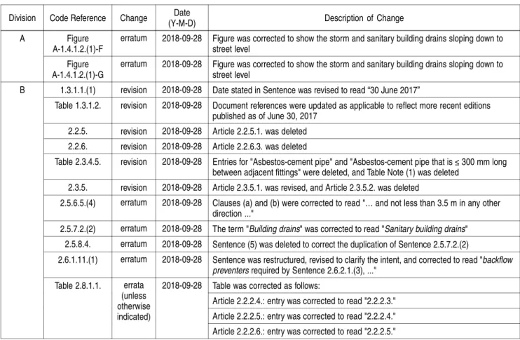
vent stack
This end of the branch
vent could be connected
to a stack vent or vent
header or lead directly to outside air.
branch vent – joins
junction of circuit
vent and individual
and continuous
vent to the vent stack
circuit vent individual and continuous vent LA V WCs EG01120B Figure A-1.4.1.2.(1)-D Branch Vent
Note to Figure A-1.4.1.2.(1)-D:
(1) See also the definitions of header and drainage system in Article 1.4.1.2.
EG01121B
Figure A-1.4.1.2.(1)-E Continuous Vent
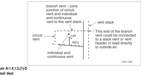
street level
Figure A-1.4.1.2.(1)-F Drainage System
street level
Figure A-1.4.1.2.(1)-G Venting System
EG01124C
Figure A-1.4.1.2.(1)-H
Fixture Outlet Pipe and Trap Arm
vent header
upper end of vent header terminates in outside air
vent stacks or stack vents
vent header
upper end of vent header terminates in outside air
vent stacks or stack vents stack vent EG01125A Figure A-1.4.1.2.(1)-I Vent Header
Note to Figure A-1.4.1.2.(1)-I:
(1) Although a vent header is similar to a branch vent, it serves the special purpose of connecting the tops of stack vents or vent stacks. To make certain that it is adequate for that purpose, it is made larger than a branch vent. The developed length used to determine its size is the total length from the most distant soil-or-waste pipe to outside air, rather than the shorter length used to size a branch vent.
Part 1
General
Section 1.1. General
1.1.1.
Application
1.1.1.1. Application
1) This Part applies to all plumbing systems covered in this Code. (See Article 1.1.1.1. of Division A.)
1.1.2.
Objectives and Functional Statements
1.1.2.1. Attribution to Acceptable Solutions
1) For the purposes of compliance with this Code as required in
Clause 1.2.1.1.(1)(b) of Division A, the objectives and functional statements attributed to the acceptable solutions in Division B shall be the objectives and functional statements identified in Section 2.8. (See Note A-1.1.2.1.(1).)
Section 1.2. Terms and Abbreviations
1.2.1.
Definitions of Words and Phrases
1.2.1.1. Non-defined Terms
1) Words and phrases used in Division B that are not included in the list of definitions in Article 1.4.1.2. of Division A shall have the meanings that are commonly assigned to them in the context in which they are used, taking into account the specialized use of terms by the various trades and professions to which the terminology applies.
2) Where objectives and functional statements are referred to in Division B, they shall be the objectives and functional statements described in Parts 2 and 3 of Division A.
3) Where acceptable solutions are referred to in Division B, they shall be the provisions stated in Part 2.
1.2.1.2. Defined Terms
1) The words and terms in italics in Division B shall have the meanings assigned to them in Article 1.4.1.2. of Division A.
1.2.2.
Symbols and Other Abbreviations
1.2.2.1. Symbols and Other Abbreviations
1) The symbols and other abbreviations in Division B shall have the meanings assigned to them in Article 1.4.2.1. of Division A and Article 1.3.2.1.
Section 1.3.
Referenced Documents and
Organizations
1.3.1.
Referenced Documents
1.3.1.1. Effective Date
1) Unless otherwise specified herein, the documents referenced in this Code shall include all amendments, revisions, reaffirmations, reapprovals, addenda and supplements effective to 30 June 2017.
1.3.1.2. Applicable Editions
1) Where documents are referenced in this Code, they shall be the editions designated in Table 1.3.1.2.
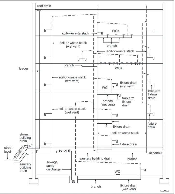
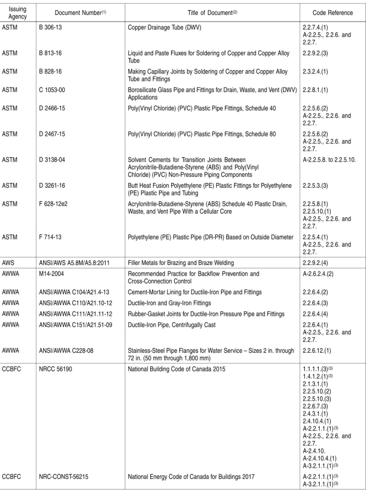
Table 1.3.1.2.
Documents Referenced in the National Plumbing Code of Canada 2015 Forming Part of Sentence 1.3.1.2.(1)
Issuing
Agency Document Number(1) Title of Document(2) Code Reference ANSI/CSA ANSI Z21.22-2015/CSA 4.4-2015 Relief Valves for Hot Water Supply Systems 2.2.10.11.(1) ASHRAE 2013 ASHRAE Handbook – Fundamentals A-2.6.3.1.(2) ASHRAE 2011 ASHRAE Handbook – HVAC Applications A-2.6.3.1.(2) ASME/CSA ASME A112.3.4-2013/CSA
B45.9-13
Plumbing Fixtures with Pumped Waste and Macerating Toilet Systems 2.2.2.2.(1) ASME/CSA ASME A112.18.1-2012/CSA
B125.1-12
Plumbing Supply Fittings 2.2.10.6.(1) 2.2.10.7.(1) ASME/CSA ASME A112.18.2-2015/CSA
B125.2-15
Plumbing Waste Fittings 2.2.3.3.(1) 2.2.10.6.(6) ASME/CSA ASME A112.19.1-2013/CSA
B45.2-13
Enamelled Cast Iron and Enamelled Steel Plumbing Fixtures 2.2.2.2.(1) ASME/CSA ASME A112.19.2-2013/CSA
B45.1-13
Ceramic Plumbing Fixtures 2.2.2.2.(1) ASME/CSA ASME A112.19.3-2017/CSA
B45.4-17
Stainless Steel Plumbing Fixtures 2.2.2.2.(1) ASME/CSA ASME A112.19.7-2012/CSA
B45.10-12
Hydromassage Bathtub Systems 2.2.2.2.(1) ASME B16.3-2016 Malleable Iron Threaded Fittings: Classes 150 and 300 2.2.6.6.(1)
A-2.2.5., 2.2.6. and 2.2.7.
ASME B16.4-2011 Gray Iron Threaded Fittings: Classes 125 and 250 2.2.6.5.(1) A-2.2.5., 2.2.6. and 2.2.7.
ASME B16.5-2017 Pipe Flanges and Flanged Fittings: NPS ½ Through NPS 24 Metric/Inch Standard
2.2.6.12.(1) ASME B16.9-2012 Factory Made Wrought Buttwelding Fittings 2.2.6.11.(1) 2.2.6.14.(1) ASME B16.12-2009 Cast Iron Threaded Drainage Fittings 2.2.6.3.(1) ASME B16.15-2013 Cast Copper Alloy Threaded Fittings: Classes 125 and 250 2.2.7.3.(1)
A-2.2.5., 2.2.6. and 2.2.7.
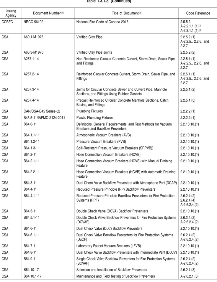
Table 1.3.1.2. (Continued)
Issuing
Agency Document Number(1) Title of Document(2) Code Reference ASME B16.18-2012 Cast Copper Alloy Solder-Joint Pressure Fittings 2.2.7.6.(1)
2.2.7.6.(2) A-2.2.5., 2.2.6. and 2.2.7.
ASME B16.22-2013 Wrought Copper and Copper Alloy Solder Joint Pressure Fittings 2.2.7.6.(1) A-2.2.5., 2.2.6. and 2.2.7.
ASME B16.23-2016 Cast Copper Alloy Solder Joint Drainage Fittings: DWV 2.2.7.5.(1) A-2.2.5., 2.2.6. and 2.2.7.
ASME B16.24-2016 Cast Copper Alloy Pipe Flanges and Flanged Fittings: Classes 150, 300, 600, 900, 1500, and 2500
2.2.7.2.(1) ASME B16.26-2013 Cast Copper Alloy Fittings for Flared Copper Tubes 2.2.7.7.(1) 2.2.7.7.(2) ASME B16.29-2012 Wrought Copper and Wrought Copper Alloy Solder-Joint Drainage
Fittings – DWV
2.2.7.5.(1) A-2.2.5., 2.2.6. and 2.2.7.
ASME B31.9-2014 Building Services Piping 2.3.2.8.(1) ASME B36.19M-2004 Stainless Steel Pipe 2.2.6.10.(1) ASPE 2010 Plumbing Engineering Design Handbook, Volume 2 A-2.6.3.1.(2) ASPE 2012 Plumbing Engineering Design Handbook, Volume 4, Chapter 8,
Grease Interceptors
A-2.4.4.3.(1) ASSE ANSI/ASSE 1010-2004 Water Hammer Arresters 2.2.10.15.(1) ASSE ASSE 1016-2011/ASME
112.1016-2011/CSA B125.16-11
Performance Requirements for Automatic Compensating Valves for Individual Showers and Tub/Shower Combinations
A-2.2.10.6.(3) ASSE 1051-2009G Individual and Branch Type Air Admittance Valves (AAVs) for Sanitary
Drainage Systems
2.2.10.16.(1) ASTM A 53/A 53M-12 Pipe, Steel, Black and Hot-Dipped, Zinc-Coated, Welded and
Seamless
2.2.6.7.(4) A-2.2.5., 2.2.6. and 2.2.7.
ASTM A 182/A 182M-16a Forged or Rolled Alloy and Stainless Steel Pipe Flanges, Forged Fittings, and Valves and Parts for High-Temperature Service
2.2.6.12.(1) 2.2.6.13.(1) ASTM A 269-15a Seamless and Welded Austenitic Stainless Steel Tubing for General
Service
2.2.6.14.(1) A-2.2.5., 2.2.6. and 2.2.7.
ASTM A 312/A 312M-17 Seamless, Welded, and Heavily Cold Worked Stainless Steel Pipes 2.2.6.10.(1) A-2.2.5., 2.2.6. and 2.2.7.
ASTM A 351/A 351M-16 Castings, Austenitic, for Pressure-Containing Parts 2.2.6.13.(1) ASTM A 403/A 403M-16 Wrought Austenitic Stainless Steel Piping Fittings 2.2.6.11.(1) ASTM A 518/A 518M-99 Corrosion-Resistant High-Silicon Iron Castings 2.2.8.1.(1)
ASTM B 32-08 Solder Metal 2.2.9.2.(1)
ASTM B 42-15a Seamless Copper Pipe, Standard Sizes 2.2.7.1.(1) A-2.2.5., 2.2.6. and 2.2.7.
ASTM B 43-15 Seamless Red Brass Pipe, Standard Sizes 2.2.7.1.(2) A-2.2.5., 2.2.6. and 2.2.7.
ASTM B 88-16 Seamless Copper Water Tube 2.2.7.4.(1) A-2.2.5., 2.2.6. and 2.2.7.
Table 1.3.1.2. (Continued)
Issuing
Agency Document Number(1) Title of Document(2) Code Reference ASTM B 306-13 Copper Drainage Tube (DWV) 2.2.7.4.(1)
A-2.2.5., 2.2.6. and 2.2.7.
ASTM B 813-16 Liquid and Paste Fluxes for Soldering of Copper and Copper Alloy Tube
2.2.9.2.(3) ASTM B 828-16 Making Capillary Joints by Soldering of Copper and Copper Alloy
Tube and Fittings
2.3.2.4.(1) ASTM C 1053-00 Borosilicate Glass Pipe and Fittings for Drain, Waste, and Vent (DWV)
Applications
2.2.8.1.(1) ASTM D 2466-15 Poly(Vinyl Chloride) (PVC) Plastic Pipe Fittings, Schedule 40 2.2.5.6.(2)
A-2.2.5., 2.2.6. and 2.2.7.
ASTM D 2467-15 Poly(Vinyl Chloride) (PVC) Plastic Pipe Fittings, Schedule 80 2.2.5.6.(2) A-2.2.5., 2.2.6. and 2.2.7.
ASTM D 3138-04 Solvent Cements for Transition Joints Between Acrylonitrile-Butadiene-Styrene (ABS) and Poly(Vinyl Chloride) (PVC) Non-Pressure Piping Components
A-2.2.5.8. to 2.2.5.10.
ASTM D 3261-16 Butt Heat Fusion Polyethylene (PE) Plastic Fittings for Polyethylene (PE) Plastic Pipe and Tubing
2.2.5.3.(3) ASTM F 628-12e2 Acrylonitrile-Butadiene-Styrene (ABS) Schedule 40 Plastic Drain,
Waste, and Vent Pipe With a Cellular Core
2.2.5.8.(1) 2.2.5.10.(1) A-2.2.5., 2.2.6. and 2.2.7.
ASTM F 714-13 Polyethylene (PE) Plastic Pipe (DR-PR) Based on Outside Diameter 2.2.5.4.(1) A-2.2.5., 2.2.6. and 2.2.7.
AWS ANSI/AWS A5.8M/A5.8:2011 Filler Metals for Brazing and Braze Welding 2.2.9.2.(4) AWWA M14-2004 Recommended Practice for Backflow Prevention and
Cross-Connection Control
A-2.6.2.4.(2) AWWA ANSI/AWWA C104/A21.4-13 Cement-Mortar Lining for Ductile-Iron Pipe and Fittings 2.2.6.4.(2) AWWA ANSI/AWWA C110/A21.10-12 Ductile-Iron and Gray-Iron Fittings 2.2.6.4.(3) AWWA ANSI/AWWA C111/A21.11-12 Rubber-Gasket Joints for Ductile-Iron Pressure Pipe and Fittings 2.2.6.4.(4) AWWA ANSI/AWWA C151/A21.51-09 Ductile-Iron Pipe, Centrifugally Cast 2.2.6.4.(1)
A-2.2.5., 2.2.6. and 2.2.7.
AWWA ANSI/AWWA C228-08 Stainless-Steel Pipe Flanges for Water Service – Sizes 2 in. through 72 in. (50 mm through 1,800 mm)
2.2.6.12.(1) CCBFC NRCC 56190 National Building Code of Canada 2015 1.1.1.1.(3)(3)
1.4.1.2.(1)(3) 2.1.3.1.(1) 2.2.5.10.(2) 2.2.5.10.(3) 2.2.6.7.(3) 2.4.3.1.(1) 2.4.10.4.(1) A-2.2.1.1.(1)(3) A-2.2.5., 2.2.6. and 2.2.7. A-2.4.10. A-2.4.10.4.(1) A-3.2.1.1.(1)(3)
CCBFC NRC-CONST-56215 National Energy Code of Canada for Buildings 2017 A-2.2.1.1.(1)(3)
A-3.2.1.1.(1)(3)
Table 1.3.1.2. (Continued)
Issuing
Agency Document Number(1) Title of Document(2) Code Reference CCBFC NRCC 56192 National Fire Code of Canada 2015 2.5.5.2.
A-2.2.1.1.(1)(3)
A-3.2.1.1.(1)(3)
CSA A60.1-M1976 Vitrified Clay Pipe 2.2.5.2.(1) A-2.2.5., 2.2.6. and 2.2.7.
CSA A60.3-M1976 Vitrified Clay Pipe Joints 2.2.5.2.(2) CSA A257.1-14 Non-Reinforced Circular Concrete Culvert, Storm Drain, Sewer Pipe,
and Fittings
2.2.5.1.(1) A-2.2.5., 2.2.6. and 2.2.7.
CSA A257.2-14 Reinforced Circular Concrete Culvert, Storm Drain, Sewer Pipe, and Fittings
2.2.5.1.(1) A-2.2.5., 2.2.6. and 2.2.7.
CSA A257.3-14 Joints for Circular Concrete Sewer and Culvert Pipe, Manhole Sections, and Fittings Using Rubber Gaskets
2.2.5.1.(2) CSA A257.4-14 Precast Reinforced Circular Concrete Manhole Sections, Catch
Basins, and Fittings
2.2.5.1.(5) CSA CAN/CSA-B45 Series-02 Plumbing Fixtures 2.2.2.2.(1) CSA B45.5-11/IAPMO Z124-2011 Plastic Plumbing Fixtures 2.2.2.2.(1) CSA B64.0-11 Definitions, General Requirements, and Test Methods for Vacuum
Breakers and Backflow Preventers
2.2.10.10.(1) CSA B64.1.1-11 Atmospheric Vacuum Breakers (AVB) 2.2.10.10.(1) CSA B64.1.2-11 Pressure Vacuum Breakers (PVB) 2.2.10.10.(1) CSA B64.1.3-11 Spill-Resistant Pressure Vacuum Breakers (SRPVB)) 2.2.10.10.(1) CSA B64.2-11 Hose Connection Vacuum Breakers (HCVB) 2.2.10.10.(1) CSA B64.2.1-11 Hose Connection Vacuum Breakers (HCVB) with Manual Draining
Feature
2.2.10.10.(1) CSA B64.2.2-11 Hose Connection Vacuum Breakers (HCVB) with Automatic Draining
Feature
2.2.10.10.(1) CSA B64.3-11 Dual Check Valve Backflow Preventers with Atmospheric Port (DCAP) 2.2.10.10.(1) CSA B64.4-11 Reduced Pressure Principle (RP) Backflow Preventers 2.2.10.10.(1) CSA B64.4.1-11 Reduced Pressure Principle Backflow Preventers for Fire Protection
Systems (RPF)
2.6.2.4.(2) 2.6.2.4.(4) A-2.6.2.4.(2) CSA B64.5-11 Double Check Valve (DCVA) Backflow Preventers 2.2.10.10.(1) CSA B64.5.1-11 Double Check Valve Backflow Preventers for Fire Protection Systems
(DCVAF)
2.6.2.4.(2) A-2.6.2.4.(2) CSA B64.6-11 Dual Check Valve (DuC) Backflow Preventers 2.2.10.10.(1) CSA B64.6.1-11 Dual Check Valve Backflow Preventers for Fire Protection Systems
(DuCF)
2.6.2.4.(2) A-2.6.2.4.(2) CSA B64.7-11 Laboratory Faucet Vacuum Breakers (LFVB) 2.2.10.10.(1) CSA B64.8-11 Dual Check Valve Backflow Preventers with Intermediate Vent (DuCV) 2.2.10.10.(1) CSA B64.9-11 Single Check Valve Backflow Preventers for Fire Protection Systems
(SCVAF)
2.6.2.4.(2) A-2.6.2.4.(2) CSA B64.10-17 Selection and Installation of Backflow Preventers 2.6.2.1.(3) CSA B64.10.1-17 Maintenance and Field Testing of Backflow Preventers A-2.6.2.1.(3)
Table 1.3.1.2. (Continued)
Issuing
Agency Document Number(1) Title of Document(2) Code Reference CSA B70-12 Cast Iron Soil Pipe, Fittings, and Means of Joining 2.2.6.1.(1)
2.4.6.4.(2) A-2.2.5., 2.2.6. and 2.2.7.
CSA B70.1-03 Frames and Covers for Maintenance Holes and Catchbasins 2.2.6.2.(1) CSA B125.3-12 Plumbing Fittings 2.2.10.6.(1)
2.2.10.7.(2) 2.2.10.10.(2) A-2.6.1.11.(1) CSA CAN/CSA-B128.1-06 Design and Installation of Non-Potable Water Systems 2.7.4.1.(1) CSA B137.1-17 Polyethylene (PE) Pipe, Tubing, and Fittings for Cold-Water Pressure
Services
2.2.5.3.(1) A-2.2.5., 2.2.6. and 2.2.7.
CSA B137.2-17 Polyvinylchloride (PVC) Injection-Moulded Gasketed Fittings for Pressure Applications
2.2.5.6.(3) A-2.2.5., 2.2.6. and 2.2.7.
CSA B137.3-17 Rigid Polyvinylchloride (PVC) Pipe and Fittings for Pressure Applications
2.2.5.6.(1) A-2.2.5., 2.2.6. and 2.2.7.
CSA B137.5-17 Crosslinked Polyethylene (PEX) Tubing Systems for Pressure Applications
2.2.5.5.(1) A-2.2.5., 2.2.6. and 2.2.7.
A-2.2.5.5.(1) CSA B137.6-17 Chlorinated Polyvinylchloride (CPVC) Pipe, Tubing, and Fittings for
Hot- and Cold-Water Distribution Systems
2.2.5.7.(1) A-2.2.5., 2.2.6. and 2.2.7.
A-2.2.5.8. to 2.2.5.10. CSA B137.9-17 Polyethylene/Aluminum/Polyethylene (PE-AL-PE) Composite
Pressure-Pipe Systems
2.2.5.11.(1) A-2.2.5., 2.2.6. and 2.2.7.
A-2.2.5.11.(1) CSA B137.10-17 Crosslinked Polyethylene/Aluminum/Crosslinked Polyethylene
(PEX-AL-PEX) Composite Pressure-Pipe Systems
2.2.5.11.(4) 2.2.5.12.(1) A-2.2.5., 2.2.6. and 2.2.7.
A-2.2.5.12.(1) CSA B137.11-17 Polypropylene (PP-R) Pipe and Fittings for Pressure Applications 2.2.5.13.(1)
A-2.2.5., 2.2.6. and 2.2.7.
A-2.2.5.13.(1) CSA B158.1-1976 Cast Brass Solder Joint Drainage, Waste and Vent Fittings 2.2.10.1.(1) CSA CAN/CSA-B181.1-15 Acrylonitrile-Butadiene-Styrene (ABS) Drain, Waste, and Vent Pipe
and Pipe Fittings
2.2.5.8.(1) 2.2.5.9.(1) 2.2.5.10.(1) 2.4.6.4.(2) A-2.2.5., 2.2.6. and 2.2.7. A-2.2.5.8. to 2.2.5.10. CSA CAN/CSA-B181.2-15 Polyvinylchloride (PVC) and Chlorinated Polyvinylchloride (CPVC)
Drain, Waste, and Vent Pipe and Pipe Fittings
2.2.5.8.(1) 2.2.5.9.(1) 2.2.5.10.(1) 2.4.6.4.(2) A-2.2.5., 2.2.6. and 2.2.7. A-2.2.5.8. to 2.2.5.10.
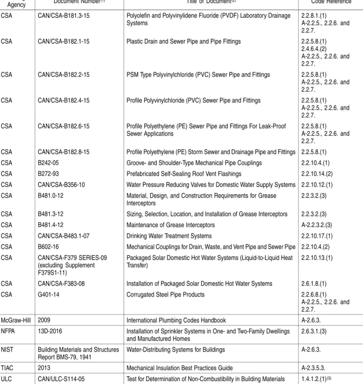
Table 1.3.1.2. (Continued)
Issuing
Agency Document Number(1) Title of Document(2) Code Reference CSA CAN/CSA-B181.3-15 Polyolefin and Polyvinylidene Fluoride (PVDF) Laboratory Drainage
Systems
2.2.8.1.(1) A-2.2.5., 2.2.6. and 2.2.7.
CSA CAN/CSA-B182.1-15 Plastic Drain and Sewer Pipe and Pipe Fittings 2.2.5.8.(1) 2.4.6.4.(2) A-2.2.5., 2.2.6. and 2.2.7.
CSA CAN/CSA-B182.2-15 PSM Type Polyvinylchloride (PVC) Sewer Pipe and Fittings 2.2.5.8.(1) A-2.2.5., 2.2.6. and 2.2.7.
CSA CAN/CSA-B182.4-15 Profile Polyvinylchloride (PVC) Sewer Pipe and Fittings 2.2.5.8.(1) A-2.2.5., 2.2.6. and 2.2.7.
CSA CAN/CSA-B182.6-15 Profile Polyethylene (PE) Sewer Pipe and Fittings For Leak-Proof Sewer Applications
2.2.5.8.(1) A-2.2.5., 2.2.6. and 2.2.7.
CSA CAN/CSA-B182.8-15 Profile Polyethylene (PE) Storm Sewer and Drainage Pipe and Fittings 2.2.5.8.(1) CSA B242-05 Groove- and Shoulder-Type Mechanical Pipe Couplings 2.2.10.4.(1) CSA B272-93 Prefabricated Self-Sealing Roof Vent Flashings 2.2.10.14.(2) CSA CAN/CSA-B356-10 Water Pressure Reducing Valves for Domestic Water Supply Systems 2.2.10.12.(1) CSA B481.0-12 Material, Design, and Construction Requirements for Grease
Interceptors
2.2.3.2.(3) CSA B481.3-12 Sizing, Selection, Location, and Installation of Grease Interceptors 2.2.3.2.(3) CSA B481.4-12 Maintenance of Grease Interceptors A-2.2.3.2.(3) CSA CAN/CSA-B483.1-07 Drinking Water Treatment Systems 2.2.10.17.(1) CSA B602-16 Mechanical Couplings for Drain, Waste, and Vent Pipe and Sewer Pipe 2.2.10.4.(2) CSA CAN/CSA-F379 SERIES-09
(excluding Supplement F379S1-11)
Packaged Solar Domestic Hot Water Systems (Liquid-to-Liquid Heat Transfer)
2.2.10.13.(1)
CSA CAN/CSA-F383-08 Installation of Packaged Solar Domestic Hot Water Systems 2.6.1.8.(1) CSA G401-14 Corrugated Steel Pipe Products 2.2.6.8.(1)
A-2.2.5., 2.2.6. and 2.2.7.
McGraw-Hill 2009 International Plumbing Codes Handbook A-2.6.3. NFPA 13D-2016 Installation of Sprinkler Systems in One- and Two-Family Dwellings
and Manufactured Homes
2.6.3.1.(3) NIST Building Materials and Structures
Report BMS-79, 1941
Water-Distributing Systems for Buildings A-2.6.3. TIAC 2013 Mechanical Insulation Best Practices Guide A-2.3.5.3. ULC CAN/ULC-S114-05 Test for Determination of Non-Combustibility in Building Materials 1.4.1.2.(1)(3)
Notes to Table 1.3.1.2.:
(1) Some documents may have been reaffirmed or reapproved. Check with the applicable issuing agency for up-to-date information. (2) Some titles have been abridged to omit superfluous wording.
(3) Code reference is in Division A.
1.3.2.
Organizations
1.3.2.1. Abbreviations of Proper Names
1) The abbreviations of proper names in this Code shall have the meanings assigned to them in this Article.
ANSI ... American National Standards Institute (www.ansi.org)
ASHRAE ... American Society of Heating, Refrigerating and Air-Conditioning Engineers (www.ashrae.org)
ASME ... American Society of Mechanical Engineers (www.asme.org) ASPE ... American Society of Plumbing Engineers (www.aspe.org)
ASSE ... American Society of Sanitary Engineering (www.asse-plumbing.org) ASTM ... American Society for Testing and Materials International
(www.astm.org)
AWS ... American Welding Society (www.aws.org)
AWWA ... American Water Works Association (www.awwa.org) CAN ... National Standard of Canada designation
CCBFC ... Canadian Commission on Building and Fire Codes (see NRC) CGSB ... Canadian General Standards Board
(www.tpsgc-pwgsc.gc.ca/ongc-cgsb/index-eng.html) CSA ... CSA Group (www.csagroup.org)
NBC ... National Building Code of Canada 2015 NFC ... National Fire Code of Canada 2015
NFPA ... National Fire Protection Association (www.nfpa.org)
NIST ... National Institute of Standards and Technology (www.nist.gov) NPC ... National Plumbing Code of Canada 2015
NRC ... National Research Council of Canada (Ottawa, Ontario K1A 0R6; www.nrc-cnrc.gc.ca)
NRC-IRC ... National Research Council of Canada, Institute for Research in Construction (former name of the NRC Construction Research Centre) ULC ... ULC Standards (canada.ul.com/ulcstandards)
g) hydromassage bathtubs shall conform to ASME A112.19.7/CSA B45.10, “Hydromassage Bathtub Systems,”and
h) macerating toilet systems shall conform to ASME A112.3.4/CSA B45.9, “Plumbing Fixtures with Pumped Waste and Macerating Toilet Systems.”
2.2.2.3. Showers
1) Shower receptors shall be constructed and arranged so that water cannot leak through the walls or floor.
2) Not more than 6 shower heads shall be served by a single shower drain. 3) Where 2 or more shower heads are served by a shower drain, the floor shall be sloped and the drain located so that water from one head cannot flow over the area that serves another head. (See Note A-2.2.2.3.(3).)
4) Except for column showers, when a battery of shower heads is installed, the horizontal distance between 2 adjacent shower heads shall be not less than 750 mm.
2.2.2.4. Concealed Overflows
1) A dishwashing sink and a food preparation sink shall not have concealed overflows. (See Note A-2.2.2.4.(1).)
2.2.2.5. Water Closets in Public Washrooms
1) When a water closet is installed in a washroom for public use, it shall be of the elongated type and provided with a seat of the open front type.
2.2.3.
Traps and Interceptors
2.2.3.1. Traps
1) Except as provided for in Sentence (2), traps shall a) have a trap seal depth of not less than 38 mm,
b) be so designed that failure of the seal walls will cause exterior leakage, and c) have a water seal that does not depend on the action of moving parts. (See Note A-2.2.3.1.(1) and (3).)
2) The trap seal depth on fixtures draining to an acid waste system shall be a minimum of 50 mm.
3) Except for a floor-mounted service sink, every trap that serves a lavatory, a sink or a laundry tray shall
a) be provided with a cleanout plug located at the lowest point of the trap and of the same material as the trap, except that a cast-iron trap shall be provided with a brass cleanout plug, or
b) be designed so that part of the trap can be removed for cleaning purposes. (See Note A-2.2.3.1.(1) and (3).)
4) A bell trap shall not be installed in a drainage system. (See Note A-2.2.3.1.(4).) 5) A drum trap shall not be used as a fixture trap unless required to serve as an
interceptor and access for servicing is provided.
2.2.3.2. Interceptors
1) Interceptors shall be designed so that they can be readily cleaned.
2) Grease interceptors shall
a) be designed so that they do not become air bound, and b) not have a water jacket.
3) Grease interceptors shall be selected and installed in conformance with a) CSA B481.0, “Material, Design, and Construction Requirements for Grease
Interceptors,” and
b) CSA B481.3, “Sizing, Selection, Location, and Installation of Grease Interceptors.”
(See Note A-2.2.3.2.(3).)
2.2.3.3. Tubular Traps
1) Tubular metal or plastic traps conforming to ASME A112.18.2/CSA B125.2, “Plumbing Waste Fittings,” shall be used only in accessible locations.
2.2.4.
Pipe Fittings
2.2.4.1. T and Cross Fittings
(See Note A-2.2.4.1.)
1) A T fitting shall not be used in a drainage system, except to connect a vent pipe. 2) A cross fitting shall not be used in a drainage system.
2.2.4.2. Sanitary T Fittings (See Note A-2.2.4.2.)
1) A single or double sanitary T fitting shall not be used in a nominally horizontal
soil-or-waste pipe, except that a single sanitary T fitting may be used to connect a vent pipe.
2) A double sanitary T fitting shall not be used to connect the trap arms of a) back outlet water closets installed back-to-back, or
b) 2 urinals where no cleanout fitting is provided above the connection.
2.2.4.3. 90° Elbows
1) Except as permitted in Sentence (2), 90° elbows of 4 inch size or less whose centre-line radius is less than the size of the pipe shall not be used to join 2 soil-or-waste pipes.
2) For sanitary drainage systems of 4 inch size or less, 90° elbows described in Sentence (1) shall only be permitted
a) to change the direction of piping from horizontal to vertical, in the direction of flow,
b) where a trap arm enters a wall, or
c) to connect trap arms as permitted by Sentence 2.5.6.3.(2).
2.2.5.
Non-Metallic Pipe and Fittings
(For a summary of pipe applications, see Note A-2.2.5., 2.2.6. and 2.2.7.)
2.2.5.1. Concrete Pipe and Fittings
1) Concrete pipe shall conform to
a) CSA A257.1, “Non-Reinforced Circular Concrete Culvert, Storm Drain, Sewer Pipe, and Fittings,” or
b) CSA A257.2, “Reinforced Circular Concrete Culvert, Storm Drain, Sewer Pipe, and Fittings.”
2) Joints with internal elastomeric gaskets shall conform to CSA A257.3, “Joints for Circular Concrete Sewer and Culvert Pipe, Manhole Sections, and Fittings Using Rubber Gaskets.”
3) Concrete fittings fabricated on the site from lengths of pipe shall not be used. (See Note A-2.2.5.1.(3).)
4) Concrete pipe shall not be used above ground inside a building.
5) Precast reinforced circular concrete manhole sections, catch basins and fittings shall conform to CSA A257.4, “Precast Reinforced Circular Concrete Manhole Sections, Catch Basins, and Fittings.”
2.2.5.2. Vitrified Clay Pipe and Fittings
1) Vitrified clay pipe and fittings shall conform to CSA A60.1-M, “Vitrified Clay Pipe.”
2) Couplings and joints for vitrified clay pipe shall conform to CSA A60.3-M, “Vitrified Clay Pipe Joints.”
3) Vitrified clay pipe and fittings shall not be used except for an underground part of a drainage system.
2.2.5.3. Polyethylene Pipe and Fittings
1) Polyethylene water pipe, tubing and fittings shall conform to Series 160 of CSA B137.1, “Polyethylene (PE) Pipe, Tubing, and Fittings for Cold-Water Pressure Services.”
2) Polyethylene water pipe shall not be used except for a water service pipe. 3) Butt fusion fittings for polyethylene pipe shall conform to ASTM D 3261, “Butt Heat Fusion Polyethylene (PE) Plastic Fittings for Polyethylene (PE) Plastic Pipe and Tubing.”
2.2.5.4. Polyethylene Pipe Used Underground
1) Polyethylene pipe used underground outside a building for the rehabilitation of existing drainage systems using trenchless technology shall conform to ASTM F 714, “Polyethylene (PE) Plastic Pipe (DR-PR) Based on Outside Diameter,” and shall be HDPE 3408 and SDR 11 or heavier. (See Note A-2.2.5.4.(1).)
2.2.5.5. Crosslinked Polyethylene Pipe and Fittings
1) Crosslinked polyethylene pipe and its associated fittings used in hot and cold
potable water systems shall conform to CSA B137.5, “Crosslinked Polyethylene (PEX)
Tubing Systems for Pressure Applications.” (See Note A-2.2.5.5.(1).)
2.2.5.6. PVC Pipe and Fittings
1) PVC water pipe, fittings and solvent cement shall
a) conform to CSA B137.3, “Rigid Polyvinylchloride (PVC) Pipe and Fittings for Pressure Applications,” and
b) have a pressure rating of not less than 1 100 kPa. 2) PVC water pipe fittings shall conform to
a) ASTM D 2466, “Poly(Vinyl Chloride) (PVC) Plastic Pipe Fittings, Schedule 40,” or
b) ASTM D 2467, “Poly(Vinyl Chloride) (PVC) Plastic Pipe Fittings, Schedule 80.”
3) PVC injection-moulded gasketed fittings shall conform to CSA B137.2, “Polyvinylchloride (PVC) Injection-Moulded Gasketed Fittings for Pressure Applications.”
4) PVC water pipe and fittings referred to in Sentences (1), (2) and (3) shall not be used in a hot water system.
2.2.5.7. CPVC Pipe, Fittings and Solvent Cements
1) CPVC hot and cold water pipe, fittings and solvent cements shall conform to CSA B137.6, “Chlorinated Polyvinylchloride (CPVC) Pipe, Tubing, and Fittings for Hot- and Cold-Water Distribution Systems.”
2) The design temperature and design pressure of a CPVC piping system shall conform to Table 2.2.5.7.
Table 2.2.5.7.
Maximum Permitted Pressure for CPVC Piping at Various Temperatures Forming Part of Sentence 2.2.5.7.(2)
Maximum Temperature of Water, °C Maximum Permitted Pressures, kPa
10 3 150 20 2 900 30 2 500 40 2 100 50 1 700 60 1 300 70 1 000 82 690
2.2.5.8. Plastic Pipe, Fittings and Solvent Cement Used Underground (See Note A-2.2.5.8. to 2.2.5.10.)
1) Plastic pipe, fittings and solvent cement used underground outside a building or under a building in a drainage system shall conform to
a) ASTM F 628, “Acrylonitrile-Butadiene-Styrene (ABS) Schedule 40 Plastic Drain, Waste, and Vent Pipe With a Cellular Core,”
b) CAN/CSA-B181.1, “Acrylonitrile-Butadiene-Styrene (ABS) Drain, Waste, and Vent Pipe and Pipe Fittings,”
c) CAN/CSA-B181.2, “Polyvinylchloride (PVC) and Chlorinated
Polyvinylchloride (CPVC) Drain, Waste, and Vent Pipe and Pipe Fittings,” d) CAN/CSA-B182.1, “Plastic Drain and Sewer Pipe and Pipe Fittings,” with a
pipe stiffness not less than 320 kPa,
e) CAN/CSA-B182.2, “PSM Type Polyvinylchloride (PVC) Sewer Pipe and Fittings,” with a pipe stiffness not less than 320 kPa,
f) CAN/CSA-B182.4, “Profile Polyvinylchloride (PVC) Sewer Pipe and Fittings,” with a pipe stiffness not less than 320 kPa,
g) CAN/CSA-B182.6, “Profile Polyethylene (PE) Sewer Pipe and Fittings For Leak-Proof Sewer Applications,” with a pipe stiffness of not less than 320 kPa, or
h) CAN/CSA-B182.8, “Profile Polyethylene (PE) Storm Sewer and Drainage Pipe and Fittings,” for Type 1 joints and non-perforated pipes.
2.2.5.9. Transition Solvent Cement
(See Note A-2.2.5.8. to 2.2.5.10.)
1) Solvent cement for transition joints shall conform to
a) CAN/CSA-B181.1, “Acrylonitrile-Butadiene-Styrene (ABS) Drain, Waste, and Vent Pipe and Pipe Fittings,” or
b) CAN/CSA-B181.2, “Polyvinylchloride (PVC) and Chlorinated
Polyvinylchloride (CPVC) Drain, Waste, and Vent Pipe and Pipe Fittings.” 2) Transition solvent cement shall only be used for joining an ABS drainage system to a PVC drainage system.
2.2.5.10. Plastic Pipe, Fittings and Solvent Cement Used in Buildings (See Note A-2.2.5.8. to 2.2.5.10.)
1) Plastic pipe, fittings and solvent cement used inside or under a building in a
drainage or venting system shall conform to
a) ASTM F 628, “Acrylonitrile-Butadiene-Styrene (ABS) Schedule 40 Plastic Drain, Waste, and Vent Pipe With a Cellular Core,”
b) CAN/CSA-B181.1, “Acrylonitrile-Butadiene-Styrene (ABS) Drain, Waste, and Vent Pipe and Pipe Fittings,” or
c) CAN/CSA-B181.2, “Polyvinylchloride (PVC) and Chlorinated
Polyvinylchloride (CPVC) Drain, Waste, and Vent Pipe and Pipe Fittings.”
2) Requirements for combustible piping in relation to fire safety shall conform to Sentences 3.1.5.19.(1) and 9.10.9.6.(3) to (11), and Articles 3.1.9.5. and 9.10.9.7. of Division B of the NBC.
3) Where noncombustible piping pierces a fire separation or a fire stop, the requirements of fire stopping of Subsection 3.1.9., Sentence 9.10.9.6.(1) and Article 9.10.16.4. of Division B of the NBC shall apply.
2.2.5.11. Polyethylene/Aluminum/Polyethylene Composite Pipe and Fittings 1) PE/AL/PE composite pipe and fittings shall conform to CSA B137.9, “Polyethylene/Aluminum/Polyethylene (PE-AL-PE) Composite Pressure-Pipe Systems.” (See Note A-2.2.5.11.(1).)
2) Except as provided in Sentences (3) and (4), PE/AL/PE pipe and fittings shall not be used in hot water systems.
3) PE/AL/PE pipe with a pressure rating of 690 kPa or greater at 82°C shall be permitted for hot water systems.
4) PE/AL/PE pipe with a pressure rating of 690 kPa or greater at 82°C shall be used with fittings that conform to CSA B137.10, “Crosslinked Polyethylene/Aluminum/Crosslinked Polyethylene (PEX-AL-PEX) Composite Pressure-Pipe Systems,” in hot water systems.
2.2.5.12. Crosslinked Polyethylene/Aluminum/Crosslinked Polyethylene Composite Pressure Pipe and Fittings
1) PEX/AL/PEX composite pipe and fittings used in hot and cold potable water systems shall conform to CSA B137.10, “Crosslinked Polyethylene/Aluminum/Crosslinked Polyethylene (PEX-AL-PEX) Composite Pressure-Pipe Systems.” (See Note A-2.2.5.12.(1).)
2.2.5.13. Polypropylene Pipe and Fittings
1) Polypropylene pipe and fittings used for hot and cold potable water systems shall conform to CSA B137.11, “Polypropylene (PP-R) Pipe and Fittings for Pressure Applications.” (See Note A-2.2.5.13.(1).)
2.2.6.
Ferrous Pipe and Fittings
(For a summary of pipe applications, see Note A-2.2.5., 2.2.6. and 2.2.7.) 2.2.6.1. Cast-Iron Drainage and Vent Pipe and Fittings
1) Drainage piping, vent piping and fittings made of cast iron shall conform to CSA B70, “Cast Iron Soil Pipe, Fittings, and Means of Joining.”
2) Cast-iron soil pipe and fittings shall not be used in a water system.
2.2.6.2. Maintenance Holes and Catch Basins
1) Cast-iron frames and covers for maintenance holes and catch basins shall conform to CSA B70.1, “Frames and Covers for Maintenance Holes and Catchbasins.” 2.2.6.3. Threaded Cast-Iron Drainage Fittings
1) Threaded cast-iron drainage fittings shall conform to ASME B16.12, “Cast Iron Threaded Drainage Fittings.”
2) Threaded cast-iron drainage fittings shall not be used in a water system.
2.2.6.4. Cast-Iron Water Pipes
1) Cast-iron water pipes shall conform to ANSI/AWWA C151/A21.51, “Ductile-Iron Pipe, Centrifugally Cast.”
2) Cement mortar lining for cast-iron water pipes shall conform to ANSI/AWWA C104/A21.4, “Cement-Mortar Lining for Ductile-Iron Pipe and Fittings.”
3) Cast-iron fittings for cast-iron or ductile-iron water pipes shall conform to ANSI/AWWA C110/A21.10, “Ductile-Iron and Gray-Iron Fittings.”
4) Rubber gasket joints for cast-iron and ductile-iron pressure pipe for water shall conform to ANSI/AWWA C111/A21.11, “Rubber-Gasket Joints for Ductile-Iron Pressure Pipe and Fittings.”
2.2.6.5. Screwed Cast-Iron Water Fittings
1) Screwed cast-iron water fittings shall conform to ASME B16.4, “Gray Iron Threaded Fittings: Classes 125 and 250.”
2) Screwed cast-iron water fittings used in a water system shall be cement-mortar lined or galvanized.
3) Screwed cast-iron water fittings shall not be used in a drainage system. 2.2.6.6. Screwed Malleable Iron Water Fittings
1) Screwed malleable iron water fittings shall conform to ASME B16.3, “Malleable Iron Threaded Fittings: Classes 150 and 300.”
2) Screwed malleable iron water fittings used in a water system shall be cement-mortar lined or galvanized.
3) Screwed malleable iron water fittings shall not be used in a drainage system.
2.2.6.7. Steel Pipe
1) Except as provided in Sentences (2) and (3), welded and seamless steel pipe shall not be used in a plumbing system.
2) Galvanized steel pipe is permitted to be used in a drainage system or a venting
system above ground inside a building.
3) Galvanized steel pipe and fittings shall not be used in a water distribution
system except
a) in buildings of industrial occupancy as described in the NBC, or b) for the repair of existing galvanized steel piping systems. (See Note A-2.2.6.7.(3).)
4) Galvanized steel pipe and fittings shall conform to ASTM A 53/A 53M, “Pipe, Steel, Black and Hot-Dipped, Zinc-Coated, Welded and Seamless.”
2.2.6.8. Corrugated Steel Pipe and Couplings
1) Corrugated steel pipe and couplings shall conform to CSA G401, “Corrugated Steel Pipe Products.”
2) Corrugated steel pipe shall only be used underground outside a building in a storm drainage system.
3) Couplings for corrugated steel pipe shall be constructed so that when installed they shall
a) maintain the pipe alignment,
b) resist the separation of adjoining lengths of pipe, c) prevent root penetration, and
d) prevent the infiltration of surrounding material.
2.2.6.9. Sheet Metal Leaders
1) A sheet metal leader shall not be used except above ground outside a building. 2.2.6.10. Stainless Steel Pipe
1) Stainless steel pipe shall conform to a) ASME B36.19M, “Stainless Steel Pipe,” and
b) ASTM A 312/A 312M, “Seamless, Welded, and Heavily Cold Worked Stainless Steel Pipes.”
2) Only grade 304/304L or 316/316L stainless steel pipe shall be used. 2.2.6.11. Stainless Steel Butt Weld Pipe Fittings
1) Stainless steel butt weld pipe fittings shall conform to
a) ASME B16.9, “Factory Made Wrought Buttwelding Fittings,” and
b) ASTM A 403/A 403M, “Wrought Austenitic Stainless Steel Piping Fittings.” 2) Stainless steel butt weld pipe fittings shall be made of a material that matches the grade of the pipe material used.
2.2.6.12. Stainless Steel Pipe Flanges
1) Stainless steel pipe flanges shall conform to ASME B16.5, “Pipe Flanges and Flanged Fittings: NPS ½ Through NPS 24 Metric/Inch Standard,” and
a) ASTM A 182/A 182M, “Forged or Rolled Alloy and Stainless Steel Pipe Flanges, Forged Fittings, and Valves and Parts for High-Temperature Service,” or
b) AWWA C228, “Stainless-Steel Pipe Flanges for Water Service – Sizes 2 in. through 72 in. (50 mm through 1,800 mm).”
2) Stainless steel pipe flanges shall be made of a material that matches the grade of the pipe material used.
2.2.6.13. Stainless Steel Threaded Fittings
1) Stainless steel threaded fittings shall be schedule 40s or greater conforming to a) ASTM A 182/A 182M, “Forged or Rolled Alloy and Stainless Steel Pipe
Flanges, Forged Fittings, and Valves and Parts for High-Temperature Service,” or
b) ASTM A 351/A 351M, “Castings, Austenitic, for Pressure-Containing Parts.” 2) Stainless steel threaded fittings shall be made of a material that matches the grade of the pipe material used.
2.2.6.14. Stainless Steel Tube
1) Stainless steel tube shall conform to
a) ASME B16.9, “Factory Made Wrought Buttwelding Fittings,” and
b) ASTM A 269, “Seamless and Welded Austenitic Stainless Steel Tubing for General Service.”
2) Only grade 304/304L or 316/316L stainless steel tube shall be used. 2.2.6.15. Stainless Steel Pipe and Tube
1) The use of stainless steel pipe and tube shall conform to Table 2.2.6.15.
Table 2.2.6.15.
Permitted Uses of Stainless Steel Pipe and Tube Forming Part of Sentence 2.2.6.15.(1)
Plumbing Purposes
Water Distribution System Drainage System Venting System
Stainless Steel Pipe or Tube
Underground Aboveground Building Sewer Underground Aboveground Underground Aboveground
Stainless steel pipe P P P P P P P
Stainless steel tube P P N N N N N
P = Permitted N = Not Permitted
2.2.7.
Non-Ferrous Pipe and Fittings
(For a summary of pipe applications, see Note A-2.2.5., 2.2.6. and 2.2.7.)
2.2.7.1. Copper and Brass Pipe
1) Copper pipe shall conform to ASTM B 42, “Seamless Copper Pipe, Standard Sizes.”
2) Brass pipe shall conform to ASTM B 43, “Seamless Red Brass Pipe, Standard Sizes.”
2.2.7.2. Brass or Bronze Pipe Flanges and Flanged Fittings
1) Brass or bronze pipe flanges and flanged fittings shall conform to ASME B16.24, “Cast Copper Alloy Pipe Flanges and Flanged Fittings: Classes 150, 300, 600, 900, 1500, and 2500.”
2.2.7.3. Brass or Bronze Threaded Water Fittings
1) Brass or bronze threaded water fittings shall conform to ASME B16.15, “Cast Copper Alloy Threaded Fittings: Classes 125 and 250.”
2) Brass or bronze threaded water fittings shall not be used in a drainage system.
2.2.7.4. Copper Tube
1) Copper tube shall conform to
a) ASTM B 88, “Seamless Copper Water Tube,” or b) ASTM B 306, “Copper Drainage Tube (DWV).”
2) Except as provided in Sentence (3), the use of copper tube shall conform to Table 2.2.7.4.
3) Copper tube shall not be used for the fixture drain or the portion of the vent pipe below the flood level rim of manually flushing or waterless urinals.
Table 2.3.4.5.
Support for Nominally Horizontal Piping Forming Part of Sentence 2.3.4.5.(2)
Piping Material Maximum Horizontal Spacing
of Supports, m Additional Support Conditions Galvanized iron or steel pipe
• diameter ≥ 6 inches 3.75
• diameter < 6 inches 2.5 None
Stainless steel pipe
• diameter ≥ 1 inch 3.0
• diameter < 1 inch 2.5 None
Stainless steel tube
• diameter ≥ 1 inch 3.0
• diameter < 1 inch 2.5 None
Lead pipe Throughout length of pipe None
Cast-iron pipe 3 At or adjacent to each hub or joint Cast-iron pipe with mechanical joints that is ≤ 300 mm
long between adjacent fittings 1 None
ABS or PVC plastic pipe 1.2 At the end of branches or fixture drains and at changes in direction and elevation ABS or PVC plastic trap arm or fixture drain pipe > 1 m
long n/a As close as possible to the trap
CPVC pipe 1 None
Copper tube or copper and brass pipe, hard temper,
diameter > 1 inch 3 None
Copper tube or copper and brass pipe, hard temper,
diameter ≤ 1 inch 2.5 None
Copper tube, soft temper 2.5 None
PE/AL/PE composite pipe 1 None
PEX/AL/PEX composite pipe 1 None
PEX plastic pipe 0.8 None
PP-R plastic pipe 1 At the end of branches and at changes indirection and elevation
Division B 2-19 Amended Page
5) Where hangers are used to support nominally horizontal piping, the hangers shall be
a) supported by metal rods of not less than
i) 6 mm diam to support piping 2 inches or less in size, ii) 8 mm diam to support piping 4 inches or less in size, and iii) 13 mm diam to support piping over 4 inches in size, or b) solid or perforated metal straps of not less than
i) 0.6 mm nominal thickness and 12 mm wide to support piping 2 inches or less in size, and
ii) 0.8 mm nominal thickness and 18 mm wide to support piping 4 inches or less in size.
6) Where a hanger is attached to concrete or masonry, it shall be fastened by metal or expansion-type plugs that are inserted or built into the concrete or masonry.
2.3.4.6. Support for Underground Horizontal Piping
1) Except as provided in Sentence (2), nominally horizontal piping that is
underground shall be supported on a base that is firm and continuous under the whole of the pipe. (See Note A-2.3.4.6.(1).)
2) Nominally horizontal piping installed underground that is not supported as
described in Sentence (1) may be installed using hangers fixed to a foundation or structural slab provided that the hangers are capable of
a) keeping the pipe in alignment, and b) supporting the weight of
i) the pipe,
ii) its contents, and iii) the fill over the pipe.
2.3.4.7. Support for Vent Pipe above a Roof
1) Where a vent pipe that may be subject to misalignment terminates above the surface of a roof, it shall be supported or braced. (See Article 2.5.6.5. for location of
vent pipe terminals.)
2.3.5.
Protection of Piping
2.3.5.1. Protection of Piping
1) Underground piping shall be protected
a) in the absence of the pipe manufacturer’s instructions for backfill, by backfill that is (see Note A-2.3.5.1.(1)(a))
i) placed and compacted to a height of 300 mm over the top of the pipe, and
ii) free of stones, boulders, cinders and frozen earth or other material capable of damaging the piping, or
b) by concrete that is at least 75 mm thick and at least 200 mm wider than the pipe.
2.3.5.2. Isolation from Loads
1) Where piping passes through or under a wall, it shall be installed so that the wall does not bear on the pipe.
2.3.5.3. Protection Against Freezing
(See Note A-2.3.5.3.)
1) Where piping may be exposed to freezing conditions, it shall be protected from the effects of freezing.
2.3.5.4. Protection from Mechanical Damage
1) Plumbing, piping and equipment exposed to mechanical damage shall be protected.
National Plumbing Code of Canada 2015 Amended Page
2.3.5.5.
Division B 2-20A Amended Page
National Plumbing Code of Canada 2015
Protection from Condensation
(See Note A-2.3.5.3.)
1) Piping used as an internal leader, which may be subject to condensation, shall be installed in a
Table 2.5.6.3. Length of Trap Arm Forming Part of Sentence 2.5.6.3.(4)
Size of Trap Served, inches Maximum Length of Trap Arm, m Minimum Slope
1¼ 1.5 1/50
1½ 1.8 1/50
2 2.4 1/50
3 3.6 1/50
4 9.8 1/100
2.5.6.4. Connection of Vents above Fixtures Served
1) Except for a wet vent, every vent pipe shall extend above the flood level rim of every fixture that it serves before being connected to another vent pipe.
2) No vent pipe shall be connected in such a manner that a blockage in a soil-or-waste
pipe would cause waste to drain through the vent pipe to the drainage system.
2.5.6.5. Terminals
1) Except as provided in Sentence (3), the upper end of every vent pipe that is not terminated in outside air shall be connected to a venting system that terminates through a roof to outside air.
2) The upper end of every vent pipe that is terminated in outside air, other than a
vent pipe that serves an oil interceptor or a fresh air inlet, shall be extended above the roof.
3) A vent pipe is permitted to be erected outside a building, provided that a) no single change in direction of the vent pipe exceeds 45°,
b) all parts of the vent pipe are nominally vertical,
c) in areas where the vent pipe may be subject to frost closure, it is increased to not less than 3 inches in size before penetrating a wall or roof, and
d) where the building is 4 storeys or less in height, the vent pipe terminates above the roof of the building.
4) Except for a fresh air inlet, where a vent pipe is terminated in outside air, the terminal shall be located
a) not less than 1 m above and not less than 3.5 m in any other direction from every air inlet, openable window or door,
b) not less than 2 m above and not less than 3.5 m in any other direction from a roof that supports an occupancy,
c) not less than 2 m above ground, and
d) not less than 1.8 m from every property line. (See Note A-2.5.6.5.(4).)
5) Where a vent pipe passes through a roof, it shall
a) be terminated high enough to prevent the entry of roof drainage but not less than 150 mm above the roof or above the surface of storm water, which could pond on the roof (see Note A-2.5.6.5.(4)), and
b) be provided with flashing to prevent the entry of water between the vent
pipe and the roof (see Article 2.2.10.14.).
6) Where a vent pipe passes through a roof and may be subject to frost closure, it shall be protected from frost closure by
a) increasing its diameter at least one size, but not less than 3 inches in size, immediately before it penetrates the roof,
b) insulating the pipe, or
c) protecting it in some other manner. (See Article 2.3.4.7.)
Division B 2-41 Amended Page
2.5.7.
Minimum Size of Vent Pipes
2.5.7.1. General
1) The size of every vent pipe shall conform to Table 2.5.7.1. Table 2.5.7.1.
Minimum Permitted Size of Vent Pipe Based on Size of Trap Served Forming Part of Sentences 2.5.7.1.(1) and 2.5.8.2.(1)
Size of Trap Served, inches Minimum Size of Vent Pipe, inches
1¼ 1¼ 1½ 1¼ 2 1½ 3 1½ 4 1½ 5 2 6 2 2.5.7.2. Size Restriction
1) The size of a branch vent, stack vent, vent stack or vent header shall be not less than the size of the vent pipe to which it is connected.
2) Sanitary building drains shall be provided with at least one vent that is not less
than 3 inches in size.
2.5.7.3. Additional Circuit Vents and Relief Vents
1) Except as provided in Article 2.5.7.1. and Sentence 2.5.3.1.(7), the minimum size of an additional circuit vent or relief vent installed in conjunction with a circuit vent is permitted to be one size smaller than the required size of the circuit vent, but need not be larger than 2 inches.
2) The size of the soil-or-waste pipe acting as a relief vent in accordance with Sentence 2.5.3.1.(4) shall be in conformance with Tables 2.4.10.6.-A, 2.4.10.6.-B or 2.5.8.1., and Article 2.5.7.1., whichever size is the largest considering the hydraulic load drained into the soil-or-waste pipe.
2.5.7.4. Offset Relief Vents
1) Except as provided in Article 2.5.7.1., the minimum size of an offset relief vent is permitted to be one size smaller than the size of the stack vent.
2.5.7.5. Yoke Vents
1) Yoke vents required by Sentence 2.5.4.3.(1) are permitted to be one size smaller
than the size of the smallest pipe to which they are connected.
2.5.7.6. Vent Pipes for Manholes
1) The minimum size of a vent pipe that serves a manhole within a building shall be 2 inches.
2.5.7.7. Vents for Sewage Sumps, Dilution Tanks and Macerating Toilet Systems
1) Except as provided in Sentences (2) and (3), the minimum size of the vent pipe for a sewage sump or dilution tank shall be one size smaller than the size of the largest
branch or fixture drain draining to the sump.
2) The size of every vent pipe for a sewage sump or dilution tank shall be not less than 2 inches, but need not be greater than 4 inches.
National Plumbing Code of Canada 2015 Amended Page
3) The size of a vent pipe for a macerating toilet system with a sump shall be not less than 1½ inches.
2.5.8.
Sizing of Vent Pipes
(See Note A-2.5.8. for an explanation on the sizing of vent pipes.)
2.5.8.1. Hydraulic Loads Draining to Wet Vents
1) The hydraulic load that drains to a wet vent shall conform to Table 2.5.8.1. 2) When determining the size of a wet vent, the hydraulic load from the most downstream fixture or symmetrically connected fixtures shall not be included. (See Note A-2.5.8.1.(2).)
Table 2.5.8.1.
Maximum Permitted Hydraulic Loads Drained to a Wet Vent Forming Part of Sentence 2.5.8.1.(1)
Maximum Hydraulic Load, fixture units
Size of Wet Vent, inches
Not Serving Water Closets Fixtures, Other Than Water Closets, That ServeNot More Than 2 Water Closets
1½ 2 — 2 4 3 3 12 8 4 36 14 5 — 18 6 — 23
2.5.8.2. Individual Vents and Dual Vents
1) The size of individual vents and dual vents shall be determined using Table 2.5.7.1. based on the largest trap served.
2) When sizing an individual vent or a dual vent, the length is not taken into consideration.
2.5.8.3. Branch Vents, Vent Headers, Continuous Vents and Circuit Vents (See Note A-2.5.8.3. and 2.5.8.4.)
1) Branch vents, vent headers, circuit vents and continuous vents shall be sized in
accordance with Table 2.5.8.3., unless they are individual vents or dual vents.
2) For the purposes of Table 2.5.8.3., the length of a branch vent shall be its developed
length from the most distant soil-or-waste pipe connection to a vent stack, stack vent, vent header or outside air.
3) For the purposes of Table 2.5.8.3., the length of a vent header shall be its developed
length from the most distant soil-or-waste pipe connection to outside air.
4) For the purposes of Table 2.5.8.3., the length of a circuit vent shall be its developed
length from the horizontal soil-or-waste pipe connection to a vent stack, stack vent, vent header or outside air.
5) For the purposes of Table 2.5.8.3., the length of a continuous vent shall be its
developed length from the vertical soil-or-waste pipe connection to a vent stack, stack vent, vent header or outside air.
Division B 2-43 National Plumbing Code of Canada 2015
Table 2.5.8.3.
Sizing of Branch Vents, Vent Headers, Circuit Vents and Continuous Vents Forming Part of Article 2.5.8.3.
Size of Vent Pipe, inches
1¼ 1½ 2 3 4 5 6 8
Total Hydraulic Load Served by Vent Pipe,
fixture units Maximum Length of Vent Pipe, m
2 9 8 9 30 61 20 7.5 15 46 Not Limited 24 4.5 9 30 42 9 30 60 4.5 15 120 100 11 79 305 200 9 76 275 500 6 55 215 1 100 15 61 215 1 900 6 21 61 215 2 200 Not Permitted 9 27 105 335 3 600 7.5 18 76 245 5 600 7.5 18 76
2.5.8.4. Vent Stacks or Stack Vents
(See Note A-2.5.8.3. and 2.5.8.4.)
1) A vent stack or stack vent shall be sized in accordance with Table 2.5.8.4. based on a) the length of the vent stack or stack vent, and
b) the total hydraulic load that is drained to the lowest section of soil-or-waste
stack or stacks served by the vent pipe, plus any additional vent loads
connected to the vent stack or stack vent.
2) For the purposes of Table 2.5.8.4., the length of a stack vent or vent stack shall be its developed length from its lower end to outside air.
3) The minimum size of a vent stack or stack vent shall be one-half the size of the
soil-or-waste stack at its base.
4) A stack vent serving a wet vent stack that is over 4 storeys high shall extend the full size of the wet vent to outside air.
National Plumbing Code of Canada 2015 Amended Page
2.6.1.9. Water Hammer
1) Provision shall be made to protect the water distribution system from the adverse effects of water hammer. (See Note A-2.6.1.9.(1).)
2.6.1.10. Mobile Home Water Service
1) A water service pipe intended to serve a mobile home shall a) be not less than ¾ inch in size,
b) terminate above ground, and c) be provided with
i) a tamperproof terminal connection that is capable of being repeatedly connected, disconnected and sealed,
ii) a protective concrete pad,
iii) a means to protect it from frost heave, and
iv) a curb stop and a means of draining that part of the pipe located above the frost line when not in use.
2.6.1.11. Thermal Expansion
1) Where thermal expansion can occur, protection shall be provided for a) check valves required by Article 2.6.1.5.,
b) backflow preventers required by Sentence 2.6.2.1.(3), and c) pressure-reducing valves required by Article 2.6.3.3. (See Note A-2.6.1.11.(1).)
2.6.1.12. Service Water Heaters
1) Thermostat controls for electric storage-type service water heaters shall be set at a temperature of 60°C. (See Note A-2.6.1.12.(1).)
2.6.2.
Protection from Contamination
2.6.2.1. Connection of Systems
1) Except as provided in Sentence (2), connections to potable water systems shall be designed and installed so that non-potable water or substances that may render the water non-potable cannot enter the system.
2) A water treatment device or apparatus shall not be installed unless it can be demonstrated that the device or apparatus will not introduce substances into the system that may endanger health.
3) Backflow preventers shall be selected and installed in conformance with CSA
B64.10, “Selection and Installation of Backflow Preventers.” (See Note A-2.6.2.1.(3).)
2.6.2.2. Back-Siphonage
1) Potable water connections to fixtures, tanks, vats or other devices not subject to
pressure above atmospheric and containing other than potable water shall be installed so as to prevent back-siphonage in conformance with Sentence (2).
2) Except as provided in Sentence 2.6.2.10.(2), back-siphonage shall be prevented by the installation of
a) an air gap,
b) an atmospheric vacuum breaker, c) a pressure vacuum breaker,
d) a spill-resistant pressure vacuum breaker, e) a hose connection vacuum breaker,
f) a dual check valve backflow preventer with atmospheric port, g) a double check valve assembly,
h) a reduced pressure principle backflow preventer, i) a dual check valve backflow preventer,
j) a laboratory faucet type vacuum breaker, or k) a dual check valve backflow preventer with vent.
Division B 2-49 Amended Page
2.6.2.3. Backflow Caused by Back Pressure
1) Potable water connections to fixtures, tanks, vats, boilers or other devices
containing other than potable water and subject to pressure above atmospheric shall be arranged to prevent backflow caused by back pressure in conformance with Sentences (2) and (3).
2) Except as provided in Article 2.6.2.4., backflow caused by back pressure of non-toxic substances into a potable water system shall be prevented by the installation of
a) an air gap,
b) a dual check valve backflow preventer with atmospheric port, c) a dual check valve backflow preventer,
d) a dual check valve backflow preventer with vent, e) a double check valve assembly, or
f) a reduced pressure principle backflow preventer.
3) Backflow caused by back pressure of toxic substances into a potable water system
shall be prevented by the installation of a) an air gap, or
b) a reduced pressure principle backflow preventer.
2.6.2.4. Backflow from Fire Protection Systems
1) A backflow preventer shall not be required in residential full flow-through fire
sprinkler/standpipe systems in which the pipes and fittings are constructed of potable water system materials.
2) Except as required by Sentence (4), potable water system connections to fire sprinkler and standpipe systems shall be protected against backflow caused by
back-siphonage or back pressure in conformance with Clauses (a) to (f):
a) residential partial flow-through fire sprinkler/standpipe systems in which the pipes and fittings are constructed of potable water system materials shall be protected by a dual check valve backflow preventer conforming to CSA B64.6.1, “Dual Check Valve Backflow Preventers for Fire Protection Systems (DuCF),”
b) Class 1 fire sprinkler/standpipe systems shall be protected by a single check valve
backflow preventer conforming to CSA B64.9, “Single Check Valve Backflow
Preventers for Fire Protection Systems (SCVAF),” provided that the systems do not use antifreeze or other additives of any kind and that all pipes and fittings are constructed of potable water system materials,
c) Class 1 fire sprinkler/standpipe systems not covered by Clause (b) as well as
Class 2 and Class 3 fire sprinkler/standpipe systems shall be protected by a
double check valve backflow preventer conforming to CSA B64.5.1, “Double Check Valve Backflow Preventers for Fire Protection Systems (DCVAF),” provided that the systems do not use antifreeze or other additives of any kind,
d) Class 1, Class 2 and Class 3 fire sprinkler/standpipe systems in which antifreeze or other additives are used shall be protected by a reduced pressure principle backflow preventer conforming to CSA B64.4.1, “Reduced Pressure Principle Backflow Preventers for Fire Protection Systems (RPF),” installed on the portion of the system that uses the additives and the balance of the system shall be protected as required by Clause (b) or (c),
e) Class 4 and Class 5 fire sprinkler/standpipe systems shall be protected by a reduced pressure principle backflow preventer conforming to CSA B64.4.1, “Reduced Pressure Principle Backflow Preventers for Fire Protection Systems (RPF),” or
f) Class 6 fire sprinkler/standpipe systems shall be protected
i) by a double check valve backflow preventer conforming to CSA B64.5.1, “Double Check Valve Backflow Preventers for Fire Protection Systems (DCVAF),” or
National Plumbing Code of Canada 2015 2-50 Division B
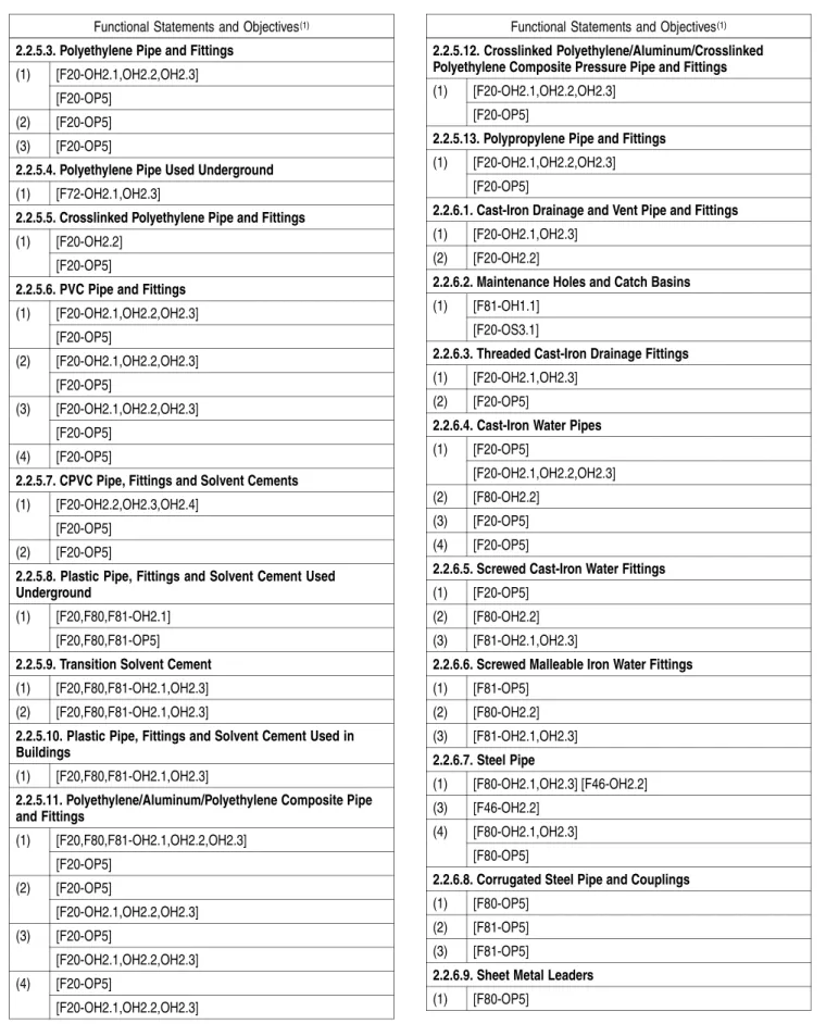
Table 2.8.1.1.
Objectives and Functional Statements Attributed to the Acceptable Solutions in Part 2
Forming Part of Sentence 2.8.1.1.(1)
Functional Statements and Objectives(1)
2.1.2.1. Sanitary Drainage Systems (1) [F72-OH2.1]
[F72-OH2.1] (2)
[F72-OP5]
2.1.2.2. Storm Drainage Systems (1) [F72-OP5]
2.1.2.3. Water Distribution Systems (1) [F46-OH2.2]
2.1.2.4. Separate Services
(1) [F71-OH2.1,OH2.3] [F70-OH2.1] 2.1.3.1. Lighting and Ventilation Requirements
[F40-OH1.1] Applies to the requirement for ventilation. (1)
[F30-OS3.1] Applies to the requirement for lighting. 2.1.3.2. Accessibility
[F40-OH2.1] [F41-OH2.4] [F71-OH2.3] [F82-OH2.1,OH2.2,OH2.3,OH2.4] [F71-OH2.3] [F81-OH2.4] (1) [F81-OP5] 2.2.1.1. Exposure of Materials [F80-OH2.1,OH2.2,OH2.3,OH2.4] (1) [F80-OP5] [F80-OH2.1] (2) [F80-OP5] 2.2.1.2. Restrictions on Re-Use (1) [F70-OH2.2] 2.2.1.5. Withstanding Pressure [F20,F81-OH2.1,OH2.3] [F46-OH2.2] (1) [F20-OP5]
2.2.1.6. Working Pressure of a Water Service Pipe [F20,F81-OH2.3] (1) [F20-OP5] 2.2.2.1. Surface Requirements (1) [F41-OH2.4] 2.2.2.2. Conformance to Standards [F80-OH2.1,OH2.4] (1) [F80-OS3.1] 2.2.2.3. Showers [F80-OH2.1] (1) [F80-OP5] [F80-OH2.1] (2) [F40-OP5] Table 2.8.1.1. (Continued)
Functional Statements and Objectives(1)
(3) [F45-OH2.1] (4) [F45-OH2.1]
2.2.2.4. Concealed Overflows (1) [F41,F81-OH2.1,OH2.4]
2.2.2.5. Water Closets in Public Washrooms (1) [F30-OH2.1,OH2.4] 2.2.3.1. Traps (1) [F81,F40-OH1.1] [F81-OH1.1] (2) [F81-OP5] [F81-OH2.1,OH2.3,OH2.4] (3) [F81-OP5] (4) [F81-OH1.1] (5) [F81-OH1.1] 2.2.3.2. Interceptors (1) [F81-OH2.1,OH2.3,OH2.4] (2) [F81-OH2.1,OH2.3,OH2.4] [F46-OH2.2] [F81-OH2.1] (3) [F81-OP5] 2.2.3.3. Tubular Traps [F82-OH2.1,OH2.4] (1) [F82-OP5]
2.2.4.1. T and Cross Fittings (1) [F81-OH2.1,OH2.4] (2) [F81-OH2.1,OH2.4] 2.2.4.2. Sanitary T Fittings (1) [F81-OH2.1,OH2.4] [F81-OH2.1,OH2.4] (2) [F81-OP5] 2.2.4.3. 90° Elbows (1) [F81-OH2.1,OH2.4] (2) [F81-OH2.1,OH2.4] 2.2.5.1. Concrete Pipe and Fittings (1) [F20-OH2.1]
(2) [F20-OH2.1] (3) [F20-OH2.1] (4) [F20-OH2.1] (5) [F20-OH2.1]
2.2.5.2. Vitrified Clay Pipe and Fittings (1) [F20-OH2.1]
(2) [F20-OH2.1] (3) [F20-OH2.1]
Division B 2-57 Amended Page