Active Control of Underwater Propulsor Noise Using Polypyrrole
Conducting Polymer Actuators
by Daniel F. Opila
B.S., Mechanical Engineering (2002) Massachusetts Institute of Technology
SUBMITTED TO THE DEPARTMENT OF MECHANICAL ENGINEERING IN PARTIAL FULFILLMENT OF THE REQUIREMENTS FOR THE DEGREE OF
MASTER OF SCIENCE IN MECHANICAL ENGINEERING AT THE
MASSACHUSETTS INSTITUTE OF TECHNOLOGY JUNE 2003
© 2003 Massachusetts Institute of Technology. All rights reserved.
Signature of Author:
Department of Mechanical Engineering May 10, 2002
Certified by:
Dr. Anuradha Annaswamy Principal Research Scientist
Thpcie C""'Nor
Accepted by:
Am A. zionin Professor of Mechanical Engineering Chairman, Department Committee on Graduate Students
MASSACHUSETTS INSTITUTE
Active Control of Underwater Propulsor Noise Using Polypyrrole
Conducting Polymer Actuators
by Daniel F. Opila
Abstract
The field of biomimetics seeks to distill biological principles from nature and implement them in engineering systems in an effort to improve various performance metrics. In this paper, a biology-based approach is used to address the problem of radiated propulsor noise in underwater vehicles using active control. This approach is one of "tail articulation" of a stator blade, which is carried out using a suitable strategy that effectively alters the flow field impinging on a rotor downstream and in turn changes the radiated noise characteristics of the rotor blades. This articulation is accomplished by attaching an actuator at the trailing edge of an upstream stator blade and modulating it using a control strategy. Two actuation methods are used to articulate the stator-tail: a conducting polymer actuator and a stepper motor. An encapsulated conducting polymer (CP) actuator based on polypyrrole is designed, fabricated, and tested for operation in water. This CP actuator is shown to alter the flow field in an open channel water tunnel. Flow measurements are also conducted using a motor controlled articulation to yield greater actuator authority. Wake deficits are reduced up to 60% with trailing edge articulation, and the corresponding radiated noise from the propulsor is predicted to drop by 5-10 dB. Wake deficit reduction occurs most effectively with Strouhal numbers of 0.25 to 0.35, the range previously reported by others to be the operating regime of propulsion efficiency in swimming fish.
Thesis Supervisor: Dr. Anuradha Annaswamy
Table of Contents
A cknow ledgem ent...5
1. Introduction ... . 6
2. E xperim ental T estbed ... 8
3. A ctuation M ethods... 10
3.1 Shape Memory Alloy Wires... 11
3.2 Conducting Polymer Actuators...14
3.2.1 Growing Polypyrrole...14
3.2.2 Creating the Bilayer Actuator...25
3.2.3 Constraining the Curl to Yield Desirable Motion...33
3.2.4 Water Encapsulation...39
3.3 Stepper M otor... 52
4. A ctuator Perform ance...53
4.1 Polymer Current Draw During Actuation...53
4.2 Polymer Deflection Performance...56
4.3 Stepper Motor Authority...58
5. Actuator Impact on Flow Field*...58
5.1 Baseline Measurements...60
5.2 Impact of CP-based Articulation...61
5.3 Impact of Stepper Motor Articulation...63
5.4 Conducting Polymer vs. Stepper Motor Performance...70
6. Projected Impact on Stealth*...71
6.1 Motivation/Noise Model...71
6.2 N oise Predictions...74
6.3 Frequency Domain...77
7. Summary and Concluding Remarks...81
8. R eferences... 84
* Author's Note: Many of the figures in sections 5 and 6 are difficult to present in the black and
white required in this work. The reader is invited to read reference [24] for a presentation of the same material in color.
Table of Figures
Figure 1: Wake Deficit Noise Generation ... 6
Figure 2: Tail Articulation for Radiated Noise Alteration... 7
Figure 3: E xperim ental T estbed... 9
Figure 4: Tail articulation via stepper motor. ... 10
Figure 5: SMA wires are used to articulate a "tail" ... 12
Figure 6: D eposition setup ... 15
Figure 7: The Glassy Carbon Crucible is secured in the lathe... 18
Figure 8: The polishing stick is mounted on the lathe... 19
Figure 9: The crucible can be polished with a buffing wheel... 20
Figure 10: The polypyrrole film is removed from the crucible ... 24
Figure 11: The polymer films are laminated into bilayers... 27
Figure 12: The bilayer baking fixture ... 28
Figure 13: The second lead wire can be straightened in place. ... 32
Figure 14: Desired motion of the bilayer... 34
Figure 15: Slitting the bilayer to constrain curl ... 35
Figure 16: Carbon Fiber strips are glued to the actuator ... 37
Figure 17: The bilayer is encased in a plastic "envelope"... 44
Figure 18: A needle is used to draw vacuum in the envelope. ... 45
Figure 19: Plastic encapsulation using spray adhesive ... 50
Figure 20: Current draw performance of "inside-in" vs. "outside in" bilayers ... 55
Figure 21: Deflection performance of Stiffened vs. Sliced Bilayers ... 57
Figure 22: Baseline streamwise velocity U' at 80% of chord length ... 61
Figure 23: Flow alteration due to bilayer oscillation at 1 Hz. ... 62
Figure 24: Wake deficit U' with move profile 1... 64
Figure 25: Wake deficit U' with move profile 2... 65
Figure 26: Wake deficit U' with move profile 3... 66
Figure 27: Wake deficit U' with move profile 4... 67
Figure 28: Wake deficit reduction as a function of Strouhal number... 69
Figure 29: Minimum motion for wake deficit reduction ... 70
Figure 30: Radiated Noise for move profile 2... 75
Figure 31: Radiated Noise for move profile 4 ... 76
Figure 32: Noise spectrum for uncontrolled ... 77
Figure 33: Sensitivity of radiated noise to control phase... 80
Acknowledgements
This work is supported by the Office of Naval Research (N00014-02-1-0036), through the Biorobotics and Biomaterials program.
I would like to thank my advisor, Dr. Anuradha Annaswamy, for her exceptional advice, assistance, and guidance during my research. I gratefully acknowledge the assistance of Professor Ian Hunter, Dr. John Madden, Peter Madden, Patrick Anquetil, and Brian Schmid in the Bioinstrumentation laboratory in the polymer growing and synthesis techniques which were central to the actuator development reported in this work.
1. Introduction
Swimming and flying animals exhibit rapid hovering, maneuvering, and cruise characteristics that surpass man's best achievements to date. These animals have been studied in an attempt to replicate their remarkable maneuvering capability [1-6] in small underwater vehicles. However, these maneuvering capabilities make extensive use of unsteady hydrodynamics, which are not easily applicable to the conventional steady-state hydrodynamics on which most current engineering vehicles are built.
Noise production is a constant concern in some types of underwater vehicles, especially those for military applications. Direct radiation is a major source of this noise and comes from several sources, including fluctuating forces, fluctuating volumes, and turbulence [7]. The operation of a propulsor in a non-uniform wake causes fluctuating thrust and side forces.
V
Stator
Vout
Propeller Blade
RW
Wake Deficit
Figure 1: Wake Deficit Noise Generation
Specifically, a stator or guide vane produces a wake deficit in a uniform flow, as shown in figure 1. This wake deficit generates unsteady forces when it is incident on the rotor blade, generating noise.
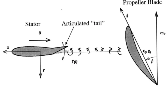
Active control is the modulation of relevant parameters of a process in order to improve its performance. The proposed actuation method is a tail articulation that introduces unsteady hydrodynamics which alter the unsteady forces downstream and thus the radiated noise. The proposed control surface is the trailing edge of the stator, similar to an aileron on a plane. The proposed actuation and its effects are illustrated in figure 2
Propeller Blade
Stator
Articulated "tail"
U raor
Figure 2: Tail Articulation for Radiated Noise Alteration
Many available actuation methods could provide this articulation, including electromagnetics, piezoelectrics, and fluid systems. The specific method investigated in this work uses polypyrrole, a conducting polymer. The attractive features of such a method are its potential in realizing high power to mass ratio, high stresses, and low self noise production. Shape memory alloy (SMA) wires were also investigated, but were not used in favor of the polymers.
The specific conducting polymer material used in this work is polypyrrole, which like other conducting polymers, undergoes volumetric changes that allow it to perform as an artificial
muscle [8]. This motion is caused by ion exchange with a surrounding electrolyte and yields stresses as high as 5 MPa with strains of 1-3% [8-12].
For tail articulation, the CP-based actuator is fabricated from polypyrrole using methods developed by MIT's Bioinstrumentation Lab [8,11,12]. The general actuator design is altered to suit the demands of this particular application. The actuator is fabricated 17 x 40 mm in size and constrained to curl only along its narrow dimension, the desired performance for this application. The polypyrrole actuator is encapsulated in plastic to allow immersion and operation in water. The operation of the actuator is tested and optimized for operation in water.
A benchtop open-channel water tunnel is used to study the flow around a stator with an articulated tail. The wake deficit is measured and compared for different types of tail articulation. Noise production is predicted by simulating a rotor blade passing through the stator wake.
In what follows, section 2 discusses the experimental setup. Section 3 discusses three actuation methods investigated and fabricated to provide tail articulation: Shape memory alloy wires, conducting polymers and the stepper motor. The bandwidth and authority of these actuators in discussed in section 4. The experimental results of the flow testing are presented in
section 5. Section 6 deals with the theoretical noise production and how it can be controlled.
2. Experimental Testbed
Experiments were conducted in a small open channel water tunnel to study how the flow field can be changed by trailing edge articulation. An open channel water tunnel is used because of its simplicity; the purpose of this work is to generate proof of concept. The water tunnel (Armfeld, Inc.) used in this work has a test section 40 cm long in the streamwise direction, 25
cm wide, and 4 cm deep. This tank is capable of speeds from 1-7 cm/s. These experiments were all conducted when operating at a constant 4 cm/s. A stator based on the NACA 0012 profile is used. The stator is 9 cm long with an articulated tail section 1 cm long, for a total chord length of 10 cm. This yields a Reynolds number of 4000. Velocity measurements were taken .8 chord length (8 cm) downstream from the stator assembly, as shown in figure 3.
Figure 3: Experimental Testbed.
To conduct measurements on the flow field, a hot film anemometry probe is mounted on a linear motion stage that spans the width of the tank downstream of the stator, allowing the probe to be moved across the tank.
Tail articulation is provided either by a conducting polymer actuator or a stepper motor attached to an aluminum tail section. The conducting polymer actuator (see section 3.2) is clamped in a groove machined in the back of the stator acts as the articulated tail, as shown in the
figure. Two wires attached above the water line provide electrical power for the actuator.
The stepper motor and aluminum tail are used in place of the polymer bilayers for repeatability and to explore operation beyond the capability of the polymer (see sections 3.3, 5.3). The stepper motor is mounted out of the water directly above the tail pivot point, as shown in figure 4.
Driveshaft Water Line
Stator -AArticulation
--- lumninumn
Flow . "tail"
Figure 4: Tail articulation via stepper motor.
The stepper motor directly drives a shaft attached to the aluminum tail to provide articulation.
3. Actuation Methods
Three different actuation methods were investigated during the course of this work. Shape memory alloy (SMA) wires were used as a first attempt at creating a biomimetic actuator (Section 3.1). Conducting polymers then replaced the SMA wires as the actuation method of choice due to their high stresses, power to mass ratios, and low self noise generation (Section 3.2). As the conducting polymer actuators have limited bandwidth, a stepper motor attached to an aluminum tail is used to study tail motions at higher speeds. (Section 3.3)
3.1 Shape memory alloy wires as actuators
The first attempts to build an actuator for this application used shape memory alloy wires. These wires are made of special alloys that contract when heated. The alloy undergoes a phase change at some transition temperature. The new crystalline structure of the metal is more compact, causing the wire to contract and generating large stresses in the wire. When the wire cools back down below the transition temperature, the alloy returns to its original phase and the wire can be pulled back to its original shape without much effort. To make use of this effect in an application, the wire is actuated by passing an electrical current through the wire. Resistance heating raises the temperature of the wire above the transition temperature, and the wire contracts generating a relatively large force. After the current is turned off, the wire cools and can be stretched back into position by a spring.
The advantages of these wires include very high power to weight ratios, high stresses, and high forces. However, several factors limit the usefulness of this technology. The maximum usable strain the wires can usually produce is around 4%, with a few applications producing strains as high as 7%. This small strain necessitates the use of motion amplifying devices. In addition, after the wires have actuated and cooled, they must be stretched back to their original length by some external force. This stretching process requires forces on the order of 25% of the pull force of the wire and proceeds much more slowly than the original contraction, usually requiring .5-3 seconds while the contraction can take place in milliseconds. The final major difficulty with SMA wires is heat production. The wires must be heated above their transition temperature and then cooled back down. This heat transfer is the major factor that limits the actuation speed in most applications. Moving the heat around rapidly is difficult and that heat must also be transferred out of the overall device.
An actuator was built using SMA wires to evaluate their feasibility for this application and to gain experience with an actuator of this geometry before attempting to build one with conducting polymers. The SMA wires and polymers have similar strain potentials, 4% and 3% respectively, that cause similar design considerations with both technologies. A scale model of a stator was created with a matching trailing edge "tail" that would be actuated by the SMA wires
as shown in figure 5.
Contracting SMA Wire
Anchor Pins
Articulated "Tail"
Stretching SMA Wire
Segment
Figure 5: SMA wires are used to articulate a "tail".
The stator is made of an aluminum epoxy that is nonconductive and easily machineable. The tail is attached to the stator with a hinge. Two attachment points for the wires are mounted to the tail. These attachment points include pins as shown in the figure, or tiny eyelets. The pins or eyelets were attached to the tail by drilling tiny holes in the tail and press fitting them in place. Epoxy can also be used to hold the attachment points instead of the press fit. The wire attachment points on the stator are mounted in the same fashion. The wires have loops at either end created by clamping the wire to itself. These loops are passed around the mounting pins or through the eyelets. The two wires are then actuated independently to pull the tail to one side or the other. After a wire has been activated, the opposing wire pulls it back to its original position. Overall, this setup worked marginally well in air and water, but had some difficulties.
Perhaps the most difficult aspect of this particular actuator setup is the small strains produced by the wires. Wires of the length in the figure, 4" long, produce only .16" of deflection. This could be a usable amount, but any slop in the apparatus renders this deflection unusable. One major source of slop was the wires themselves. The wires were fixed in place by looping them around mounting points. This is the method recommended by the manufacturer because the wire is extremely difficult to mount in other ways. This mounting difficulty stems from the behavior of the wire itself; as the wire contracts, it also experiences an expansion in its diameter. These changes in the wire shape, coupled with the high forces produced, render most clamping or gluing tenuous at best. Unfortunately, the loops are a major source of slop in the apparatus. When the wire is relaxed, it has some intrinsic stiffness and does not want to bend in a small radius. This creates loops that are more rounded. When the wire is activated, the forces produced pull the loop into two straight wires. Though small, the difference in length between a stretched and unstretched loop can waste much of the available deflection. Therefore, the loops were made
as small as possible, which complicates the manufacturing process.
The wires are also difficult to mount. As discussed previously, the most successful mounting method used was to loop the wires. This worked well, but with the larger diameter wires that generate more force, the clamps had a tendency to slip. Providing that loop with a mounting point was also difficult. The forces generated by these wires are quite large and most mounting methods for something of such a tiny size are not equipped to handle those loads. Methods using adhesives failed, and mounting points had to be machined into the apparatus as previously described. This process was complicated by the tiny size of the parts and mounting pins.
Overall, the SMA wires are a very viable technology for certain applications, but not this one. This apparatus could certainly be improved with a better hinge and more devices, such as springs, to reduce the slop in the mechanism. However, certain limitations in the SMA technology limit its usefulness in this application, most notably the large power consumption. An actuation technology that exhibits similar performance characteristics to the SMA but with lower power consumption would be ideal. Conducting polymers are an emerging technology with great potential, although they are very much on the cutting edge and not as developed as the SMA technology. Thus conducting polymers were investigated to determine their suitability for this
application.
3.2 Conducting Polymer Actuators
The process of creating a conducting polymer actuator involves four major steps. The polypyrrole is first synthesized as a thin film (section 3.2.1). The thin films are then fabricated into a bilayer actuator capable of motion (section 3.2.2). These bilayers must be constrained to perform according to the requirements of this application (section 3.2.3). Finally, the polymer bilayers are encapsulated in plastic to allow them to function in water (section 3.2.4).
3.2.1 Growing Polypyrrole: 3.2.1.1 Introduction
The polypyrrole itself is "grown" by a polymerization reaction on a glassy carbon crucible (beaker) using the methods as previously described by others [16, 21, 22]. The glassy carbon crucible is immersed in a solution containing the pyrrole monomer as shown in figure 6.
To Potentiostat
Glass Beaker
Copper
Sheet
Glassy Carbon
Crucible
Pyrrole Monome
Solution
Figure 6: Deposition setup
A thin copper sheet surrounds the crucible (without contact) to serve as the counter electrode. A potential is applied across the glassy carbon and the counter electrode. This causes the pyrrole monomer in solution to polymerize on the glassy carbon.
3.2.1.2 Initial Setup
Glassy carbon is used because of its conductivity and extremely smooth surface, which allows for easy removal of the polymer to yield polymer films. In addition, the glassy carbon can be polished to obtain the optimal surface roughness for growing the polymer. By trial and error, it was found that the optimal surface roughness is somewhere between the "new" and "used" (after one deposition cycle) conditions, so the glassy carbon was polished between growth
cycles. (see section 3.2.1.5) The glassy carbon crucible used is approximately 75 mm in diameter and 80 mm high.(available from HTW, Germany) The solution is contained in a 1000ml glass beaker. The copper sheet is placed around the inside circumference of the large glass beaker from top to bottom. The outer beaker is large enough to allow the glassy carbon beaker to sit inside with about 2 cm clearance between the glassy carbon and the copper to prevent electrical shorts. The electrical connection is applied through alligator clips attached to the top of the glassy carbon and the top of the copper sheet.
3.2.1.3 The solution:
The conducting polymer material that actually causes actuation is hexafluorophosphate-doped polypyrrole. These films are grown from a solution of .06 M purified pyrrole monomer and .05 M tetraethylammonium hexafluorophosphate in propylene carbonate, using the methods of Yamaura [21] as previously described by others [16,22]. The pyrrole monomer is prepared by distillation and stored under nitrogen.
3.2.1.4 Initial Preparation
Before starting a growth cycle, all components (glassy carbon crucible, glass outer beaker, and copper) are washed with Alconox chemistry soap and rinsed three times in tap water, then three times with distilled water. In addition, the glassy carbon crucible itself requires special preparation. First, the crucible is washed and scraped with a razor blade to remove any residue from the previous deposit and to allow handling without gloves. The beaker must then be polished.
3.2.1.5 Polishing Methods
When the crucible is new, its surface is perfectly smooth, but it produces bad polymer films. When the polymerization reaction occurs, there is insufficient surface roughness for the polymer to adhere to the crucible. The films grow, but bubbles and wrinkles form where the film does not adhere to the crucible. The films are then very easy to remove, almost falling off, but they are rough and uneven. The smooth, even films produced on crucibles that have been used several times and have a small amount of surface roughness are much more suitable for actuator construction.
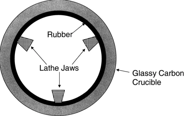
The optimal surface roughness for growing polymer films was found to be slightly smoother than a crucible that just completed a growth cycle, so the crucible is polished. The crucible is mounted on a lathe using a strip of 1/8" thick by 1 inch wide rubber as shown in figure 7.
Glassy Carbon
Crucible
Figure 7: The Glassy Carbon Crucible is secured in the lathe with a strip of rubber
The rubber strip is placed inside the crucible at the top, and covers the top one inch of the inside circumference of the crucible. The jaws of the lathe chuck are then inserted inside the crucible and gently expanded to press against the rubber. Great care must be taken to use as little clamping force as possible to hold the crucible. The 3 jaws can visibly deform the crucible quite easily, and even fracture it with very little tightening force. The force used must be just enough to hold the crucible against a gentle push at the free end of the crucible. The lathe was run at 200 rpm, and the direction was such that the operator side of the crucible was traveling down.
3.2.1.5.1 Hand Polishing using polishing stick
The first method of polishing used a "polishing stick" intended for hard metals such as steel. The edge of the polishing stick was gently pressed against the operator side of the crucible and slowly moved back and forth across the crucible to give a uniform finish. Care must be taken
not to press too hard, or bits of the polishing stick break off and attach to the crucible leaving a residue which must be removed. After polishing, any residue from the polishing stick can be removed by pressing firmly with a clean paper towel; this is much more efficient that attempting to polish off the globs of polishing compound. This method took approximately 20 minutes for a good surface finish.
3.2.1.5.2 Autonomous Polishing using polishing stick
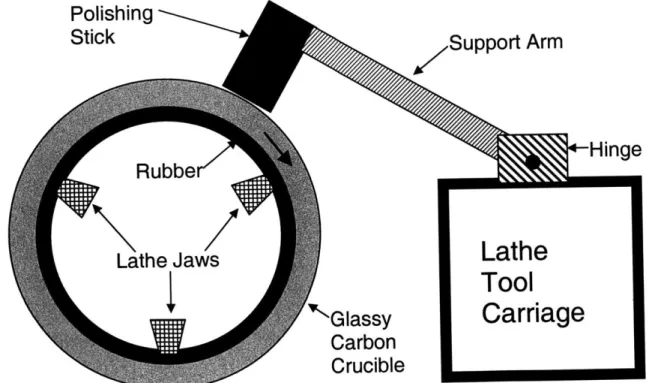
The second polishing method is effectively the same but more consistent and less labor intensive. The polishing stick and lathe setup are the same, but the polishing stick is mounted to the lathe tool mount as shown in figure 8.
Polishing
StickSupport
Arm
Rubbe
Hinge
Lathe Jaws
Lathe
Tool
Glassy
Carriage
Carbon
Crucible
Figure 8: The polishing stick is mounted on the lathe tool carriage for automatic polishing.
The polishing stick is mounted so that its own weight gently pushes it against the rotating crucible. More force can be applied by using a heavier or longer support arm. The lathe carriage
can then be moved autonomously from one end of the crucible to the other very slowly. This yields a uniform, consistent surface finish without requiring an operator to physically hold the polishing stick.
3.2.1.5.3 Buffing Wheel Polishing
The third polishing method is faster and yields a better finish than the other methods, so it was used most often. The lathe setup is again the same, but instead a buffing wheel attached to a drill is used as the polishing tool as shown in figure 9.
Rub
.
.... ....
G...ssy..Carb.n
C
..
ru...
. b.
..
Figue 9:The rucile cn bep....ed th ..bufing .. ..ee
A bffig cmpundis ppledto he hel, he ri....a.i.aed.an.th.spnnng.hee.i genty pessd aaint te rtatng rucble Tw .diferet.bffig.. mp. ndswer..sd,.
jeweler's rouge (intended for soft metals) and a compound intended for steel and harder metals. The jeweler's rouge produced a good finish, but as it is intended for softer metals, it polishes the relatively hard glassy carbon slowly. The steel buffing compound worked more quickly than the jeweler's rouge and yielded a similar finish, making it the optimal choice. The buffing wheel is cotton (available from McMaster) and intended for delicate work. The buffing wheel setup allows for faster polishing of a much larger area compared to the polishing stick, making this method as a whole much faster; it requires only 5 minutes for a good surface finish. In addition, given enough time, the buffing wheel could return the crucible to a surface finish similar to when it was new. This was not usually done due to the poor films generated with a new crucible.
3.2.1.6 Final Setup after polishing
After the crucible has been polished, it is again washed using the method previously described. After this point, the crucible is only handled using gloves to avoid depositing skin oils on the glassy carbon. The entire glassy carbon crucible is conductive; any portion of it exposed to the pyrrole monomer solution during deposition will form a deposit of polypyrrole. Therefore, portions of the crucible are covered in Kapton (polymide) tape (available from McMaster) to prevent the formation of polypyrrole. Kapton is used because is chemically stable, adheres well in the cold temperatures during the deposition, and is easy to remove. The bottom of the crucible is entirely covered with tape, and a strip of tape is placed at the top and bottom edges of the crucible; films that form there are of poor quality. Rings of tape are placed around the circumference of the crucible to produce strips of polypyrrole film of a desired width. After the crucible is taped, it is usually rubbed down with a paper towel soaked in acetone to remove any residual oils before placing it in solution.
The final step is to place the crucible and copper in solution in the glass beaker. The copper sheet is first placed inside the empty glass beaker around its circumference. A copper sheet approximately .025" thick is flexible enough to fit into the beaker, but will expand outward tightly against the beaker. The glassy carbon crucible is then placed inside the beaker as well. A steel or lead weight is placed inside the crucible to prevent it from floating in the pyrrole monomer solution. Electrical leads are attached with an alligator clip to the top of the crucible and the top of the copper sheet. The monomer solution is then very carefully poured into the glass beaker around the glassy carbon crucible. The whole assembly is then put in a -40 C freezer and connected to an electrical supply.
3.2.1.7 Deposition
The deposition apparatus is connected to an Amel Model 2051 potentiostat. This instrument can very precisely control the voltage and current during the deposit. The deposition settings can vary within certain limits to yield good polymer films. The voltage across the crucible/copper combination should not exceed about 3.3 volts, or the polymer film begins to degrade. The current density should not exceed 1.25 A/mA2 or the films will form poorly. For this size crucible, that limit is approximately 10 mA. The potentiostat can operate in potentiostatic (constant voltage) or galvanostatic (constant current) modes. In theory, constant current operation yields better films. However, there seems to be no discernible evidence that constant voltage deposition is any different, although extensive testing on the polymer itself was not conducted.
A typical deposition cycle is to run in galvanostatic mode at 10 mA for 12 hours. The potential starts around 1.7 volts and reaches about 2.95 volts at the end of the deposition. A
deposition of this type yields films approximately 20 microns thick. Good quality films have been grown in thicknesses ranging from 10-90 microns. During the polymerization reaction, each electron transferred corresponds to one additional pyrrole monomer added to the polymer chain. Thus, the amount of material deposited, and therefore the thickness of the films, should be linearly related to the amount of charge applied during the deposit. Preliminary results show this is not the case for film thicknesses in the 10-90 micron range. The film thicknesses appear to involve a complex relationship between different deposition parameters.
3.2.1.8 Removing the films
At the completion of a deposition, the electrical supply is turned off and the glassy carbon crucible is removed from the freezer. The crucible is usually allowed to return to room temperature for easier handling. A razor blade is used to remove the films from the crucible. "Extra Keen" razor blades were slightly easier to work with, although they dull faster. Standard single edge industrial blades also perform well. The first step is to cut the polymer along any tape edges approximately 1mm from the tape. When the polymer deposits on the crucible, the edges of the film that are in contact with the Kapton tape are rather uneven. Cutting along the tape edges separates this uneven portion of the film from the smooth sections. Each strip of polymer film can then be removed. The Kapton tape is removed on either side of a strip, and a razor blade is scraped along the circumference of the crucible as shown in figure 10.
Previously Removed Film
Razor Blade
Blade Motion
a
4Scrape
Angle 'a'
Glassy
Carbon
Crucible
Polypyrrole Film
(~20 microns thick)
Figure 10: The polypyrrole film is removed from the crucible with a razor blade
The polymer film can then be peeled off as the razor blade travels along the crucible. The angle that the blade makes with the surface of the crucible, the "Scrape Angle" in figure 10, varies from approximately 20 degrees to 45 degrees. The relative difficulty associated with removing the films varies with each deposit. Films on a rough crucible generally require more force to peel off. As more force is used, the scrape angle increases. This allows to blade to make better contact with the crucible surface and remove any remnants of the polymer. When removing very thin films, more force and a higher scrape angle is used to ensure that the entire film is removed from the crucible. The higher scrape angle also decreases the chances of the blade slipping forward and severing the polymer strip. The scrape angle is lower when using less force to allow the blade to slide easily along the surface of the crucible.
3.2.1.9 Storing the polymer
After removal from the crucible, the polymer is stored in saran wrap with a solution of propylene carbonate (PC) and TEAP. This is the same base solution used to grow the polymer, but without the pyrrole monomer. If left exposed to the air, the PC solution evaporates and the polymer "dries out"; it is no longer saturated with PC. The polymer films have different handling properties when dried out; they are slightly less flexible and have less of a tendency to curl and fold. If again exposed to PC, it will return to something near its original state, but films that undergo this process tend not to perform quite as well.
3.2.2 Creating the Bilayer Actuator. 3.2.2.1 Basic polymer behavior
The polypyrrole films provide the actuation force for the bilayer actuators, and as such are the main component. When activated by a potential source, they contract isotropically via an ion exchange with a surrounding electrolyte. However, the maximum strains available are only
-2% [9-16] at strain rates of up to .1% s1 [9,10] under normal conditions.
These small strains and strain rates necessitate some mechanical amplification to yield useable motion for this application, so a bilayer is used. Two polymer films 20 microns thick are laminated together with a spacer in between to form a bilayer [16-20] (section 3.2.2.3). The small motion of the films relative to each other causes a bending of the bilayer, and a large amplification of the motion of the polymer films. However, this motion amplification causes a proportional loss of force. The bilayers studied in this work are approximately 17x40 mm and 80
microns thick. This yields a bilayer that can bend as much as 180 degrees, but with a .1 N tip force.
Due to the uniform nature of the polymer films, activation of the actuator will cause curl uniformly in all directions. For this application, only one direction of motion is desirable, so the bilayers are constrained to curl in only one direction (section 3.2.3).
3.2.2.2 Gel Electrolyte Composition
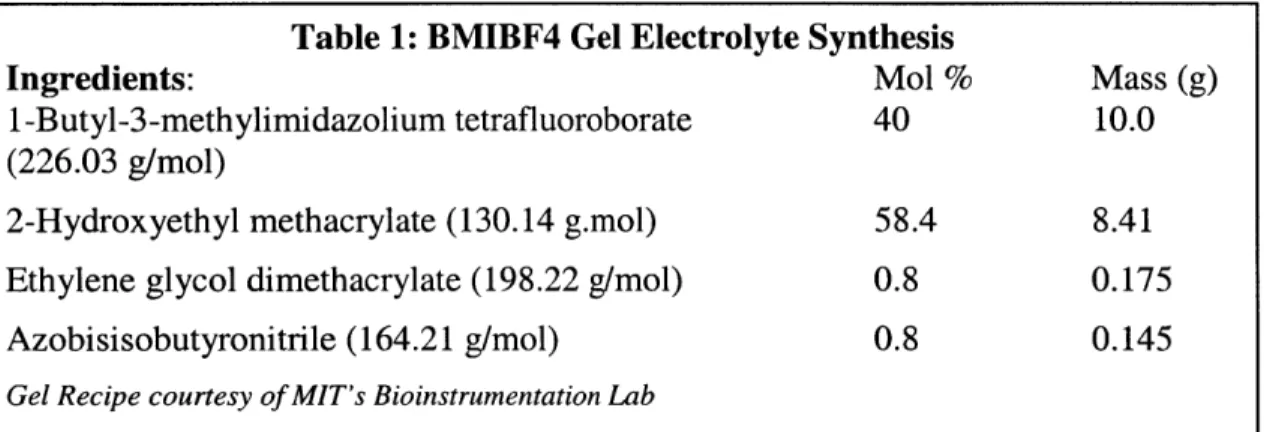
The underlying cause for the motion of the polypyrrole is ion exchange with an electrolyte, so the polypyrrole films must be in contact with an electrolyte to operate. For this application an electrolyte based on an ionic liquid was used as described by Noda and Wantabe [22] as shown in Table 1.
Table 1: BMIBF4 Gel Electrolyte Synthesis
Ingredients: Mol % Mass (g)
1 -Butyl-3-methylimidazolium tetrafluoroborate 40 10.0 (226.03 g/mol)
2-Hydroxyethyl methacrylate (130.14 g.mol) 58.4 8.41 Ethylene glycol dimethacrylate (198.22 g/mol) 0.8 0.175
Azobisisobutyronitrile (164.21 g/mol) 0.8 0.145
Gel Recipe courtesy of MIT's Bioinstrumentation Lab
Table 1: BMIBF4 Gel Electrolyte Synthesis
This electrolyte is a liquid that forms a gel when baked at 85 C for 12 hours. The gel is applied to the desired surfaces, clamped, and then baked as described in section 3.2.2.3. This ionic liquid electrolyte yields better polymer performance and lifetime when compared with other electrolytes, such as those based on organic solvents.
3.2.2.3 Building actuators
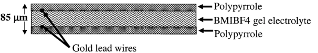
To fabricate an actuator, the challenge is to convert the contraction of the polypyrrole films into some kind of useable motion. The polypyrrole films exhibit strains of about 3%, and usable strain rates on the order of .05% s-1 [9-16] In order to use this motion for this application, the polypyrrole films are fabricated into bilayers of two opposing polymer films laminated together, as shown in figure 11.
+-Polypyrrole
85 In +-BMIBF4 gel electrolyte
rPolypyrrole Gold lead wires
Figure 11: The polymer films are laminated into bilayers
The polypyrrole films are separated by a layer of lens paper soaked in the BMIBF4 gel electrolyte. The lens paper serves as a mechanical spacer between the two polypyrrole films and as a sponge to hold the gel electrolyte in place. This spacing allows two sheets of polymer to work as a lever. When one film contracts and the other expands, they apply a torque and cause the bilayer to curl. The length of the bilayer is much larger than its thickness; this causes an amplification of the motion of the polymer films. A very small displacement of the polymer films causes a large tip deflection. This amplification is the main reason bilayers are used in this application. Unfortunately, while the displacement is amplified, the force available at the tip is proportionately reduced. The available tip force for actuators in this work ranged between 5 and 100 millinewtons. This was sufficient to allow the actuator to move in water, but the tip force was insufficient to perform most tasks. The tip force was insufficient to be detected by a bare finger in most cases.
The bilayer fabrication begins with the baking fixture. Two sheets of Teflon are paired with two sheets of steel to yield a fixture that can compress the bilayers without sticking to them, as shown in figure 12. Clamps BMIBF4 gel Polypyrrole electrolyte ---- ---- --- ---- --- T eflo n
Gold lead wires
Steel
Figure 12: The bilayer baking fixture
The bilayer in figure 12 is built from the bottom up. First, one Teflon sheet is placed on one steel sheet to form the base of the fixture. Two pieces of polymer film are cut to the desired bilayer size, and one piece is placed flat on the Teflon. Care must be taken to ensure that the film lies flat without wrinkles or folds. Depending upon the film and the way it was stored, certain films exhibit a great tendency to curl. By using several drops of the TEAP solution (the solution used to store the polymer) between the polymer and the Teflon, a suction effect can be created that will stick the polymer flat against the Teflon.
Sometimes a few drops of the BF4 electrolyte gel are placed on the Teflon side of the polymer film. This is in an attempt to prevent a preferential curvature of the bilayers once they are complete. After removal from the oven or after a few cycles of activation, some bilayers develop a preferential curvature; their neutral position is not zero curvature. This phenomenon is
not fully understood, but one possibility is that the polymer films are not exposed to the same amount of BMIF4 electrolyte gel. When the bilayer is clamped, some of the electrolyte from the middle layer squeezes out and contacts the outside of the polymer films in an unpredictable manner. This unequal exposure to the electrolyte could cause the polymer films to contract unevenly. By adding additional gel to the outside in the assembly step, both polymer films are uniformly exposed to the electrolyte.
The effect of the electrolyte itself is visible to the naked eye. When the BF4 electrolyte gel is first added to a polymer film, it will begin to curl in one direction even without an applied potential. The ions activate one side of one film, causing the film to curl. If the other side of the film is then exposed to the electrolyte, the film will relax back to a flat state now that both sides
are exposed to the same electrolyte.
After the first polymer film is lying flat, an electrical lead is inserted. Gold wires of .003" or .004" diameter are used. There is not a large difference between the two sizes, but the .004" diameter wire is slightly stronger and more durable in making the electrical connections to the power supply. However, the .003" wire is smaller and fits inside the bilayer more easily. Whichever wire is chosen, one piece approximately 5" long is laid along one long edge of the polymer film. One end of the wire should rest close to one short edge of the polymer film, with the rest of the wire extending off the polymer film. This is not as easy as it sounds, the wire is small, delicate, and has a natural curvature from the wire spool. Lightly stretching the wire segment can remove some of the natural curvature from the wire spool. If the wire is close to its final position, the wire can be straightened with tweezers after the next step, as described in the next 2 paragraphs. After the lens paper is saturated with the electrolyte gel, it becomes almost transparent. The wire is clearly visible beneath it and is help in place by the lens paper and gel
combination. It is now a simple matter to use tweezers to pull the wire into position, where it will stay.
After the wire is fixed in place, the electrolyte layer must be created. A piece of lens paper (Kodak or VWR) is cut slightly larger than the polymer film and placed over it and the wire. The size of the lens paper is not important because it will be trimmed away eventually, but electrolyte gel is wasted by being absorbed into the excess paper. With the lens paper in place, a glass stirring rod is used to place drops of the electrolyte gel onto the lens paper. The lens paper absorbs the gel and sticks to the polymer film beneath it. Enough electrolyte gel should be used to thoroughly saturate the lens paper. A puddle of electrolyte gel should be barely visible on the lens paper.
With the lens paper saturated in electrolyte gel, some provision is now made to prevent short circuits between the wires. An additional piece of lens paper is cut to the length of the polymer film and about 5 mm wide. This piece is place over the path of the electrode wire. It serves as an additional insulator between the two electrode wires, the most likely place for a short circuit. A piece of thin mylar film can also used in place of the additional lens paper to provide a stronger insulator. Both surfaces of the mylar should be roughened with fine sandpaper before placing it in the bilayer. The smooth surface of the mylar prevents the polymer films from adhering to it, yielding a bilayer that delaminates.
After the additional short circuit protection, the second lead wire should be added. A piece of wire similar to the first electrode is laid in a similar position on top of the short circuit protection. Getting this wire to stay in place is also a difficult task, just like the first electrode. Unlike the first electrode, there is no lens paper to hold this wire in place. An extra drop of electrolyte gel can aid in getting one end of the wire to stick. If the wire is close to its intended
position, after the second layer of polymer film is added (the next step), the film can be peeled back slightly to stretch the wire to its desired position as shown in figure 13 below. After the electrode wire is in place, the second polymer film can be added. This film must lay flat with no folds or wrinkles over the rest of the actuator. Great care must be taken so that the lower layers are not disturbed during the addition of the last layer. Once the top polymer film is in place, the bottom corner of the bilayer can be lifted to allow access to the second lead wire as shown in figure 13.
Pull wire here to straighten
t
Gold Lead Wire
Top polymer film
Gold Lead Wire
Pull wire here to straighten
Figure 13: The second lead wire can be straightened in place.
Two pairs of tweezers are used to grasp the wire at either and pull it into position. The wire runs parallel to the inside edge offset about 3 mm. By only peeling back a corner to grasp the wire, the rest of the polymer film holds the wire in place. When the wire is released, it maintains its position and the corner of the polymer can be folded back in place.
After the last layer is added, the second Teflon sheet is added followed by the second steel sheet. The two steel sheets are clamped together with "C" clamps, squeezing the bilayer together. The whole apparatus is then placed in an oven at 85 C for at least 12 hours to cause the
gel to cross-link and change from a liquid to a very flexible solid. The bilayer should not be left in the oven for more than 24 hours or the polymer films may begin to degrade.
The apparatus is removed from the oven after 12 hours and allowed to cool so that it may be handled. The clamps and steel plates are removed, and the Teflon sheets are carefully peeled apart to expose the bilayers. The different layers that make up the bilayer are all of slightly different sizes and thus overlap, leaving excess material protruding from the bilayer that should be trimmed away. The bilayer is placed on a glass plate or other suitable surface that will not be damaged by a razor blade. A glass slide is placed on the bilayer to hold it in place and to provide a straight edge for trimming. A razor blade is then used to cut the bilayer along the edge of the slide. The four sides of the bilayer are trimmed to yield a clean rectangle, but the area around the lead wire must be done carefully to avoid severing the wires.
The bilayer is now ready to actuate. The bilayers are usually tested for performance before being encapsulated. This avoids wasting labor in the encapsulation process on bilayers that do not work for some reason.
3.2.3 Constraining the curl to yield desirable motion
The major difference between the bilayers in this work and those in other research is their preferential curl. For this application, the bilayers should curl along their narrow dimension as
Curl
Stator
Polymer Articulated
Biomimetic "Tail"
Flow
Figure 14: Desired motion of the bilayer.
This is not the natural motion of the bilayers; the polymer actuates uniformly in both directions. Therefore, the bilayers will curl in all directions. Some provision must be made to force the bilayer to curl in the desired direction as shown in figure 14 above. Two methods were devised and tested to solve this problem, cutting slits in the bilayer (slitting), and adding stiffening strips.
3.2.3.1 Slitting to control curl
To prevent the bilayer from curling in one direction, the logical solution is to relieve the stress in that direction. To accomplish this, slits are made across the narrow dimension of the bilayer to relieve the stress in the long dimension as shown in figure 15.
Gold Lead Wires
Figure 15: Slitting the bilayer to constrain curl
These slits are spaced -3 mm apart and extend to within 3 mm of the long edges of the bilayer. The slits prevent large scale deflections along the long axis of the bilayer. Each 3 mm wide strip between the slits can still curl along the long axis of the bilayer, but their narrow width means this curvature yields only small displacements. The slits effectively make one bilayer into about twenty smaller bilayers with large aspect ratios that are attached at the tip. The strips of bilayer left intact along the long edges serve to hold the bilayer together and to hold the individual strips created by the slits in phase. The width of the slits can be altered, but this does not have a large effect as long as the slits are not spaced more than about 6 mm on an actuator of this size. As the slit spacing grows larger, the curvature of the individual strips has a larger effect. The edges of the individual strips along the slits can be seen to bulge out in one direction as the individual strips curl. This has not yet shown to be a problem, but the bilayer looks like a series of ridges and spaces. This inconsistency in the bilayer as it curls could be a problem in some applications.
Overall, the "slitted" bilayers perform well. The motion is smooth and mostly even. For a first attempt, this method works well. However, several problems presented themselves. The
outer long edge (away from the electrode wires) usually became distorted and wavy as it was unable to keep the different individual strips in phase. The slits themselves also caused some difficulty. As the bilayer moves through the neutral position during its actuation, the two sides of the slit visibly get caught on each other. This means an added mechanical resistance, so the bilayer has difficulty moving through the neutral position. During actuation, the bilayer would deflect at a relatively constant speed towards the neutral position, slow down while visibly straining as it moved across neutral, have a sudden burst of speed as it got past the neutral position, then resume its normal speed. This could be a problem, especially for applications that require smooth motion or small displacements around the neutral position.
One other difficulty with the slits is that they cause small electrical shorts. The polymer films are very conductive; this allows them to carry their own electrical supply for activation. Typically, the two polymer films are separated by the lens paper. However, after the slits are made, the two opposing polymer films can brush past each other during actuation across the neutral position, causing a short circuit. The actual amount of current shorted is small compared to that which is driving the bilayer and as such are not noticeable from the power supply. However, the shorts are visible to the naked eye as small sparks or tiny wisps of smoke. Each time the bilayer passes neutral, the polymer films short in one or two places, causing the small wisp of smoke. The polymer then seems to insulate itself. If would appear that the polymer burns itself out at the location of the short as the short occurs. This would explain the puff of smoke. This shorting phenomenon only occurs in the first few minutes of actuation, then slows and
3.2.3.2 Stiffening with carbon fiber/mica
The second method used to force desirable bilayer curl uses mechanical stiffening strips. Several materials are used, most notably carbon fiber and muscovite mica [23]. Strips of material are glued along the long edges of the bilayer using a flexible urethane as shown in figure 16.
Gold Lead Wires
Polypyrrole
Carbon fiber
reinforcement
"Inner" Mounting Edge
--"Outer" Moving edge
(fixed to stator)
Figure 16: Carbon Fiber strips are glued to the actuator to force desirable motion
The urethane is scraped onto the back of the carbon fiber strips in a thin layer. The strips are placed in position on the bilayer and held in place with a light clamping force to ensure a solid bond without crushing the bilayer. This procedure takes place immediately after the bilayer is removed from the oven without taking it completely out of the baking fixture. The top portion of the baking fixture is removed and the bilayer remains flat on the bottom sheet of Teflon. The bilayer is still very flat from being clamped in the oven and is in prime condition for the attachment of the stiffening strips. If the bilayer is removed from the Teflon or actuated first, it tends to develop curl or wrinkles that make it difficult to attach the stiffening strips well.
After the urethane cures, the bilayer is removed from the clamping fixture and trimmed to remove excess material. The bilayer is trimmed to about 2 mm from the edges of the carbon fiber. This yields a rectangular actuator as previously shown in figure 16.
The possibility of adding stiffening strips inside the actuator was also investigated. Several materials were used including carbon fiber, muscovite mica, and mylar. Instead of gluing the strips onto the outside of the bilayer after it has been completed, the strips are inserted inside the bilayer during the manufacturing process. The stiffening strips are inserted between the two outside polymer films. This yields a less complicated actuator, but the bilayers have a tendency to delaminate when using this method. The two sheets of polymer had difficulty forming a good, uniform bond with the stiffening strips in between.
3.2.2.3 Performance Comparison for methods of constraint
The bilayer with carbon fiber stiffening strips performs comparably to the slitted bilayer, with two improvements. The outer (free) edge of the actuator (fig. 16) stays straight, although it might get twisted compared to the inside edge. This is an improvement over the slitted bilayer, which can develop undulations along its length. The stiffened actuator also avoids the short circuits associated with the slits. The carbon fiber reinforced bilayer, like its slitted counterpart, also hesitates when crossing the neutral position as described for the slitted bilayers. This effect is more pronounced if the two stiffening strips are not exactly parallel. See section 4 for a quantitative comparison of the two methods.
3.2.4 Water Encapsulation 3.2.4.1 Goals
One of the most difficult aspects of this design is to run the polymer immersed in water. The bilayers themselves cannot be directly immersed in water for two reasons. The main reason is water intrusion into the electrolyte layer. The polypyrrole films need to be in contact with an electrolyte to activate. The electrolyte in this case is sandwiched between the two polymer films; it also serves as the adhesive to hold the bilayer together. When immersed, water penetrates into the electrolyte layer between the polymer films, preventing actuation and causing delamination of the polymer films. If it were somehow possible to seal the edges of the bilayer to prevent water intrusion into the electrolyte layer, the bilayer would likely run in water but have a limited lifespan, although this theory has not been tested. The bilayers would have a limited lifespan for several reasons. The outer surfaces of the polymer films would be exposed to the surrounding water; this water would likely inactivate some thickness of the outer surface of the film by preventing complete ion diffusion. Also, the water could contaminate the polymer films with other undesirable ions, rendering parts inactive. The polypyrrole itself might also degrade. For these reasons, it is desirable to completely isolate the bilayer.
The forces produced by the bilayers are sufficient to move in water, but not to do much else. Any method of encapsulating the polymer imparts some mechanical resistance to its motion. The main thrust of the encapsulation research is to isolate the bilayer from the surrounding water while allowing it complete freedom of motion. There are necessarily some design tradeoffs, most notably that any method of better protecting the polymer imparts more mechanical stiffness.
3.2.4.2 Coating Encapsulation Methods
Given the goal of allowing complete freedom of motion, the encapsulating layer should be as thin as possible so as to add minimal mechanical resistance. The most obvious way to do this is to coat the actuator itself in a very thin layer of some material. In theory, this idea could provide excellent water protection with minimal mechanical stiffness. However, this method could not reliably protect the actuators in water. Two coating methods were used: paralene [23], a polymer applied in a -15 micrometer thick film by vacuum deposition (section 3.2.4.2.1), and ordinary rubber cement (3.2.4.2.2)
3.2.4.2.1 Paralene Encapsulation
As previously mentioned, the mechanical stiffness of the bilayer is a primary concern. Therefore, the first method attempted used an extremely thin coating method to try and maintain the flexibility of the bilayers by using a vacuum vapor deposition of paralene onto a bilayer [23]. Paralene is a polymer widely used to insulate circuit boards. This paralene layer is approximately 2 microns thick. The bilayer is placed in a vacuum deposition machine and the chamber is pumped down. The solid paralyne is then vaporized and deposits on everything in the chamber, including the bilayer. The lead wires of the bilayer are protected with Kapton tape to prevent them from forming a paralene coating, which would prevent good electrical contact.
In theory, this is an ideal method of encapsulation; the paralene should form a waterproof, durable membrane that is extremely thin and flexible. In addition, the vacuum deposition process should ensure that the entire bilayer, including any cracks or recesses, is covered in a uniform coating.
In practice, this encapsulation method does not work very well in several regards. When the bilayer samples are removed from the deposition machine, they are usually slightly deformed and have some preferential curl. On visual inspection, the paralyne layer usually appears smooth and intact despite the curl of the bilayers. Control samples of bilayers were exposed to the same vacuum as those that were paralene coated but did not deform. Therefore, the deformation has something to do with the paralene itself. About 15% of the samples came out appearing unusable; they were either too deformed or the paralene layer looked unreliable. For those bilayers that survive the paralene encapsulation, the paralene seems to protect them, at least temporarily, from immersion in water. However, when the bilayer is actuated, the water sealing fails.
Water penetrates the paralene-coated bilayer and it rapidly delaminates. The main failure mode is at the edges of the bilayer. Less than 2 minutes after immersion in water, the bilayer begins peeling apart starting at the edges. While it is obvious that peeling would commence at the edges, there is no visible evidence of water penetration along the surface of the polymer films, only at the edges. This implies the edges of the actuator are not sealed properly. Water enters and begins immediately destroying the electrolyte gel layer, which causes the actuator to delaminate.
The underlying cause of this edge failure is unknown. The paralene could have problems forming a cohesive layer along the edge, or possibly the edge is especially susceptible to tears during actuation. The paralene might also penetrate into the bilayer during the deposition process. This could explain the delamination; if the paralene were absorbed into the gel layer it would be unable to seal the edges properly. This paralene penetration might account for the
unexplained deformities of the bilayers after they are removed from the paralene coating process. However, the deformities could also be caused by residual stresses in the paralene coating.
3.2.4.2.2 Rubber Cement
Another attempt to somehow coat the bilayer to seal out the water involved rubber cement. Most of the experiments for this method were conducted using strips of paper to evaluate the feasibility of this method without wasting labor-intensive bilayers. The rubber cement is applied in coats of varying thickness; it was found that 2 thin coats yield the best water protection. The rubber cement is very successful in protecting the surface of the paper, but the edges pose a difficulty. If the edges are coated separately from the surface of the paper by running the brush along the edge itself, the paper samples survive in water up to 8" deep. However, this process is rather inconsistent. About 25% of the samples develop leaks even without the added stress of motion. For this reason, rubber cement is not a viable solution to the water encapsulation problem.
3.2.4.3 Plastic methods
The other methods of encapsulation attempted all involved a protective "envelope" around the bilayer. The general format is to have some type of film plastic adhered to itself surrounding the bilayer [8,23]. This leaves the bilayer loose inside the envelope. The various iterations of this process used different types and thicknesses of plastics, as well as different bonding and assembly methods. Two types of plastic were used: Polyethylene terephthalate (PET) and polyvinylidene chloride (PVDC or SaranTM wrap). Both are clear films. The PET films are available in a variety of thicknesses (Goodfellow Inc., Berwyn, PA), but are quite expensive. PVDC is easily available as SaranTM wrap and is inexpensive, durable, and easy to work with. PVDC was used more often; typically a new encapsulation process would be
evaluated and perfected using PVDC before using PET in the process. PET thicknesses of .09,
3.5, 6, and 13 microns were used. The .09 micron film is difficult to work with and quite fragile.
A piece of this film will immediately attach itself to anything within 8 inches with even the slightest static charge, including the hands that are holding it. This tendency to bunch up and adhere to anything makes it difficult to form a smooth layer of film when forming the envelope. Even after a bilayer is successfully encapsulated, the film is too delicate to protect the bilayer from even the most benign conditions. The 3.5 micron PET is easier to work with, but still rather delicate for even laboratory conditions. The 6 micron PET is a good compromise between durability and flexibility and is a good choice for these encapsulation techniques, although it sacrifices some durability for flexibility. The 13 micron PET is easy to work with, but its excessive thickness compromises the motion of the bilayer slightly. The PVDC is a standard thickness of 13 microns.
3.2.4.3.1 The Plastic/Urethane Process.
The most basic encapsulation method used a plastic film (usually PVDC) sealed at the edges with a flexible urethane adhesive [23]. The plastic is folded over so that one of the four