Experimental and Numerical Investigation of the
Flexural Behavior of RC Slabs Reinforced with BFRP
Bars with and without Basalt Fibers
Mémoire
Karim Attia
Maîtrise en génie civil
Maître ès sciences (M.Sc.)
Québec, Canada
iii
Résumé
Cette étude évalue à la fois expérimentalement et numériquement le comportement en flexion des dalles de béton renforcées avec des barres en PRF de basalte avec et sans fibres de basalte. Les paramètres étudiés comprenaient les dosages des fibres de basalte utilisés dans le mélange de béton et les ratios du renforcement longitudinale dans les poutres. Tout d'abord, l'effet de différents dosages des fibres sur les propriétés mécaniques du béton a été évalué. Cela a été suivi par des essais de flexion qui ont été menés sur huit dalles à grande échelle chargées en quatre points. Des modèles numériques en éléments finis (ÉF) ont été élaborés à l'aide du logiciel ATENA® pour prédire le comportement en flexion des spécimens testés.
Pour les résultats expérimentaux, l'augmentation du dosage des fibres de basalte a amélioré la résistance à la compression et le module de rupture du béton. Les dalles avec des dosages plus élevés de fibres ont montré une augmentation du nombre de fissures et une augmentation de leurs capacités ultimes. L'augmentation du dosage des fibres conduisait à une diminution de la ductilité des dalles testées. Cependant, toutes les dalles présentaient des indices de ductilité supérieurs à la valeur minimale exigée par la norme CAN/CSA-S6-06. Le ratio de renforcement longitudinal a eu un léger effet sur la charge de fissuration. Cependant, il contrôlait les flèches des dalles testées. Ces résultats étaient en accord avec les résultats rapportés dans la littérature pour les dalles renforcées de barres d'acier et fabriquées en béton renforcé de fibres d'acier. Un très bon accord entre les valeurs numériques et les résultats expérimentaux était obtenu. Les modèles ÉF simulaient bien le comportement en flexion des dalles en termes de charges de fissuration, des capacités, des flèches, et des configurations de fissure. Le modèle d'engagement variable a réussi à simuler le comportement du béton renforcé avec des fibres de basalte. Compte tenu du fait que ce modèle a été initialement développé pour les mélanges de béton renforcé avec des fibres d’acier, on pourrait déduire que les bétons fibrés de basalte ont un comportement comparable à celui des bétons fibrés d’acier.
iv
Abstract
This study assesses both experimentally and numerically the flexural behaviour of concrete slabs reinforced with basalt-fiber reinforced polymer (BFRP) bars cast with and without basalt fiber-reinforced concrete (BFRC). The parameters investigated included the volume fractions of the basalt fibers used in the concrete mix and the ratios of the longitudinal tensile reinforcement in the beams. First, the effect of different fiber volume fractions on the mechanical properties of concrete was assessed. This was followed by flexural tests that were conducted on eight large-scale slabs under four-point load configuration. A finite element model (FEM) was developed using ATENA® to simulate the flexural behaviour of the tested specimens.
Based on the experimental results, increasing the fiber volume fraction enhanced the compressive strength and modulus of rupture of concrete. Slabs with higher dosages of fibers showed increased number of cracks and an increase in their cracking and ultimate capacities. Increasing the fiber content led to decreased ductility in the tested slabs. However, all slabs showed a ductility index that exceeded the minimum value stated by CAN/CSA-S6-06. The longitudinal reinforcement ratio had a slight effect on the cracking load. However, it governed the deflection of the tested slabs. These results were in agreement with the test results reported in the literature for slabs reinforced with steel bars and cast with conventional steel fiber-reinforced concrete (SFRC). A very good agreement between the numerical and the experimental results was obtained. The FEM predicted well the flexural behaviour of the slabs in terms of cracking loads, load-carrying capacities, deflections, and crack pattern. The Variable Engagement Model (VEM) successfully captured the behavior of the BFRC. Considering the fact that the model was initially developed for SFRC mixes, it could be concluded that BFRC has a comparable behavior to SFRC.
v
Table of contents
Résumé ... iii Abstract ... iv Table of contents ... v List of tables ... viList of figures ... vii
Acknowledgements ... viii 1. Introduction 1.1 Scope ... 1 1.3 Thesis organization ... 2 2. Literature 2.1 Introduction ... 4 2.2 Fiber-reinforced concrete ... 4
2.3 Basalt fiber-reinforced polymer (BFRP) bars ... 15
2.4 Concluding remarks from the literature review ... 21
2.5 Research objectives ... 23
3. Experimental program 3.1 Scope ... 24
3.2 Test program and investigated parameters ... 24
3.3 Material properties ... 26
3.4 Slab instrumentation and fabrication ... 28
3.5 Test setup ... 30
4. Experimental results 4.1 Introduction ... 31
4.2 Material test results ... 31
4.3 Flexural test results ... 36
5. Numerical modelling 5.1 Introduction ... 49 5.2 Slab modelling ... 49 5.3 Constitutive models ... 50 5.4 Boundary conditions ... 58 5.5 Loading conditions ... 59 5.6 Meshing ... 60 5.7 Monitor points ... 61 5.8 FEM results ... 62
6. Conclusions and recommendations 6.1 Introduction ... 67
6.2 Conclusions ... 67
6.3 Recommendations and future studies ... 69
vi
List of tables
2.1 Different types of fibers and their properties ... 6
3.1 Test matrix ... 25
3.2 Concrete mix design ... 26
3.3 Mechanical properties of BFRP bars ... 27
3.4 Mechanical properties of steel reinforcement ... 27
3.5 Mechanical properties of MiniBarsTM ... 28
4.1 Compressive strength results ... 32
4.2 MOR test results ... 34
4.3 Experimental results ... 39
4.4 Ductility index of the slabs ... 47
5.1 Plain concrete parameters ... 53
5.2 Bond-slip parameters for BFRP bars ... 57
vii
List of figures
2.1 Fibers crossing cracks (Aveston and Kelly, 1973) ... 5
2.2 Various steel fibers shapes (Susetyo,2009) ... 7
2.3 Synthetic fibers (adapted from textilelearner.ca) ... 7
2.4 Basalt fibers ... 8
2.5 Commercially available steel fibers (adapted from steelfiber.org) ... 12
3.1 Specimen details ... 26
3.2 Cross-section details ... 26
3.3 BFRP bars ... 27
3.4 Basalt MiniBarsTM ... 28
3.5 Instrumentation of BFRP bars ... 28
3.6 Slab cages installed in the wooden forms ... 29
3.7 Concrete casting and curing ... 30
3.8 Test setup configuration ... 30
4.1 Average compressive strengths of different concrete mixes used in this study ... 33
4.2 Flexure test to determine the MOR of concrete mixes ... 35
4.3 Average MOR of different concrete mixes used in this study ... 35
4.4 Load-deflection curves of the tested slabs ... 37
4.5 Cracking loads of the tested slabs ... 40
4.6 Ultimate capacities of the tested slabs ... 40
4.7 Slabs of group A after testing ... 42
4.8 Slabs of group B after testing ... 42
4.9 Strain response in slabs of group A ... 44
4.10 Strain response in slabs of group B ... 45
4.11 Ductility indices ... 48
5.1 Position of the reinforcing bars and stirrups in the slab model ... 50
5.2 Compressive hardening law ... 51
5.3 Concrete compressive softening law ... 51
5.4 Tensile softening law ... 52
5.5 The VEM as adapted from Voo and Foster (2009) ... 55
5.6 BFRP stress-strain relationship ... 56
5.7 BFRP bond-slip model used in this study ... 57
5.8 Bilinear stress-strain curve (ATENA® theory,2016) ... 58
5.9 Boundary conditions of FEM ... 59
5.10 Induced displacement at midpoint of the loading plate ... 60
5.11 Brick mesh elements ... 60
5.12 Slab meshing in the FEM ... 61
5.13 Monitoring points ... 61
5.14 Numerical versus experimental load-deflection responses for slabs ... 64
5.15 Predicted versus experimental strain responses in slab ... 65
viii
Acknowledgements
First, I would like to thank Allah for giving me the faith and strength to pursuit my dream to continue my higher studies. My deepest thanks go to my family who has supported me with all facilities, strength and encouragement to fulfil this dream. I would like to express my deepest thanks for the supervisors at University Laval, Prof. Ahmed Elrefai and Prof. Charles Darwin Anan. My acknowledgments are extended to all faculty members of the Department of Civil and Water Engineering at University Laval for their continuous support and endless encouragements during my period of study.
1
Chapter 1: Introduction
1.1 ScopeDeterioration of reinforced concrete (RC) structures due to corrosion of steel reinforcement has increased the need for innovative solutions to overcome the problem. Considering the high cost associated with the rehabilitation or strengthening of corrosion-damaged RC structures, a cost-effective replacement of steel reinforcement is needed. In the last decades, fiber-reinforced polymer (FRP) products have emerged as suitable substitutes for conventional steel due to their high corrosion resistance. Supported by a large number of studies, FRPs have been widely accepted in the construction field especially in regions where harsh environments prevail.
FRPs are produced in different shapes and from different materials. The most commonly used FRP products are made from glass (GFRP), aramid (AFRP), and carbon (CFRP). Recently, several efforts have been devoted towards integrating new types of fibers such as basalt fibers. These efforts were motivated by the drawbacks of the glass fibers and their vulnerability in the alkaline media of concrete. They were also motivated by the growing awareness about the environmental hazards caused by their production process. Basalt fibers are inorganic fibers extracted from basalt igneous rocks which are found in huge quantities all around the world. Previous studies showed that basalt fibers have high tensile strength, large strain at failure, and excellent heat and chemical resistances besides being environmentally friendly (Wei et al. 2010; Zhishena et al. 2012). Moreover, the production process of basalt fibers does not need any additives. These advantages make it a promising substitute for traditional glass fibers. Yet, the properties of basalt FRP products are similar to and sometimes exceed those of their glass FRP counterparts.
Several studies have been conducted to determine the short- and long-term properties of the BFRP bars (Wu et al. 2012; Wang et al. 2012; El Refai et al. 2015; Altalmas et al. 2015; Elgabbas et al. 2015). However, fewer studies were concerned with the feasibility of using BFRP bars as internal reinforcement for concrete structures. Due to the lack of studies, none of the North American codes has been formulated for the design of concrete structures using BFRP bars.
2
On the other hand, FRP-reinforced structures are known by their low ductility and their tendency to large cracking and excessive deflections due to the elastic behavior of the bars up to ultimate and to their low modulus. Therefore, FRP design codes recommend the use of high ratios of FRP reinforcement in order to prevent the premature rupture of FRP bars at ultimate prior to concrete crushing. Motivated by such phenomena, the addition of fibers to the concrete mix of the FRP-reinforced structures has emerged as an appropriate solution to enhance the serviceability of such structures. Different types of fibers are commercially available such as steel fibers, synthetic fibers, or natural fibers. Several studies showed significant enhancement in the mechanical properties of concrete by adding suitable dosage of fibers to the concrete mix (Jianxun Ma et al., 2012; Kizilkanat et al. 2015) owing to the ability of fibers to bridge the cracks during loading. Recently, a new type of fibers made of basalt filaments, commercially known as MiniBarsTM, has been introduced to substitute conventional types of fibers.
To date, there have been few investigations on the performance of fiber-reinforced concrete (FRC) structures reinforced with FRP bars. The experimental data on the behavior of such members are limited. In the present work, the flexural behavior of RC slabs reinforced with BFRP bars and cast with basalt FRC (BFRC) mixes were investigated. The potential of this steel-free BFRP-BFRC slab systems to resist flexural loads has been investigated while taking into consideration various reinforcement ratios of the longitudinal BFRP bars and various dosages of the basalt fibers (MiniBarsTM).
1.2 Thesis organization
The thesis consists of six chapters. Chapter 2 provides a comprehensive review of the relevant literature. It includes reviews on the FRP bars and their short- and long-term mechanical properties. This section is followed by a review on the flexural performance of concrete elements reinforced with FRP bars. Finally, the chapter provides a review on the mechanical properties of FRC made from available fibers. The chapter ends with a summary of the research needs and the objectives of the current study.
Chapter 3 describes the experimental testing program while presenting information related to design, fabrication, and casting of the slab specimens. It also includes the testing parameters that have been investigated in this study. The test setup and instrumentation of the tested slabs are also presented.
3
Chapter 4 includes the experimental results of the tested slabs. It contains comparisons between the flexural responses of different slab specimens and the effect of each investigated parameter on their performance.
Chapter 5 presents the results of a finite element (FE) model that has been developed using the commercial FE package ATENA®. Comparisons between the experimental and numerical results are presented and discussed.
Finally, Chapter 6 includes the most significant conclusions that have been drawn from this study besides recommendations for future investigations.
4
Chapter 2: Literature Review
2.1 IntroductionThis chapter provides a review on the previous studies that have been conducted on the flexural response of concrete structures reinforced with fiber-reinforced polymer (FRP) bars cast with or without fiber-reinforced concrete (FRC). Previous studies that investigated the effect of using discrete fibers on the concrete properties are first presented, followed by those conducted on the FRP-reinforced structures. The chapter ends with a summary of the research needs and the objectives of the current study
.
2.2 Fiber-reinforced concrete 2.2.1 Background
Concrete is known for its superior compressive capabilities. However, it has certain deficiencies like weak tensile strength, low durability, and brittleness. The high demand on more resilient concrete structures that have better durability has led to the development of fiber-reinforced concrete (FRC). Adding discrete fibers to the concrete mixtures allows bridging of cracks on the micro and macro levels. The random distribution of fibers resists the propagation of cracks in all directions. Crack bridging allows the transfer of stresses across the cracks, which enhances both the flexure and the shear resistances of the concrete element. In addition, it reduces the crack width and spacing leading to better serviceability during service and better post-cracking behavior.
2.2.2 Effect of fibres on concrete cracking
Aveston and Kelly (1973) were among the first researchers who reported on the effect of using fibers in concrete mixes. They have described what is currently called “the bridging mechanism” of fibers in FRC elements by “the pulley approach” shown in Figure 2.1. Initially, when concrete is subjected to tensile stresses that exceed its rupture strength, micro cracks are formed in the matrix as shown Figure 2.1(a). At this time, the fibers have negligible contribution in resisting the tensile stresses and consequently do not contribute to the crack’s behavior. This is because the bond-slip relationship in the fiber-matrix interface has not been yet developed since the crack opening at this stage, w, is equal to zero. As the applied stresses increased, the crack opening increases and the fibers deform
5
in an attempt to “stitch” the crack as shown in Figure 2.1(b). Assuming that the matrix at the exit point of the fiber is rigid, hence the bond-slip relationship along the fiber on the side of the shorter embedment length becomes equal to the crack opening, w, as shown in Figure 2.1(b). Since the fiber-matrix interface has a negligible tensile strength, the fiber is able to cut through part of the matrix. In this case, the bridging phenomena is better described using a system of pulleys that is attached to the matrix via a spring as shown in Figure 2.1(c).
(a) (b) (c)
Figure 2-1: Fibers crossing cracks: (a) before cracking, (b) after cracking, (c) pulley theory
(Aveston and Kelly, 1973)
Brauns and Skadins (2010) carried out pullout tests on different types of fibers at varying inclination angles, θ, to determine the displacement at which the fiber becomes effectively involved in the tension carrying mechanism, weff. The authors reported that the
effective displacement depended mainly on the material of the fibers and proposed a model to estimate the maximum force, ff, which can be resisted by a single fiber as shown
in Equation 2-1.
ff = ! #$% (lemb – w) Eq.2-1
The effective displacement, weff, can be calculated using Equation 2.2 as follows:
weff = K1+K2 tan θ Eq.2-2
and the fiber bond strength is calculated as follows: % = &',)*+
,-'./)0 Eq.2-3
where:
ff,max is the maximum single fiber pullout force; K1 and K2 are material parameters
6
is the fiber diameter; and lemb is the fiber embedment length.
2.2.3 Types of fibers
Fibers can be classified into two categories: microfibers and macrofibers. Microfibers, when mixed in concrete, are commonly used to minimize the early age cracking of the mix since they provide superior resistance to shrinkage cracks. Macrofibers, also known as structural fibers, are designed to contribute to the capacity of the hardened concrete mix by contributing to the resistance to the applied loads. Consequently, macrofibers might be used as a replacement for traditional reinforcement in various concrete applications. In addition, they can provide concrete with enhanced durability and toughness properties if appropriate dosages are used.
Several types of fibers are commercially available. Those include metallic fibers (e.g. steel fibers), synthetic fibers (e.g. polypropylene fibers), and natural fibers (e.g. jute fibers). The first two types of fibers are the most commonly used in civil engineering applications. A comparison between the physical properties of different fibers is shown in Table 2-1.
Table 2-1: Different types of fibers and their properties
Fiber type Diameter (mm) Young’s Modulus (GPa) Tensile strength (MPa) Metallic fibers Steel 0.10-1.0 180-200 700-1800 Synthetic fibers Polypropylene 0.02-1.0 5 450 Polyester 0.01-0.10 10-150 150-3000 Kelvar 0.2-0.8 50-70 3500-4000 Basalt 0.2-0.8 90-110 4150-4800 Natural fibers Wood 0.02-0.15 10-50 300-1000 Jute 0.10-0.20 25-35 250-350 2.2.3.1 Metallic fibers
Steel fibers are the most common metallic fibers and the most frequently used in concrete mixes. Steel fibers are known for their high tensile strength, their ability to enhance the concrete toughness, ductility, post-cracking behavior, and impact resistance (ACI Committee 544.1R-96). However, steel-fiber reinforced concrete (SFRC) usually
7
exhibit several problems such as corrosion, large weight, and the reduced workability of the SFRC mixes.
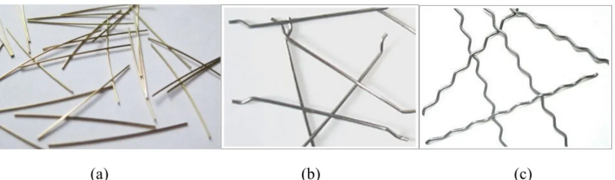
Different shapes and geometries of metallic fibers are commercially available. Their diameters vary between 0.10 and 1 mm. Steel fibers can be straight, end-hooked, crimped, and flattened-end as shown in Figure 2-2.
Figure 2-2: Various steel fibers shapes (Susetyo, 2009) 2.2.3.2 Synthetic fibers
Synthetic fiber such as polypropylene are non-corrosive, low cost, and lightweight fibers (Figure 2-3). Recently, the desire to use synthetic fibers as an additional reinforcement for concrete has grown significantly. Known for their resistance to alkaline conditions, synthetic fibers became an attractive substitute for steel fibers in concrete applications. In addition, they are chemically inert and have high melting point, which make them appropriate for structures subjected to aggressive environmental attacks. Synthetic fibers are usually categorized according to their modulus of elasticity (Carnovale, 2013 and Iyer, 2014). Synthetic fibers are very flexible, which prevent fibers from sticking or breaking during concrete pumping.
(a) Polypropylene fibers (b) Glass fibers
8
2.2.3.3 Natural fibers
Natural fibers, such as hair and jute, are the oldest types of fibers used in concrete applications. Compared to their fibers counterparts, they are considered less expensive and eco-friendly. With the implementation of new technologies, fibers can be extracted from new sources such as basalt rocks. Due to their high resistivity to alkalis and acids, basalt fibers became appropriate candidates for concrete applications.
Basalt fibers (Figure 2-4) are processed by melting crushed volcanic rocks. They are considered non-toxic and environmentally friendly (Iyer, 2014). Basalt-fiber reinforced concrete (BFRC) is commercially available and has been reported to have higher compressive strength, higher modulus of rupture, improved tensile properties, and higher flexural toughness than those of plain concrete (Iyer et al. 2014; Kizilkanat et al. 2015; Branston et al. 2016). In addition, BFRC exhibits higher modulus of elasticity, comparable tensile strength, and better alkaline resistance than the glass FRC (GFRC) (Ramakrishnan et al. 2003).
Chopped basalt fibers were reported to cause mixing problems due to their low density (Patnaik et al. 2015 and Jiang et al. 2014). To overcome this deficiency, a new fiber product, the MiniBarsTM, has been developed. MiniBarsTM has a density close to concrete (2.0 gm/cm3), which allows better concrete workability. MiniBarsTM are considered as a scaled-down version of the basalt fiber reinforcement polymer (BFRP) bars. According to a study conducted by Adhikari (2013), MiniBarsTM showed higher tensile strength and larger tensile rupture strain than the glass fibers. A literature review on the use of MiniBarsTM in construction applications is detailed in the following sections.
(a) (b)
9
2.2.4 Applications of fiber-reinforced concrete
As previously mentioned, the steel-fiber-reinforced concrete (SFRC) is the commonly-used type of FRC concrete. Owing to its improved flexural toughness, high impact and fatigue resistance, SFRC is commonly utilized in highway applications and pavement overlays. It is also used in warehouses, tunneling and mining, in which enhanced impact resistance is needed. SFRC is also found successful in precast components such as manhole covers, slabs, refractories, and non-pressurized pipes (Hannant, 1978).
Polypropylene fiber-reinforced concrete is generally used in non-structural applications due to its low impact resistance (Beaudoin, 1990). The typical applications are cladding, flat and corrugated cement sheets, cavity panels, tunnel lining materials, foundation and facing piles, under-water pipe, floating units, river walls, and thin shell concrete roofing material. Among the mostly-used polypropylene FRC is the glass-fiber-reinforced concrete (GFRC). The GFRC is commonly used in architectural applications such as cladding panels. This is attributed to its light-weight and economical cost in comparison to SFRC. GFRC became also an attractive solution for shell structures, prefabricated windows, pipes, channels, permanent formwork, floor slabs, and the rendering of masonry construction due to its ease of production in several complex shapes.
2.2.5 Factors affecting the properties of FRC 2.2.5.1 Fiber volume fraction
The amount of fibers added to a concrete mix is measured as a percentage of the total volume of concrete. This percentage is called the fiber volume fraction, Vf. Previous
studies showed that the fiber volume fraction is the most influencing parameter on the properties of FRC (Li, 2011). It has been shown that increasing Vf enhances the
compressive strength, the post-cracking behavior, and the ductility of the concrete element (Iyer et al. 2014). The increase in the fiber content increases the probability of intersecting the cracks and therefore boosts the ability of concrete to resist cracking (Barnston et al. 2016; Iyer et al. 2014). However, high fiber contents could lead to the loss of concrete workability during mixing and the segregation of its constituents (Jianxun Ma et al. 2012;). Problems associated with high fiber contents occur as a result of the
10
decreased paste volume fraction available for the free movements of fibers and aggregates (Patnaik et al. 2015).
Kakooei et al. (2012) investigated the properties of concrete mixes reinforced with polypropylene fibers. The concrete compressive strength, its permeability, and its electric resistivity were evaluated. The amounts of fibers added ranged between 0 and 2 kg per cubic meter of concrete. It was reported that concrete samples having 1.5 kg/m3 of polypropylene fibers showed better mechanical properties in comparison with other samples having less fiber dosages. The concrete compressive strength was found to be proportional to the amount of fibers added in the mix.
On the contrary, a study was conducted by Jianxun Ma et al. (2012) to examine the influence of basalt fiber content on the physical and mechanical properties of traditional cement-based materials. The volume fraction of fibers ranged between 1 to 3%. Test results showed that the fluidity of the concrete mix and the cubic compressive strength were inversely proportional to the added fiber content. In addition, it was proven that the toughness index was directly proportional to the fiber content up to 2%.
Kizilkanat et al (2015) studied the effect of fiber dosage of basalt and glass fibers on the mechanical properties of FRC. BFRC specimens showed the highest compressive strength at Vf = 0.50% whereas GFRC specimens showed the highest compressive
strength at Vf = 0.75%. Both mixes showed a reduction in their modulus of elasticity with
the increase of the fiber dosage. A 40% increase in the splitting tensile strength was observed in the BFRC mix at Vf = 1.0%. The increase in the flexure strength was more
pronounced in the BFRC mixes than in the GFRC ones and was directly proportional to the fiber dosage used. BFRC specimens showed flexural strengths of 13 and 34% higher than those of the plain concrete specimens at Vf = 0.5 and 1%, respectively. On the other
hand, GFRC specimens showed marginal increase in their flexural strengths with Vf =
0.5%. Fiber dosage of 0.25% had no effect on the fracture energy in both mixes. However, the fracture energy increased by 50% at Vf =1% in both mixes.
Adhikari (2013) tested the effect of different fiber volume fractions of basalt MiniBarsTM on the mechanical properties of concrete. Volume fractions of 2, 6, 8 and 10% were used. No loss of workability had been reported for any of the concrete mixes. It was found that the modulus of rupture of concrete increased with the increase of the
11
fiber content. In addition, the BFRC prisms showed higher ductility and better toughness than plain concrete prisms. Fiber content was reported to have no effect on the compressive strength of the tested concrete. However, the modes of failure of the concrete cylinders made of BFRC mixes became more ductile with the increasing of fiber content. BFRC cylinders with high fiber volume fractions were capable to sustain loading with larger deflections than those with low fiber content.
In a more recent study, Patnaik et al. (2015) tested the effect of MiniBarsTM dosages on the fresh and hardened concrete properties. The MiniBarsTM dosages ranged from 0.35 to 4% by volume. Physical inspection showed no segregation or balling of fibers during mixing. All concrete mixes showed acceptable slump with values ranging from 125 to 200 mm. The modulus of rupture was enhanced by increasing the fiber content. The highest enhancement in the modulus was obtained in the BFRC mix having 3% of fibers. A 25% increase in its modulus over plain concrete was recorded. Adding fibers prevented the brittle failure of the concrete cylinders proving the ability of MiniBarsTM to increase the energy absorption of concrete.
2.2.5.2 Fiber aspect ratio
The fiber aspect ratio is defined as the ratio of the fiber length to its diameter (1$/#$). Previous studies have demonstrated that the fiber aspect ratio affected the
properties of FRC mixes (Iyer et al. 2014). High aspect ratios enhance the bond between the fiber and the matrix (Mehta and Monteiro 2006; Banthia 2008). Shah and Rangan (1971) stated that the higher the aspect ratio the greater the ability of fibers to transmit stresses through cracks.
Iyer et al. (2014) evaluated the 28-day compressive strength and the modulus of rupture of BFRC beams. Specimens had different volume fractions and aspect ratios (same diameters but varying lengths). Plain concrete and steel-fiber reinforced (SFRC) specimens were cast as references. It was found that increasing the fiber length and the fiber amount considerably reduced the workability of concrete. The fiber length had an insignificant effect on the modulus of rupture or the compressive strength of concrete when low percentages of fibers were used. For high fiber percentages, the results showed an increase in the modulus of rupture with the increase of the fiber length. The study
12
showed that major improvements in the compressive strength could be achieved by using 36 mm basalt fibers with Vf = 0.31% but not as high as that of SFRC specimens.
2.2.5.3 Fiber geometry
Commercially-available fibers have different shapes namely, straight, end-hooked, crimped, and flattened-end as shown in Figure 2-5. Susetyo (2009) conducted an experimental study that showed that concrete matrices reinforced with short fibers have higher ductility and better crack control than those reinforced with long fibers. This was attributed to the large amounts of short fibres that could exist within the matrix, which improves the concrete ability to control and bridge the developed cracks.
(a) (b) (c)
Figure 2-5: Commercially available steel fibers: (a) Hooked fibers, (b) Straight fibers, and (c) Crimped fibers (adapted from steelfiber.org)
A study by Branston et al. (2016) investigated the mechanical properties of two types of basalt fibers (chopped basalt fibers and MiniBarsTM). It was observed that adding chopped basalt fibers retarded the first crack but had no effect on the compressive strength or the post cracking behavior. Further examination using scanning electronic microscope showed that specimens containing chopped basalt fiber failed due to rupture of the fibers while those containing MiniBarsTM fibers failed due to fibers’ pullout.
2.2.6 Constitutive models of fiber-reinforced concrete
The utmost goal of the constitutive models of FRC is to model the post-peak tensile response of the concrete mix. This is attributed to the fact that most FRC mixes are anticipated to resist the tensile stresses that might be applied to concrete. Two approaches are commonly used to achieve this goal. The first approach considers the fibers as an additional reinforcement to concrete, which provides the concrete with additional tension stiffening when subjected to tensile stresses. The parameters that
13
govern these models include the fiber aspect ratio, the fiber volume content, and the fiber bond strength to concrete. This approach is considered effective and provides direct evaluation of the tensile response of the FRC mix under study. The alternative model uses the concepts of fracture mechanics to acquire the post-peak tensile response of concrete. This approach requires carrying out an inverse analysis using the measured response obtained from fracture tests such as wedge splitting tests (Lofgren et al., 2005). This approach has limited applicability as it requires set of tests to obtain the fracture parameters. A brief summary of some of the currently available models in the literature is presented in the following sections.
2.2.6.1 Marti et al. (1999) Model
This model is based on the investigation that has been carried out by Aveston and Kelly (1973), in which it has been reported that the effective fiber volume fraction across the crack is half of the total volume fraction of the fibers used. However, member dimensions, which might have considerable effect on the distribution of the fibers, were not considered. Besides, the size of the specimens used for model verification were relatively small in comparison with the fiber length (Lee et al., 2011). Marti et al. (2009) reported that the number of fibers that would be considered bonded to the matrix decreased linearly as the crack width increases. Thus, the relationship between the tension stress applied on the fiber and the crack width could be represented by a decaying parabolic function, (1- 2w ⁄ lf). This relationship has been frequently utilized in other FRC
models such as that of Voo and Foster (2003).
2.2.6.2 Variable Engagement Model (VEM) (2004)
This model was firstly presented by Voo and Foster in (2004). It was originally developed to consider the effect of randomly distributed fibers on the post-cracking behavior of SFRC mixes while ignoring the orientation of the fibers in the matrix. The VEM is formed by the superposition of two components namely (a) the tension softening of the concrete matrix without fibers and (b) the contribution of fibers in tension after cracking. The superposition of the two components describes the behavior of the FRC. This model will be discussed in detail in Chapter 5 of the current work.
To model the effect of fibers on the tensile behavior of FRC mixes, the model introduces two assumptions that have been used in further model development. The first
14
assumption is that the embedded fiber is presumed to be only pulled out from the side of the crack with the shorter embedded length while the longer embedded end of the fiber remains rigid. As will be discussed further in Chapter 5, this assumption allows for a much easier solution process. The other assumption is that the axial elastic deformation of the fibers was ignored. Sujivorakul et al. (2000) have proven that this assumption had a slight effect on the overall response of the fibers within the mix. The VEM model also introduces the concept of fiber engagement, which states that the tensile contribution of the fibers is delayed until a certain slip occurs between the fiber and the matrix. This phenomenon results in better energy absorption. This concept is evident from the softening curves of the post-peak of the uniaxial direct tensile test in which the decay curve for plain concrete is steep whereas the decay for FRC is soft due to the energy absorption associated with the presence of fibers. This concept is illustrated in details in Chapter 5.
2.2.6.3 Stroeven (2009) Model
Stroeven (2009) developed a new model to solve the problem of the orientation of fibers in the matrix while taking into consideration the effect of compaction procedures on the fiber alignment within the structural element. The model employs a statistical probability approach to estimate the number of fibers crossing a crack in the element. In addition, it utilizes a probabilistic distribution function to determine the inclination angle of the fibers according to spatial constrains. The previously mentioned parameters are summed up in an efficiency factor for fiber tensile capacity. This concept was employed in the development of future models such as that of Lee et al. (2011a).
2.2.6.4 Diverse Embedment Model (DEM) (2011)
The Diverse Embedment Model (DEM) is the most recent constitutive model for the behavior of the FRC in tension. The model is derived by (Lee et al., 2011a; Lee et al., 2011b) with consideration being given to all possible fiber orientations and embedment lengths, which requires a fiber orientation factor, αf, to be introduced. Unlike the VEM,
DEM considers the crack width to be the sum of the slip exhibited in both the short and long ends of the fiber that crosses a crack (Lee et al., 2011a). This assumption makes the model quite complicated since it requires an iterative double numerical integration to be performed to predict the stresses in the fibers at a given crack width. This complex
15
approach limits the implementation of the model in finite element software and design codes (Lee et al., 2013).
2.2.6.5 Simplified Diverse Embedment Model (SDEM)
The simplified diverse embedment model was introduced by Lee et al. (2013) to simplify the DEM model. Alike the VEM, the SDEM assumes that the fiber slippage occurs on the shorter embedded side only while ignoring the slip that might occur on the longer embedded side. As a result, the need for double numerical integration is eliminated and a direct relationship for the fiber contribution in tension is derived without significant loss in accuracy (Lee et al., 2013). The proposed equations are as follows:
For straight fibers:
fst = αf Vf Kst τ .' -' (1- 4567 .' ) 2 Eq.5-7
For hooked fibers:
feh = αf Vf Keh τ( 4(.9:45- 67
' )
2 Eq.5-8
where:
Vf is for fiber volumetric ratio; lf is the fiber length; df is the fiber diameter; ;<= is the
crack width; αf is the fiber orientation factor that can be assumed to be 0.5 for cases where
the dimensions of the structural member are much larger than the fiber length (Lee et al., 2013); τ is the pullout strength of a single fiber; li is the length of the straight part of the
fiber between the mechanical anchorages for end-hooked fibers; and Kst and Keh are
material parameters that consider the effect of fiber inclination angle on the frictional bond behavior.
2.3 Basalt fiber-reinforced polymer (BFRP) bars
This section reports on the use of continuous fiber-reinforced polymer (FRP) bars in reinforcing concrete elements. Due to the wide range of FRP types, this section will focus on the recently developed basalt FRP (BFRP) bars and their use as reinforcement in concrete sections.
BFRPs are the newest members in the FRP family. BFRP bars consist of basalt fibers impregnated in polymeric resin. The fibers are extracted from natural basalt rocks
16
through a melting process. They are known for their high tensile strength, high modulus, and large strain to failure. Furthermore, they are known for their better durability and chemical stability over their GFRP counterparts, which make them adequate for use in alkaline environments. The literature presented below is divided to three main sections as follows:
- A review on the properties and durability of BFRP bars,
- A review on the use of BFRP bars as reinforcement for concrete elements cast with plain concrete, and
- A review on the use of BFRP bars as reinforcement for concrete elements cast with FRC.
2.3.1 Properties and durability of BFRP bars
El Refai et al. (2015) investigated the bond performance of BFRP bars to concrete through direct pullout tests. Cylinders reinforced with GFRP bars were cast for comparison. Different diameters of BFRP and GFRP bars, with variable embedment lengths in concrete, were used in this study. Test results proved that BFRP bars could be a proper alternative to GFRP bars as they attained 75% of the bond strength of GFRP bars. Smaller diameters of BFRP bars showed more adhesion to concrete than the large bars. This adhesion led to better bond between the BFRP bars and the surrounding concrete. It was noticed that BFRP and GFRP bars had similar trend regarding the effect of embedment length on the bond stress: the bond strength of both bars was inversely proportional to the embedment length.
Altalmas et al. (2015) studied the effect of various environmental conditions on the bond strength of pullout concrete cubes reinforced with sand-coated BFRP bars. Acid, saline, and alkaline solutions were used to simulate different harsh environmental conditions. The program consisted of 62 cube specimens reinforced with either BFRP or GFRP bars. Specimens were either unconditioned or subjected to environmental conditions for 30, 50, and 90 days. Results showed that BFRP specimens had better bond strength with concrete over the ribbed GFRP specimens. Regardless of the exposure condition, BFRP specimens subjected to saline and alkaline solutions showed a 25% bond reduction after 90 days while 14% reduction was reported for those immersed in acidic solution for the same duration of exposure. GFRP specimens showed 25 and 17% bond reduction after 90 days exposure in acidic and alkaline (and saline) conditions, respectively.
17
Elgabbas et al. (2015) investigated the short- and long-term properties of three different types of BFRP bars. The bars were conditioned in alkaline solutions simulating the concrete environment to assess their ability as internal reinforcement for concrete elements. The physical and mechanical properties of the bars were determined according to ACI-440.1R-15 and CSA-S807-10 test procedures. Concerning the short-term properties, the results showed that BFRP bars met the physical and mechanical requirements stated by both ACI and CSA and could be placed in the same category as grade II and grade III GFRP bars. However, specimens submerged in the alkali solution showed significant degradation. Scanning electronic microscopy (SEM) confirmed that this degradation was attributed to the poor bonding between the resin and the fibers.
Hassan et al. (2016) studied the bond durability of BFRP bars embedded in concrete and subjected to aggressive environments. A total of 50 BFRP specimens were immersed in alkaline solution at three different temperatures (40, 50, and 60o C) for 1.5, 3, and 6 months. Five unconditioned specimens were tested at room temperature 28 days after casting for comparison. The bond strength generally decreased with the increase in the surrounding temperature. Exposure for 1.5 months increased the bond strengths by 25 and 26% of the specimens conditioned at 50 and 60oC, respectively, whereas a minor reduction in the bond strength (about 4%) was recorded for specimens conditioned at 40oC. Specimens conditioned for 6 months at 40oC had the maximal bond loss (about 16%). However, all specimens met the minimum bond strength reported by ACI-440.6-08 and CSA-S807-10. Depending on the environmental conditions, the bond-strength retention of BFRP bars after 50 years of service was predicted between 71 and 92%.
2.3.2 BFRP-reinforced elements
Mahroug et al. (2013) studied the flexural response of simple and continuous slabs reinforced with BFRP bars. A total of 6 slabs having different reinforcement ratios and bars arrangement were tested in flexure. One continuously-supported slab reinforced with steel bars was also tested as reference. Test results showed that the BFRP-reinforced slabs had higher deflections and deeper cracks than the reference slab. Over-reinforced BFRP-reinforced slabs showed high loading carrying capacity. The authors reported that ACI-440.1R-06 provisions overestimated the flexural capacity in most of BFRP-reinforced concrete slabs. ISIS-M03-07 and CSA-S806-06 reasonably predicted the deflections of the BFRP-reinforced slabs whereas ACI-440.1R-06 underestimated their deflections.
18
Lapko and Urbański (2014) conducted an experimental and theoretical analysis on concrete beams reinforced with BFRP bars. The research consisted of three beams reinforced with BFRP bars and three reference beams reinforced with conventional steel bars. The results showed that the BFRP-reinforced beams showed higher deflections and crack widths in comparison with their steel-reinforced counterparts. CSA-S806-02 accurately predicted the beam deflections at the initial loading level (up to 20% of the load) with 9% discrepancy between the theoretical and experimental deflections. As the load increased, CSA-S806-02 showed large discrepancy between the predicted and the experimental deflections (up to 49%). Deflections based on ISIS-M03-07 provisions and by the modified equation of Bischoff were the most accurate throughout all phases of loading.
Pawłowskia and Szumigałaa (2015) investigated the flexural behavior of full-scale BFRP-reinforced beams. Three beams with different reinforcement ratios were tested until failure. Results showed that BFRP-reinforced beams having high reinforcement ratios experienced higher ultimate loads and stiffness that those having low reinforcement ratios. However, the former beams showed less ductility than the later ones. It was proven that the flexural design of BFRP-reinforced members is governed by the serviceability limits since the measured deflections at ultimate were six times greater than the permissible values. Numerical analysis using ABAQUS showed a good agreement with the experimental results.
Zhang et al. (2015) studied the deflections of concrete beams reinforced with BFRP bars. Six beams reinforced with different ratios in addition to one steel-reinforced control beam were tested under four-point loading. Test results showed that BFRP-reinforced beams exhibited brittle failure especially the under-BFRP-reinforced ones. ACI-440.1R-06 accurately predicted the flexure capacities of the beams but underestimated their deflection capacities. A modified equation considering the influence of the increased compressive zone was proposed. This equation showed higher accuracy in predicting the deflections of the BFRP-reinforced beams than the ACI equation. A finite element model using ABAQUS was used to model the BFRP-reinforced beams and showed good agreement with the experimental results.
Tomlinson and Fam (2015) evaluated the flexural and shear performances of concrete beams reinforced with BFRP bars and stirrups. Nine specimens were reinforced
19
with BFRP bars and tested under four-point loading. Steel-reinforced specimens were tested for comparison. The parameters investigated included the type of stirrups (steel or BFRP) and the reinforcement ratio (varying from 0.28 to 1.60). Results showed that the service and ultimate loads of BFRP-reinforced specimens were directly proportional to the flexural reinforcement ratio regardless of the shear reinforcement type. In addition, BFRP-reinforced beams showed significantly higher strengths (2.8 times) than those of their steel-reinforced counterparts having the same reinforcement ratio. ACI-440.1R-06 and CSA-S806-12 adequately predicted the flexural strength of the BFRP-reinforced beams.
Ge et al. (2015) studied the flexural behavior of hybrid concrete beams reinforced with BFRP and steel bars. Three hybrid concrete beams reinforced with BFRP bars and steel bars, one concrete beam reinforced with BFRP bars only, and one concrete beam reinforced with steel bars were cast. Test results showed that the ratio between the area of FRP bars to that of steel bars (A?
A@) governed the deflection and crack spacing in the hybrid beams, as both decreased with the increase of this ratio. It was observed that under the same loading, the deflection and crack spacing were larger in the BFRP-reinforced beams than in the steel-reinforced ones. Hybrid beams showed deflections less than those encountered in the BFRP-reinforced beams but higher than those observed in the steel-reinforced ones.
El Refai et al. (2015) studied the flexural performance of hybrid reinforced concrete beams. The study included six beams reinforced with a combination of steel and GFRP bars and three beams reinforced with only GFRP bars. Results showed that beams with hybrid reinforcements had a better structural behavior over GFRP reinforced beams in terms of load-carrying capacity, ductility, deformation and cracking. The authors proposed a new bond coefficient, kb, which takes into consideration the GFRP bar
diameter and the ratio of GFRP to steel bars. By applying this coefficient to ACI-440.1R-06 equation, better crack width estimation using was observed.
In a recent study, Elgabbas et al. (2016) investigated the structure performance of six concrete beams reinforced with BFRP bars. The beams had different reinforcement ratios, number of reinforcement layers, and bar sizes. It was found that the ACI-440.1R-15 and CSA-S806-12) overestimated the cracking moment by an average of 27 and 24%,
20
respectively. The average bond-dependent coefficient, kb, was estimated as 0.8, which
was in agreement with the recommendation of the Canadian Highway Bridge Design Code (CSA-S6-14). The obtained results confirmed that the pre-cracking response of all beams was similar until cracking occurred with no evidence of being affected by the reinforcement ratio. However, after cracking, it was reported that beams with higher reinforcement ratios had better crack distribution and less crack widths. The authors concluded that CSA-S806-12 provisions provided reasonable deflections yet conservative values over the ACI values for beams reinforced with BFRP bars.
2.3.3 Hybrid FRC/FRP specimens
Won et al. (2010) examined the cracking behavior of 16 FRP-reinforced concrete beams. Parameters used in this study were the bar type (GFRP, CFRP, or steel) and the reinforcement ratio. Polypropylene fibers were added to the concrete mix at 1% by volume. Test results showed that adding polypropylene fibers enhanced the cracking response of concrete. However, it reduced its compressive strength by 23% in comparison with that of plain concrete. Both GFRP and CFRP under-reinforced beams had small number of cracks while the over-reinforced ones had a large number of cracks that were formed as the loading increased. Polypropylene fibers had insignificant effect on the performance of the steel-reinforced specimens.
Belarbi et al. (2011) investigated the effect of environmental exposure on the bond behavior of FRP-reinforced concrete elements. A total of 36 specimens reinforced with FRP bars were subjected to combined freeze-and-thaw cycles and high temperature while being submerged in saline solution. Plain concrete specimens were subjected to the same environmental conditions for comparison. It was found that 0.5% of polypropylene fibers significantly enhanced the bond durability of the FRP bars to concrete. An average of 28% reduction in bond strength was observed for FRP bars in plain concrete whereas only 6% reduction was observed in FRC specimens.
Wang and Belarbi (2013) investigated the long-term flexural performance of FRP-reinforced concrete beams. Beams cast with plain concrete served as controls. Twenty-six over-reinforced concrete beams were subjected to freeze-and-thaw cycles followed by high temperature cycles before being tested in flexure. It was reported that all specimens failed due to concrete crushing. Test results showed that conditioning had slight effect on
21
the flexural capacities of both plain and FRC beams. However, 0.5% of polypropylene fibers enhanced the ductility index of both conditioned and unconditioned specimens by an average of 30%.
Wang and Belrabi (2015) conducted a research to investigate the possibility of using steel-free system to overcome corrosion problems. Their systems consisted of hybrid CFRP/GFRP bars and 0.5% randomly distributed polypropylene fibers. A total of 12 over-reinforced specimens were subjected to four-point loading configuration. The investigated parameters included the size and type of FRP bars and the concrete mix (FRC and plain mixes). All plain concrete specimens failed by concrete crushing. However, FRC beams failed in a more ductile behavior that was attributed to the bridging effect of the added fibers. Results showed that the fibers had enhanced the concrete ultimate strain to an average of 3300 micro-strains compared to 2950 micro-strains measured in plain concrete. The addition of fibers improved the flexural capacity of the FRC-reinforced beams up to 9% and their ultimate deflection up to 27%.
High et al. (2015) conducted an experimental program to investigate the use of BFRP bars as flexural reinforcement for concrete members. In addition, they studied the effect of using chopped basalt fibers as an additive to enhance the mechanical properties of concrete. Six one-way slabs reinforced with BFRP bars were tested in flexure and their results were compared with those predicted by ACI-440.1R-06 (2006). Under-reinforced slabs showed a lower carrying capacity than the balanced and over-reinforced slabs due to the rupture of BFRP bars in the former slabs at ultimate. It was proven that ACI-440.1R-06 provisions adequately predicted the flexure capacities of the slabs but significantly underestimated the deflections at service loads. Accurate deflections were predicted by using the equation proposed by Bischoff and Gross (2011). The use of chopped basalt fibers resulted in an increase in the modulus of rupture of concrete with a slight effect on its compressive strength.
2.4 Concluding remarks from the literature review
A summary of the previous studies that have been carried out on the flexural response of concrete elements reinforced with FRP, FRC, or hybrid (FRC/FRP) has been presented. Parameters recognized to have a significant effect on the behaviour of these elements are identified. From this review, the following points can be concluded:
22
• The presence of fibers in concrete has a significant influence on the behavior of concrete elements. They have been successfully known by their ability to control cracks and shrinkage and to enhance the post-cracking behavior. Those enhancements occur as a result of the bridge action maintained by the fibers. • Fiber volume fraction is the most influencing parameter on the properties of FRC
mixes. Sufficient fibers are required to enhance the bridging action while excessive fibers could lead to workability and segregation problems.
• Synthetic fibers are considered promising candidates for reinforcing concrete structures. Owing to their alkaline resistivity, high melting point, high tensile strength, and non-corrosive nature, they are seen as promising alternatives to steel fibers.
• The aspect ratio of the fiber is another important factor that influences the behavior of FRC especially its compressive strength and toughness.
• In FRP-reinforcement elements, the reinforcement ratio is a significant parameter that affect the flexural performance. Specimens having high reinforcement ratios experienced higher ultimate loads and stiffness.
• ACI-440.1R-06 and CSA-S806-06 formulations are accurate in predicting the flexure capacities of BFRP-reinforced elements. However, they don’t accurately estimate their deflection capacities.
• There is a noticeable lack of studies on the flexural response of BFRP slabs cast with BFRC mixes. Among the few studies found in the literature, this hybrid system proved to be efficient in enhancing the compressive strength of concrete and improving the overall durability.
• None of the previous studies has investigated the effect of different fiber volume ratios of basalt fibers on the behavior of concrete elements reinforced with BFRP bars.
• None of the previous studies has developed a numerical model that is capable to simulate the flexural response of BFRP-reinforced concrete elements cast with different volume fractions of basalt fibers.
23 2.5 Research objectives
The main objective of the current study is to investigate the flexural response of BFRP-reinforced slabs cast with FRC mixes having different ratios of the newly developed basalt fibers (MiniBarsTM). The detailed objectives of the current study are as
follow:
• To investigate the effect of different volume fractions of basalt MiniBarsTM on the
mechanical properties of concrete.
• To investigate the flexural response of BFRP-reinforced slabs cast with FRC having different dosages of MiniBarsTM.
• To develop a numerical model that is able to predict the response of BFRP/FRC-reinforced slabs.
24
Chapter 3: Experimental Program
3.1 Scope
In this chapter, the details of the experimental program are presented. The description of the test specimen, the fabrication process, the material properties, the test setup, and the test procedure are provided.
3.2 Test program and investigated parameters
The experimental program included eight BFRP-reinforced slabs tested under four-point loading configuration that were fabricated and tested in the Structures laboratory of Qatar University. The test matrix is shown in Table 3-1. The main variables were the fiber volume fraction, A$, and the longitudinal BFRP reinforcement ratio used,
B. The slabs were divided into two groups: group A with a reinforcement ratio (B BC = 1.39) and group B with a reinforcement ratio of 2.8, where BCI. is the balanced
reinforcement ratio of the BFRP-reinforced slab section. Slabs of group A represented typical over-reinforced slabs having reinforced ratios approximately equal to 1.4 times the balanced reinforcement ratio as recommended by ACI-440.1R-15 whereas slabs of group B were conservatively over-reinforced with a reinforcement ratio that was double that of slabs of group A. The balanced reinforcement ratio, which refers to a simultaneous rupture of FRP bars and concrete crushing, was calculated from the force equilibrium and strain compatibility assumptions as follows:
BC = 0.85MN $6 O $'P Q'R6P Q'R6PS$'P Eq. 3-1 where:
β1 = ratio of depth of equivalent rectangular stress block to depth of the neutral axis; T<U =
concrete compressive strength; T$ = ultimate strength of the BFRP bar; V$ = modulus of elasticity of the BFRP bar; and W<X= maximum concrete compressive strain (0.0035 for CSA-A23.3-04 provisions).
Three fiber volume fractions (0.5, 1, and 2%) were used to cast the slabs. For each group, one BFRP-reinforced slab cast with plain concrete acted as control. As shown in Figure 3-2, slabs of group A were internally-reinforced with 2-10 mm and 2-12 mm
25
diameter BFRP bars, which corresponded to a reinforcement ratio of 1.39 BCI.. Three of the slabs of group A were cast with basalt fiber-reinforced concrete (BFRC) with different A$ that ranged between 0.5 to 1% whereas the fourth specimen was cast with plain concrete. Slabs of group B were reinforced with 4-10 mm and 4-12 mm BFRP bars, which corresponded to a reinforcement ratio of 2.8 BCI.. Similar to group A, three slabs were cast with three different A$ while one slab was cast with plain concrete.
The slabs were labeled as follows: the first digit refers to the slab group (1 or 2) while the last digits refer to the volume fraction of the fibers added. For instance, slab R1-2.0 refers to a slab in group A that was cast with FRC mix having A$ = 2%. All slabs
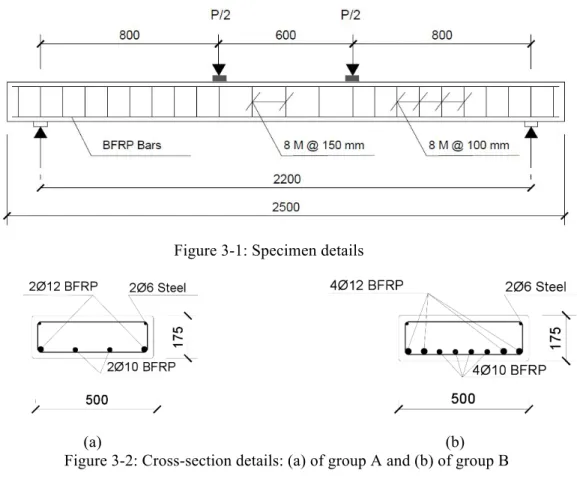
were 175 mm deep, 500 mm wide, and 2500 mm long with a clear cover of 25 mm at each side, which creates a reinforcement depth of 144.5 mm. Figure 3-1 and Figure 3-2 show the details of the slab dimensions and reinforcement. The slabs were reinforced at the bottom with BFRP bars of different diameters according to their reinforcement ratio. All of the tested slabs were reinforced with 8 mm diameter double-leg steel stirrups that were spaced at 100 mm in the shear span and 150 mm in the moment zone. At the top, two 6 mm diameter steel bars were installed to act as hangers for the stirrups.
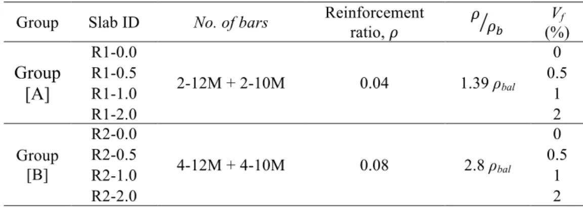
Table 3-1: Test matrix
Group Slab ID No. of bars Reinforcement ratio, B B BC Vf
(%) Group [A] R1-0.0 2-12M + 2-10M 0.04 1.39 ρbal 0 R1-0.5 0.5 R1-1.0 1 R1-2.0 2 Group [B] R2-0.0 4-12M + 4-10M 0.08 2.8 ρbal 0 R2-0.5 0.5 R2-1.0 1 R2-2.0 2
26 Figure 3-1: Specimen details
(a) (b) Figure 3-2: Cross-section details: (a) of group A and (b) of group B 3.3 Material properties
3.3.1 Concrete
Eight batches of concrete were supplied by a local concrete plant. The concrete mix design is given inTable 3-2.Three standard cylinders (150 mm in diameter and 300 mm in height) and three standard prisms (150 x 150 x 300 mm) were cast from each concrete batch. The cylinders were used to determine the 28-day compressive strength while the prisms were used to evaluate the modulus of rupture (MOR) of concrete. The cylinders and prisms were subjected to the same curing conditions as those of the slabs.
Table 3-2: Concrete mix design Concrete constituent Quantity (Kg/mZ) Cement 367 Water 180 Water/Cement 0.49 Fine aggregates 730 Coarse aggregates 1080
27 3.3.2 BFRP bars
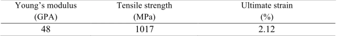
As previously mentioned, BFRP bars of nominal diameters 10 and 12 mm were used to reinforce the slabs. The surface of the BFRP bar was sand-coated as shown in Figure 3-3. The mechanical properties of the BFRP bars were determined in a previous study conducted by El Refai et al. (2015) and are listed in Table 3-3.
Figure 3-3: BFRP bars
Table 3-3: Mechanical properties of BFRP bars (El Refai et al. 2015) Young’s modulus (GPA) Tensile strength (MPa) Ultimate strain (%) 48 1017 2.12 3.3.3 Steel reinforcement
Two 6 mm diameter steel bars were used in the compression zone of each slab to act as stirrups hangers. The stirrups in all slabs were 8 mm in diameter. Coupons were taken from the steel bars and tested under uniaxial tension to determine their mechanical properties. The tensile test results are given in Table 3-4.
Table 3-4: Mechanical properties of steel reinforcement
Bar size Sample # fy fu fy, avg
(MPa) fu, avg (MPa) (MPa) (MPa) No. 6 1 535 605 560 620 2 579 635 3 565 618 No. 8 1 565 635 577 648 2 584 653 3 583 657
28 3.3.4 Basalt fiber-reinforced concrete (BFRC)
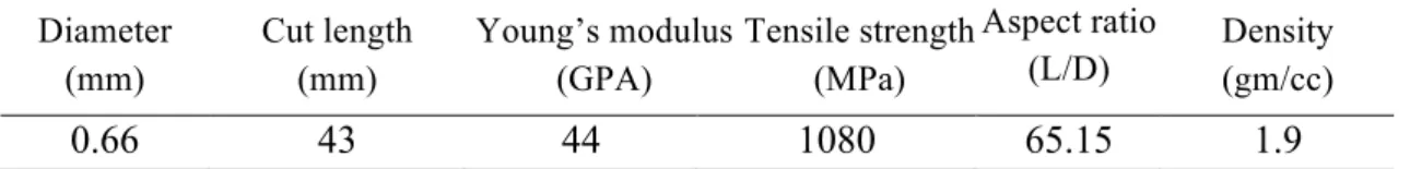
MiniBarsTM is the commercial label of the basalt macro fibers used in this study
(Figure 3-4). The mechanical properties of the MiniBarsTM as reported by the
manufacturer are listed in Table 3-5.
Figure 3-4: Basalt MiniBarsTM
Table 3-5: Mechanical properties of MiniBarsTM
Diameter (mm) Cut length (mm) Young’s modulus (GPA) Tensile strength (MPa) Aspect ratio (L/D) Density (gm/cc) 0.66 43 44 1080 65.15 1.9
3.4 Slab instrumentation and fabrication
Prior to concrete casting, the BFRP bars were instrumented with strain gauges at midspan. First, the surface of the bars was grounded using an electric grinder. The strain gauges were then bonded to the bar using a chemical adhesive. Finally, an insulation cover was installed on the top of the gauges to protect them during concrete casting. This procedure is shown in Figure 3-5.
29
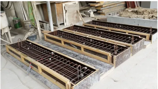
The cages were then assembled and placed in wooden forms prior to casting as shown in Figure 3-6. Plastic chairs of 25 mm height were placed in the forms to ensure a uniform clear concrete cover all over the sides of the slabs.
Figure 3-6: Slab cages installed in the wooden forms
Plain and fiber concrete mixes were supplied by a local contractor. For the BFRC mixes, the fibers were added during the mixing process as recommended by the manufacturer to ensure the homogeneity of the mix. At the end of casting, the surface of the slabs was finished manually. The specimens were then covered using wet burlaps and left for curing for 28 days. Figure 3-7 summarizes the casting and curing process.
30
Figure 3-7: Concrete casting and curing
3.5 Test setup
The test setup is shown in Figure 3-8. All slabs were tested in flexure under four-point load configuration with a clear span of 2200 mm. The load was applied using a hydraulic jack in a self-reaction Instron frame, as shown in Figure 3-8, at two locations spaced 600 mm (refer to Figure 3-2). Two linear variable differential transducers (LVDT) were placed at the north and south sides of the slabs at midspan to measure the midspan deflections during loading. Concrete strains were measured with two strain gauges that were installed at midspan on the top surface of concrete. The load was applied in displacement control at a rate of 2 mm/min. Data from strain gauges and LVDTs were recorded using a 30-channel data acquisition system at a rate of 5 readings/s.
31
Chapter 4: Experimental Results
4.1 Introduction
This chapter presents and discusses the test results. The chapter begins with a presentation of the results of the material’s characterization tests followed by the results of the four-point bending tests that were conducted on the BFRP-reinforced slabs. Comparisons between different slabs in terms of flexural response, load-carrying capacities, deflections, and failure modes are presented and discussed.
4.2 Material test results
The effect of basalt fibers on the physical properties of concrete is presented in this section. As previously mentioned in Chapter 3, standard concrete cylinders (150 x 300 mm) were tested to determine the compressive strength of the concrete used while standard prisms (150 x 150 x 600 mm) were used to determine the modulus of rupture (MOR) of concrete. Both cylinders and prisms were subjected to the same curing conditions as those of the BFRP-reinforced slabs. Then, the cylinders and prisms were kept under room temperature before being tested on the same day of the slab tests. For each test, the influence of different volume fractions, Vf, of fibers is emphasized.
Compressive strength and maximum cracking stress for each concrete batch are shown in Table 4-1 and Table 4-2, respectively.
4.2.1 Compression tests
The compression tests were conducted according to ASTM-C469 provisions (2014). Different concrete mixes were used as previously shown in Table 3-2 in Chapter 3. For each concrete batch, three cylinders were cast and cured for 28 days. Then, the top surface of the cylinders was grounded before being tested. Table 4-1 shows the average compression strength for each batch of concrete.
32 Table 4-1: Compressive strength results
Sample f
’ c MPa
Average
MPa Standard deviation
COV (%) Group A Vf = 0% 33.28 0.74 2.22 1 33.28 2 32.16 3 31.89 Vf = 0.5% 35.64 0.9 2.54 1 33.84 2 35.64 3 34.58 * Vf = 1% 30.64 0.69 2.24 1 30.67 2 31.76 3 30.49 Vf = 2% 42.62 0.94 2.20 1 42.78 2 42.56 3 41.06 Group B Vf = 0% 38.05 2.07 5.44 1 36.12 2 37.80 3 40.24 Vf = 0.5% 36.75 1.19 3.14 1 35.30 2 36.71 3 37.44 Vf = 1% 39.16 0.70 1.78 1 38.54 2 39.92 3 39.03 Vf = 2% 42.52 0.77 1.83 1 42.76 2 43.15 3 41.65
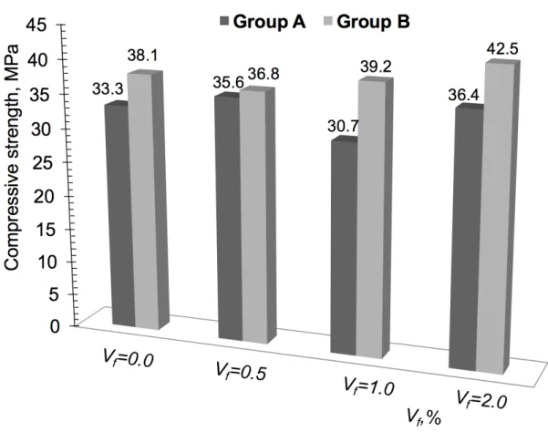
33 Figure 4-1: Average compressive strengths of different concrete mixes used in this study
Figure 4-1 shows the relationship between the volume fraction of the added fibers and the concrete compressive strengths as obtained from the compression tests. It can be observed that plain concrete mixes (Vf = 0%) yielded compressive strengths, f’c, that were
close to the target strength (35 MPa). The test results indicated that basalt fibers slightly enhanced the compressive strength of concrete: concrete cylinders with Vf = 0.5% showed
an increase in the compressive strength of 7%. Concrete mixes with Vf = 2% had the
highest average compressive strength = 42.5 MPa, which represented 22% more than that of the plain concrete and about 15 and 21% increase over the compressive strengths of concrete mixes with Vf = 0.5% and 1%, respectively. The only exception was the concrete
mix with Vf = 1% used to cast the slabs of group A. A decrease of 7% in the concrete
compressive strength was observed. This was attributed to an error in the concrete mix design before casting. It is important to note that due to this error, the results of slab R1-1.0 of group A cast with Vf = 1% were excluded from the test analysis. On the other hand,
cylinders with Vf = 2% used to cast the slabs of group B showed an increase of 12% in
their compressive strength over that of plain concrete specimens and an increase of 6% over those with Vf = 0.5%.