I
Université de Montréal
Cyclonickellation des phosphinites dérivées de phénols et naphtols
Régiosélectivité, Mécanisme, Fonctionnalisation et Formation de nouveaux Pinceurs
Par
Loïc P. Mangin
Département de chimie, Faculté des arts et des sciences
Thèse présentée en vue de l’obtention du grade de Philosophiæ Doctor en chimie
Décembre 2019
II
Université de Montréal
Département de chimie, Faculté des arts et des sciences
Cette thèse intitulée
Cyclonickellation des phosphinites dérivées de phénols et naphtols
Régiosélectivité, Mécanisme, Fonctionnalisation et Formation de nouveaux Pinceurs
Présentée par
Loïc P. Mangin
A été évaluée par un jury composé des personnes suivantes
Frank Schaper Président-rapporteur Davit Zargarian Directeur de recherche Christian Reber Membre du jury Samuel A. Johnson Examinateur externe
III
Résumé
Cette thèse présente différents aspects de la cyclonickellation des phosphinites de type Aryl-OP(i-Pr)2, leur potentiel dans la fonctionnalisation et leur utilité pour former des nouveaux
types de complexes de types pincer de nickel. Le Chapitre 1 constitue une introduction générale sur l’importance de la liaison carbone-nickel en chimie organométallique. Diverses stratégies de formation des liens C-Ni dans des composés classiques (monodentés), des composés de types pincer (tridentés) et des composé cyclonickellés (bidentés et tridentés) y sont présentées, incluant des réactions impliquant des précurseurs de Ni0, de NiII ou de NiIV. Ce chapitre présente également
la réactivité de ces composés comportant des liens C-Ni, et met l’emphase sur la réactivité des liaisons carbone-nickel, en particulier dans les processus catalytiques destinés à la fonctionnalisation des liens C-H, en utilisant des groupes directeurs. Les phosphinites sont ensuite présentées comme des groupes directeurs intéressants en catalyse, bien qu’elles aient surtout été utilisé avec d’autres métaux que le nickel. La dernière partie de ce chapitre pose les questions qui tenterons de trouver réponse dans les travaux présentés aux chapitres suivants.
Les Chapitres 2 et 4, basés sur des articles publiés, présentent l’isolation et la caractérisation de composés dimériques de type [{κP,κC-(i-Pr)
2POAr}Ni(μ-Br)]2 issus de
l’ortho-nickellation des phosphinites dérivées des phénols et des naphtols substitués, ainsi que de certains de leurs adduits monomériques d’acétonitrile ou du ligand lui-même. Ces discussions cherchent à répondre à la question de régiosélectivité de la cyclonickellation : on y démontre que cette réaction est gouvernée par les facteurs stériques, menant à la métallation préférablement (pour les substituants fluor) ou exclusivement (pour les substituants plus volumineux) aux carbones les moins encombrés, lorsque deux positions ortho sont disponibles, et que la réaction mène toujours à la formation de nickellacycles à 5 chainons. Ainsi, les phénols C3-substitués subissent la métallation au carbone C6, alors que les 1- et 2-naphtols subissent la nickellation aux positions C2 et C3, respectivement.
Ces deux chapitres démontrent que la métallation peut avoir lieu sur des carbones qui possèdent déjà un voisin encombrant (F, OMe, benzo), menant à des structures relativement distordues, mais que la nickellation n’est pas produite dans les conditions standard au voisinage des substituants Me et Cl qui sont plus volumineux, ni au carbone C8 du 1-naphtol qui mènerait à
IV
un nickellacycle à 6 chainons. L’étude structurale permet de rationaliser les régiosélectivités observées, et les études par diverses méthodes RMN complètent la caractérisation de ces nouveaux composés.
Le Chapitre 2 démontre que lorsque les sites potentiels de nickellation sont bloqués par des substituants ortho Me ou Ph, la réaction ne prend pas place sur ces substituants en raison de la formation de nickellacycles à 6 ou 7 chainons respectivement. Ceci met en lumière également l’impossibilité d’isoler les composés nickellés aux carbones sp³ des substituants ortho, et le Chapitre 4 démontre par des expériences d’échange H/D que la nickellation à ces positions n’est pas seulement thermodynamiquement défavorisée, mais qu’elle est aussi cinétiquement inexistante. Ce chapitre dévoile également les réactions qui sont observables à 80 °C sont radicalement accélérées à haute température (120 ou 160 °C), et que les produits de nickellation y sont thermodynamiquement stables.
Le Chapitre 4 présente également une réaction de fonctionnalisation in situ des liens carbone-nickel de la phosphinite cyclonickellée dérivée du 1-naphthol. Dans cette réaction, qui se produit à haute température en absence de base, la bromophosphine Br-P(i-Pr)2 se génère in situ et
permet l’insertion formelle d’un phosphènium [(i-Pr)2P]+ dans le lien carbone-nickel, menant à un
complexe phosphine-phosphinite de type {κP,κP’-1-(i-Pr)
2PO-2-naphtyl-P(i-Pr)2}NiBr2. Lorsque la
position C2 du 1-naphtol est bloquée par un substituant Et, un genre similaire de fonctionnalisation à la position C8 est observé, menant à l’obtention de 8-(i-Pr)2P(O)-2-Et-1-naphtol, ainsi qu’à des
sous-produits qui ont été identifiés et caractérisés. Cette réaction démontre l’accessibilité cinétique de la position C8 à haute température, mais démontre également l’instabilité du nickellaycle généré.
Les conditions réactionnelles pour l’obtention des phosphinites nickellées dévoilées au Chapitre 2 (utilisant l’acétonitrile comme solvant) ont démontré une efficacité supérieure que celle présentée précédemment (dans le toluène). Ainsi, le Chapitre 3, également basé sur un article publié, cherche à décrire les aspects mécanistiques de cette cyclométallation et démontre que les espèces initialement présentes dans l’acétonitrile sont des adduits mono-phosphinites du nickel au contraire des espèces présentes dans le toluène. Cette étude démontre qu’une base externe est nécessaire pour conduire à l’isolation des composés nickellés, mais qu’elle n’est pas impliquée dans le mécanisme de métallation car la formation des liens C-Ni se produit réversiblement en
V
absence de base. Des suivis cinétiques indiquent que la réaction est de premier ordre et qu’un excès de base ralentit la réaction en formant des espèces non réactives, et que les bases idéales sont fortes et peu coordonnantes. Une étude mécanistique expérimentale révèle que l’étape de nickellation est de nature électrophile (pente de Hammett ρ ≈ –4) et associative (ΔH⧧ = 18(1) kcal·mol–1 and ΔS⧧ =
−27(4) cal·mol–1·K–1) et que le transfert de proton est l’étape limitante (k
H/kD ≈ 11). Ces résultats
sont appuyés par une étude computationnelle par DFT qui démontre que la dissociation d’un ligand Br- mène à une paire d’ions comme intermédiaire, depuis lequel la déprotonation est réalisée par
l’anion Br- dans un mécanisme de type CMD. Les résultats de ces calculs théoriques permettent
également d’appuyer la thèse d’un état fondamental triplet pour les espèces présentes avant la nickellation dans l’acétonitrile.
Les études sur la régiosélectivité ont mené à un résultat surprenant : à la place de subir la nickellation C-H, la phosphinite dérivée du 2-vinylphénol subit une attaque nucléophile sur le groupe vinyle afin de donner un composé tridenté portant un lien Csp³-Ni. Le Chapitre 5 présente
ainsi une nouvelle stratégie de préparation des composés pincers par des réactions de type
Umpolung. Le ligand 2-vinylphényl-OP(i-Pr)2 réagit avec des amines et des phosphines portant au moins un proton, pour donner des complexes pinceurs de type 6,4-POCY-NiBr (Y = P, N). Ce chapitre dévoile l’étendue des composés qui peuvent être produits par cette méthode, et offre une caractérisation de ces composés par RMN, diffraction des rayons X et par électrochimie, afin de comparer leurs caractéristiques avec les autres pincers décrits dans la littérature.
Enfin, alors que le Chapitre 6 présente quelques résultats additionnels reliés aux divers axes de recherche de cette thèse, le Chapitre 7 rappelle les grandes lignes des découvertes présentées aux Chapitres 2-5. Ce chapitre de conclusion générale présente également des perspectives basées sur les résultats de la thèse, et sur les quelques résultats préliminaires. Au menu : une discussion sur la relation entre régiosélectivité et la stabilité, des nouvelles stratégies de nickellation à étudier (à partir de liens carbone-halogène), la fonctionnalisation des liens C-Ni par des composés isolobaux aux phosphèniums et des stratégies pour la fonctionnalisation des oléfines dans les composés de type alcool.
Mots-clés : Cyclonickellation, Phosphinite, Régiosélectivité, Mécanisme, Complexes pincer, DFT, Cinétique, Fonctionnalisation, Nickellation C-H, Diffraction des Rayons X.
VI
Abstract
This thesis presents various aspects of the cyclonickelation of phosphinites Aryl-OP(i-Pr)2,
as well as their potential in functionalization processes and applications in the preparation of new types of pincer-Ni complexes. Chapter 1 consists of a general introduction on the importance of the carbon-nickel bond in organometallic chemistry. Various strategies leading to C-Ni bonds in classical (monodentate) compounds, pincer complexes (tridentate), and cyclonickelated species (bi- and tridentate) are disclosed, including reactions implicating Ni0, de NiII ou de NiIV precursors.
This chapter also presents the reactivity of species featuring C-Ni bonds C-Ni and underlines the reactivity of C-Ni bonds, especially in catalytic processes targeting C-H bonds functionalization, through the use of directing groups. Next, phosphinites are displayed as interesting directing groups in catalysis even though they have been used mostly with metals other than nickel. The last part of this chapter outlines the questions that are meant to be addressed in the next chapters.
Chapters 2 and 4, based on published articles, display the isolation and characterization of dimeric complexes of the type [{κP,κC-(i-Pr)
2POAr}Ni(μ-Br)]2 arising from the ortho-nickelation
of phosphinites derived from substituted phenols and naphthols, as well as some of their acetonitrile or phosphinite adducts. These studies are meant to address the question of regioselectivity in the cyclonickelation. The results obtained prove that when two ortho sites are available for reactivity, the nickelation is governed by steric factors and leads to metalation preferably (in case of F substituents) or exclusively (in case of larger substituents) at the least hidered C-H bond; moreover, the nickelation always leads to 5-membered nickelacycles. Thus, C3-substituted phenols undergo nickelation at the C6 position, while 1- and 2-naphthols undergo nickelation at C2 and C3 positions, respectively.
Together, Chapters 2 and 4 show that metalation can take place at the carbon next to a F-, MeO- or benzo substituent, but such nickelation at the hindered sites leads to distorted structures in the products. One the other hand, nickelation never occurs at carbons neighbouring the larger Me- or Cl- substituents, nor at the C8 position of 1-naphthol which would lead to a 6-membered nickelacycle. The structural study allows us to rationalize the observed regioselectivities, and NMR studies complete the characterization of these new compounds.
VII
Chapter 2 also reveals that when the ortho sites are blocked by Me or Ph functional groups, no nickelation takes places on these substituents due to the unfavored generation of 6- or 7-membered metallacycles, respectively. This finding also rationalizes why it has not been possible to isolate complexes arising from the nickelation at sp³ carbons of ortho substituents. This point is confirmed in the studies described in Chapter 4, which shows how H/D exchange experiments helped us prove that reactivity at these aliphatic C-H sites is disfavored not only thermodynamically, but also kinetically. This chapter also reveals that reactions observed at 80 °C can be accelerated dramatically at higher temperatures (120 or 160 °C), and that nickelated products are stable in these conditions.
Chapter 4 also presents some examples of in situ functionalization of the C-Ni bonds in cyclonickelated 1-naphthyl phosphinites. Conducting these reactions in the absence of base at high temperatures allowed the in situ generation of bromoposphine, Br-P(i-Pr)2, that promotes the
formal insertion of a phosphenium fragment [(i-Pr)2P]+ into the C-Ni bond, thus leading to a
phosphine-phosphinite complex of Ni, of the following formula: {κP,κP’-1-(i-Pr)
2
PO-2-naphtyl-P(i-Pr)2}NiBr2. When the C2 position in the naphthyl phosphinite is blocked by an Et substituent, a
similar functionalization occurs at the C8 position leading to 8-(i-Pr)2P(O)-2-Et-1-naphtol, along
with by-products which have been identified and characterized. These findings demonstrated the kinetic accessibility of the C8 position at high temperatures, while proving the instability of the generated nickelacycle.
The reaction conditions used for the syntheses of cyclonickelated phosphinites displayed in Chapter 2 (using acetonitrile as the solvent) have been proven more efficient than that previously reported (in toluene). Thus, Chapter 3, also based on a published article, describes the mechanistic aspects of the new procedure and reveals that acetonitrile generates more reactive species at the pre-nickelation stage, namely mono-phosphinite nickel adducts, as opposed to the bis-phosphinite nickel complexes observed in toluene. This study demonstrates that an external base is required for isolating the nickelated complexes, but that this base is not implicated in the metalation process, since the formation of the C-Ni bond occurs reversibly in the absence of base. Kinetic monitoring reveals that the reaction is 1st order and that an excess of base in fact slows down the rate by
generating non-reactive species. Ideal bases for the nickelation are thus strong bases but weakly coordinating nucleophiles. An experiment-based mechanistic investigation shows that the
VIII
nickelation is of electrophilic (Hammett slope ρ ≈ –4) and associative (ΔH⧧ = 18(1) kcal·mol–1 and
ΔS⧧ = −27(4) cal·mol–1·K–1) nature, and that the proton transfer is rate limiting (kH/kD ≈ 11). These
results are supported by a DFT-based computational study that points towards an ion pair formation that allows the dissociated Br- anion to capture the proton, in a CMD mechanism. The theoretical
calculation also supported a triplet ground state in acetonitrile for the species present in the pre-nickelation mixture in acetonitrile.
Regioselectivity studies of a phosphinite bearing an ortho-vinyl substituent led to a surprising finding: instead of undergoing C-H nickelation, the phosphinite derived from 2-vinylphenol is attacked by nucleophiles on the vinyl moiety and give a Ni complex featuring a tridentate pincer-type ligand with a central Csp³-Ni bond. Chapter 5 thus discloses a new
Umpolung-based strategy leading to new pincer complexes. Reaction of the ligand 2-vinylphenyl-OP(i-Pr)2 with primary or secondary amines and phosphines produces novel pincer-Ni complexes
of the type 6,4-POCsp3Y-NiBr (Y = P, N). This chapter discloses the variety of new complexes that
can be prepared by this new synthetic strategy. The characterisation of the new complexes by NMR, XRD and electrochemical analysis allowed us to compare their structural and redox properties to pincer-Ni complexes reported in the literature.
While Chapter 6 discloses additional results related to various research axes of this thesis, Chapter 7 recalls the main findings revealed in Chapters 2-5. This conclusion also discloses research perspectives based on the results presented in this thesis, as well as phosphinite-related preliminary results gathered during my Ph. D. studies. The main proposed ideas touch on the following aspects: (a) the relationship between regioselectivity and stability towards functionalization; (b) new nickelation strategies based on the metalation of carbon-halogen bonds; (c) C-Ni functionalization by isolobal compounds to phosphenium ions; and (d) strategies towards the functionalization of alcohols bearing alkene moieties.
Keywords: Cyclonickelation, Phosphinite, Regioselectivity, Mechanism, Pincer complexes, DFT, Kinetics, Functionalization, C-H nickelation, X-Ray diffraction.
IX
Table des matières
Résumé ... III Abstract ... VI Table des matières ... IX Liste des Schémas et Schemes ... XVI Liste des Figures ... XXIII Liste des Tableaux et Tables ... XLIX Liste des sigles et abréviations ... LI Remerciements ... LIII
Chapitre 1 – Introduction ... 1
1.1 La liaison Carbone-Métal ... 1
1.2 Fonctionnalisation directe des liens C-H par catalyse au Ni ... 7
1.2.1 Ne nécessitant pas de groupes directeurs ... 8
1.2.2 Nécessitant des groupes directeurs ... 11
1.3 Les espèces cyclonickellées de type pincer ... 19
1.3.1 Stratégies de synthèse ... 19
1.3.2 Réactivité des complexes pinceurs ... 23
1.4 Les nickellacycles : Isolation et réactivité ... 27
1.4.1 Formés par réaction sur le Ni0 ... 28
1.4.2 Espèces générées à partir de NiII et NiIV ... 34
1.5 Potentiel des phosphinites comme groupe directeur pour la fonctionnalisation ... 42
1.6 Objectifs de la thèse ... 47
1.6.1 Étude de la régiosélectivité ... 47
1.6.2 Étude mécanistique ... 51
X
1.7 Références ... 55
Chapitre 2 – C–H nickelation of phenol-derived phosphinites: regioselectivity and structures of cyclonickelated complexes ... 61
2.1 Abstract ... 62
2.2 Introduction ... 63
2.3 Results & Discussion ... 65
2.3.1 Revised procedure for cyclonickelation of arylphosphinites ... 65
2.3.2 Regioselectivity of C-H nickelation with new aryl phosphinites derived from 3-substituted phenols ... 67
2.3.3 Cyclonickelation of aryl phosphinites derived from 3,5-disubstituted phenols ... 68
2.3.4 Cyclonickelation of 2-substituted aryl phosphinites ... 70
2.3.5 Solid state structures of the new complexes ... 71
2.3.6 NMR characterization of the cyclonickelated dimers ... 76
2.4 Conclusions ... 78
2.5 Experimental section ... 79
2.6 Acknowledgements ... 85
2.7 References ... 85
Chapitre 2 – Annexes ... 87
S2.1 General information and references ... 87
S2.2 UV-vis Spectra for 1a and 1a-NCMe ... 88
S2.3 Estimation of Keq for 1a 1a-NCMe ... 88
S2.4 NMR Spectra for compounds 1a-1f, 1i-NCMe and 1j-1k in CD3CN ... 90
S2.5 Additional Thermal Ellipsoid plots ... 132
S2.6 Crystallographic data ... 135
S2.7 Details on DFT optimizations ... 139
XI
Chapitre 3 – C-H Nickelation of Aryl Phosphinites: Mechanistic Aspects ... 163
3.1 Abstract ... 164
3.2 Introduction ... 164
3.3 Results and Discussion ... 166
3.3.1 Impact of solvent on cyclonickelation ... 166
3.3.2 Role and influence of base on C-H nickelation ... 169
3.3.3 Reversibility of the nickelation ... 171
3.3.4 Kinetics of aryl phosphinite cyclonickelation ... 174
3.3.5 Attempts to isolate reaction intermediates in acetonitrile ... 176
3.3.5.1 Identification of Et3NNi intermediates. ... 176
3.3.5.2 Isolation of a proposed mono-phosphinite intermediate. ... 178
3.3.6 DFT computational analysis ... 179
3.3.6.1 Ground State ... 180
3.3.6.2 Mechanistic pathways ... 181
3.3.6.3 Thermodynamic considerations. ... 183
3.3.6.4 Reaction surface with P-substituents i-Pr. ... 184
3.4 Conclusion ... 188
3.5 Experimental Section ... 189
3.6 Acknowledgements ... 192
1.7 References ... 192
Chapitre 3 – Annexes ... 197
S3.1 General information and references ... 197
S3.2 Relevant NMR Spectra ... 198
S3.2.1 Characterization and NMR behaviour of L2NiBr2 complexes in various solvents ... 198
XII
S3.2.3 Conversion rates in PhMe with various L vs. Ni ratios at 80 and 100 °C ... 206
S3.2.4 31P kinetic monitoring of the reaction in MeCN at 70 °C at the beginning and end of the reaction ... 209
S3.2.5 Results of ortho-H/D scrambling ... 212
S3.3 Attempts to detect the resting state(s) by ESI-MS ... 217
S3.4 Crystallographic data and additional Thermal ellipsoid plots ... 219
S3.5 Additional Kinetic Plots ... 221
S3.6 Details on DFT analysis ... 224
Chapitre 4 – C−H Nickelation of Naphthyl Phosphinites: Electronic and Steric Limitations, Regioselectivity, and Tandem C−P Functionalization ... 231
4.1 Abstract ... 231
4.2 Introduction ... 232
4.3 Results and Discussion ... 234
4.3.1 C−H nickelation of 1-naphthyl phosphinites ... 234
4.3.2 C−H nickelation of 2-naphthyl phosphinites ... 237
4.3.3 Reactivity of ortho substituents ... 241
4.3.4 Acceleration of C−H nickelation at high temperatures ... 243
4.3.5 Interception of unanticipated C−P functionalized products ... 245
4.3.6 Solid state structures of dimers and complex 4 ... 250
4.4 Conclusion ... 254
4.5 Experimental Section ... 256
4.6 Acknowledgements ... 265
4.7 References ... 265
Chapitre 4 – Annexes ... 269
S4.1 General information and references ... 269
XIII
S4.3 NMR spectra of characterized compounds ... 272
S4.4 Other relevant NMR spectra ... 337
S4.5 GC-MS Analysis ... 355
S4.6 Crystallographic data tables ... 359
S4.7 Additional Thermal Ellipsoid Plots ... 365
Chapitre 5 – A Versatile Umpolung Strategy for the Synthesis of New POCsp³E-Type Pincer Complexes of Nickel ... 375
5.1 Abstract ... 376
5.2 Introduction ... 377
5.3 Results and discussion ... 379
5.3.1 Initial exploration of the reactivity of 2-vinyl-phenylphosphinite ... 379
5.3.2 Nucleophilic amines lead to 6,4-POCN-NiBr pincers ... 385
5.3.3 6,4-POCP-type pincer complexes from P-based nucleophiles ... 390
5.3.4 Electrochemical analysis ... 393
5.3.5 Structural characterization of new complexes ... 397
5.4 Conclusion ... 402
5.5 Experimental section ... 403
5.6 Acknowledgements ... 414
5.7 References ... 414
Chapitre 5 – Annexes ... 421
S5.1 General information and references ... 421
S5.2 Experimental procedure for the synthesis of precursors ... 422
S5.3 ESI-MS Results ... 425
S5.4 Additional cyclic voltammograms ... 427
XIV
S5.6 Other relevant NMR spectra ... 490
S5.7 Powder XRD Results ... 493
S5.8 Crystallographic data tables ... 494
S5.5 Additional Thermal ellipsoid plots ... 498
Chapitre 6 – Résultats additionnels préliminaires ... 505
6.1 Cyclométallation du ligand 3,5-Me2-C6H3-OP(i-Pr)2 ... 505
6.2 Métallation des liens carbone-halogène ... 506
6.3 Fonctionnalisation des liens C-Ni dans les espèces cyclonickellées ... 513
6.4 Stabilité des composés 6,4-POCN-NiBr ... 517
6.5 Partie expérimentale ... 518
6.6 Remerciements ... 520
6.7 Références ... 520
Chapitre 6 – Annexes ... 521
S6.1 Spectres RMN de caractérisation des ligands et de Et2NOTs ... 521
S6.2 Spectres RMN 31P additionnels des réactions ... 526
S6.3 Chromatogrammes GC-MS et spectres de masse instantanés ... 529
S6.3.1 Réaction du proligand 4a avec le précurseur (Ph3P)2Ni(Ph)(Br) ... 529
S6.3.2 Réaction du dimère 3c avec le réactif Et2NOTs ... 535
6.4 Tableaux des données cristallographiques ... 540
Chapitre 7 – Conclusion générale et perspectives ... 543
7.1 Remarques sur la régiosélectivité de la cyclonickellation des phosphinites ... 543
7.2 Notes sur les mécanismes de la nickellation ... 546
7.3 La fonctionnalisation des liens C-Ni des phosphinites cyclonickellées ... 549
7.4 Fonctionnalisation des oléfines ... 553
XVI
Liste des Schémas et Schemes
Schéma 1.1. Exemples de synthèse de composés organométalliques des groups I et II par
métallation directe. ... 1
Schéma 1.2. Exemples de synthèse de composés organométalliques par transmétallation. ... 2
Schéma 1.3. Réactivité des composés organométalliques des groupes I et II. ... 2
Schéma 1.4. Orbitales impliquées dans le processus d’addition oxydante concertée. ... 3
Schéma 1.5. Exemples de réactions d’addition oxydante sur les métaux de transition. ... 3
Schéma 1.6. Représentation du mécanisme CMD par le palladium. ... 4
Schéma 1.7. Mécanisme de polymérisation du propylène par un complexe cationique de zirconium. ... 4
Schéma 1.8. Mécanisme de co-polymérisation du CO et de l’éthylène par un complexe cationique de palladium. ... 5
Schéma 1.9. Terminaison de la chaine en croissance du polypropylène par éliminations β-Hydrure ou β-Alkyle. ... 5
Schéma 1.10. Représentation du mécanisme de métathèse des oléfines. ... 6
Schéma 1.11. Représentations des mécanismes de couplage C-C ou C-N par le palladium., ... 6
Schéma 1.12. Mécanismes proposés pour l’acènylation (A) et la stannylation (B) régiosélectives des fluoroarènes. ... 9
Schéma 1.13. Mécanisme proposé pour l’arylation de la position C2 des azoles. ... 10
Schéma 1.14. Couplages des pivalates de naphtyle avec les fluoroarènes et les azoles. ... 10
Schéma 1.15. Couplage des indoles avec le dioxane dans différentes conditions. ... 11
Schéma 1.16. Mécanisme de préparation des indoles par annulation des pyridines avec des alcynes. ... 13
Schéma 1.17. Réaction d’alkylation des pyridones avec les alcènes. ... 13
Schéma 1.18. Mécanismes proposés pour l’ortho-alkylation des anilines catalysée par NiII. ... 14
Schéma 1.19. Couplages C-O promus par des oxydants et catalysés par le NiII. ... 14
Schéma 1.20. Premier exemple de fonctionnalisation C-H assitée par un groupe directeur et catalysée par le nickel. ... 15
Schéma 1.21. Stratégies complémentaires d’alkylation Csp²-H et d’arylation C-sp³-H dirigées par la fonction N-8-Aminoquinolylamide. ... 16
XVII
Schéma 1.22. Exemples de l’éventail des fonctionnalisations directes C-H des composés insaturés promues par le groupe directeur 8AQ. ... 17 Schéma 1.23. Exemples de l’éventail des fonctionnalisations directes C-H des composés aliphatiques promues par le groupe directeur 8AQ. ... 18 Schéma 1.24. Stratégies de synthèse des composés pincers par addition oxydante X (A) ou C-H (B) avec des métaux lourds et avec le nickel. ... 20 Schéma 1.25. Synthèse du pinceur NCN-NiBr par transmétallation avec le lithium. ... 20 Schéma 1.26. Exemples de pincers de nickel préparés par nickellation directe C-H. ... 21 Schéma 1.27. Nickellation électrophile par CMD dans la synthèse des composés PCP-NiBr. .... 22 Schéma 1.28. Exemples de réactions catalysées par les complexes pinceurs de nickel de H. Guan. ... 23 Schéma 1.29. Exemples de réactions catalysées par les complexes pinceurs de nickel de D. Zargarian. ... 24 Schéma 1.30. Mécanisme proposé pour l’addition de Kharasch catalysée par le pincer POCN-NiBr. ... 25 Schéma 1.31. Mécanisme NiII/NiIII proposé pour le couplage de Kumada-Corriu catalysé par le
pincer PCP-NiBr. ... 26 Schéma 1.32. Couplages carbone-hétéroatome entre le ligand et des composés protiques promus par l’oxydation du nickel dans les pinceurs NCN-Ni. ... 27 Schéma 1.33. Synthèse par addition oxydante d’une phosphine cyclonickellée et sa réactivité... 28 Schéma 1.34. Préparation d’un nickellacycle tridenté par addition oxydante C-Br et son instabilité face aux alkyles et aux hydrures. ... 29 Schéma 1.35. Isolation d’un nickellacycle par addition oxydante C-C et réactivité du lien C-Ni 30 Schéma 1.36. Orbitales impliquées dans les réactions de cyclisation oxydantes. ... 31 Schéma 1.37. Réactions de cyclisation oxydante des arynes avec des composés insaturés. ... 31 Schéma 1.38. Réactivité d’un nickellacycle préparé par cyclisation oxydante. ... 32 Schéma 1.39. Cyclisation oxydante du nickel par un ène-al, isolation des intermédiaires et réactivité. ... 33 Schéma 1.40. Réactivité des oxanickellacyclopentanes. ... 33 Schéma 1.41. Cyclisation oxydante des aldimine et des alcynes et réactivité par insertion. ... 34
XVIII
Schéma 1.42. Cyclonickellation d’une phosphinite par transmétallation intramoléculaire et sa
réactivité. ... 35
Schéma 1.43. Premier composé cyclonickellé formé par nickellation directe sur un NiII. ... 35
Schéma 1.44. Préparation d’un nickellacyclopentane par métallation directe et réactivité. ... 36
Schéma 1.45. Réactivité d’un nickellacyclopentane face à des oxydants. ... 36
Schéma 1.46. Cyclonickellation menant lieu à la formation d’un lien Nickel-Acyle. ... 37
Schéma 1.47. Cyclonickellation d’une phosphinite par métallation directe, et fonctionnalisation du lien C-Ni. ... 38
Schéma 1.48. Cyclonickelation des phénylpyridines et insertion d’alcynes. ... 38
Schéma 1.49. Un groupe bidenté permet la formation d’un nickelacycle par métallation Csp³-H. ... 39
Schéma 1.50. Étude des urées comme substrats modèles pour la nickellation et la fonctionnalisation des liens Csp³-H. ... 40
Schéma 1.51. Préparation des intermédiaires cyclonickellés supposés dans les processus catalytiques aidés par le DG 8-AQ, et preuve de leur réactivité. ... 40
Schéma 1.52. Préparation de métallacycles par nickellation C-H directe induite par l’oxydation. ... 41
Schéma 1.53. Réactions d'hydrolyse et d’alcoolyse des phosphinites et des phosphites. ... 42
Schéma 1.54. Isolation de phosphites cycloruthéniées et leur implication dans l’ortho-deutération des phénols. ... 43
Schéma 1.55. Mécanisme proposé pour l’ortho-deutération des phopshites promues par le cobalt. ... 43
Schéma 1.56. Mécanisme proposé pour l’ortho-alkylation des phosphinites. ... 44
Schéma 1.57. Mécanisme d’activation des catalyseurs de palladium basés sur des phosphi(ni)tes cyclométallées. ... 44
Schéma 1.58. Mécanisme proposé pour l’ortho-arylation des phénols de R. B. Bedford. ... 45
Schéma 1.59. Réactions de greffage du DG et de déprotection du substrat requises pour divers processus catalysés par le nickel. ... 46
Schéma 1.60. ortho-alkylations inter- et intra-moléculaires des phénols catalysées par le rhodium, en utilisant un phosphinite comme DG. ... 46
XIX
Schéma 1.61. Procédé d’hydroformylation des alcools homoallyliques couplée à la cyclisation
menant à des cétals cycliques. ... 47
Schéma 1.62. Ratio des isomères observés pour la nickellation du ligand 3-F-C6H4OP(i-Pr)2. ... 48
Schéma 1.63. Ratio des isomères observés pour l’acétoxylation des phénylpyridines catalysée par le palladium. ... 48
Schéma 1.64. Ratio des isomères observés pour l’annulation des benzamides catalysée par le nickel. ... 49
Schéma 1.65. Différents produits observés pour l’ortho-arylation des phénols catalysée par le rhodium. ... 49
Schéma 1.66. Régiosélectivités observées pour l’arylation du 1-naphtol catalysée par le rhodium ou par le palladium. ... 50
Schéma 1.67. Le système phosphinite-nickel permet-il la cyclométallation des liens Csp³-H ? .... 51
Schéma 1.68. Différentes conditions menant à l’obtention des phosphinites cyclonickellées. ... 52
Schéma 1.69. Exemples de réactions de compétitions donnant des indices sur la nickellation des ligands pincer PCP ou POCOP. ... 52
Schéma 1.70. Rôle de la base externe dans l’isolation des phosphinites cyclonickellées. ... 53
Schéma 1.71. Produits attendu et obtenu pour la nickelation de la 2-vinylphenyl-phosphinite. ... 54
Schéma 1.72. Stratégie de métallation menant à une nouvelle classe de composés pincer-Ni. .... 55
Scheme 2.1. Alternative protocols for preparation of orthonickelated complexes from aryl phosphinites. ... 64
Scheme 2.2. Orthonickelation of 3-F-C6H4OH in acetonitrile. ... 67
Scheme 2.3. Cyclonickelation of 3-substituted and 3,5-disubstituted aryl phosphinites ... 68
Scheme 2.4. Formation of 1i-NCMe from cyclonickelation of i. ... 69
Scheme 2.5. Cyclonickelation of various mono- or di-ortho-substituted aryl phosphinites ... 70
Scheme 3.1. The different Ni species postulated to exist in toluene and acetonitrile prior to the nickelation of PhOP(i-Pr)2. ... 168
Scheme 3.2. Protonation of the aryl moiety by AcOH. ... 171
Scheme 3.3. Observed ortho H/D scrambling between complexes 1b-d5 and 1b-Cl in MeCN. . 172
Scheme 3.4. Proposed mechanism for the role of solvent in the incorporation of H into deuterio ligand. ... 173
XX
Scheme 3.6. Postulated mechanism of action of Et3N in slowing down cyclonickelation in MeCN.
... 178
Scheme 3.7. Species obtained from reactions of a charge tagged ligand with Ni-precursor. ... 179
Scheme 3.8. Proposed energy surface for the nickelation of PhOPMe2. Energies were calculated at the M06 level of theory and are expressed in kcal/mol... 184
Scheme 3.9. Proposed energy surface for the nickelation of PhOP(i-Pr)2 on the 1trans surface and local minima on the 1cis and 3tet surfaces at the M06 level of theory. Energies are expressed in kcal/mol. ... 187
Scheme S3.1: The mixture between L2NiBr2 complexes rapidly reaches an isothermal equilibrium in (See 31P NMR in Fig. S3.23). ... 212
Scheme S3.2: Proposed energy surface for the nickelation of PhOPMe2 at the B3LYP level of theory. Energies are expressed in kcal/mol. ... 229
Scheme S3.3 Proposed energy surface for the nickelation of PhOP(i-Pr)2 at the B3LYP level of theory. Energies are expressed in kcal/mol. ... 229
Scheme 4.1. C−H nickelation with Aryl Phosphinites. ... 233
Scheme 4.2. The Nickelation of 4-X-1-Naphthyl Phosphinites. ... 235
Scheme 4.3. Inertness of 2-Ethyl-1-Naphthyl Phosphinite Toward Nickelation. ... 236
Scheme 4.4. Testing D/H Scrambling In 1-Naphthyl Phosphinite. ... 237
Scheme 4.5. Nickelation of 2-Naphthyl Phosphinite. ... 238
Scheme 4.6. Nickelation of the 3-Me-2-Naphthyl Phosphinite 1f and Molecular Diagrama of 2f-L. ... 240
Scheme 4.7. D/H Scrambling Tests with 1- and 2-Phosphinites Bearing α-Deuterated Alkyl Substituents. ... 241
Scheme 4.8. C−H Nickelation of 2-Allyl-1-Naphthyl Phosphinite 1g and Molecular Diagrama of 2g. ... 242
Scheme 4.9. C−H nickelation of 1- and 2-Naphthyl Phosphinites at 160 °C. ... 243
Scheme 4.10. Nickelation of Phosphinite 1f at 160 °C and protonation of 2f-L in toluene. ... 245
Scheme 4.11. C-P Functionalization of 1a. ... 246
Scheme 4.12. Postulated mechanism for formation of 4. ... 248
Scheme 4.13 Tandem C−H nickelation/C-P functionalization at C8−H of 1d.a ... 249
XXI
Scheme 5.1. Classical synthetic strategies for preparation of ECE-type pincer complexes based on
a m-phenylene ligand platform. ... 377
Scheme 5.2. Cyclonickelation of phosphinites derived from phenols and naphthols. ... 378
Scheme 5.3. Unanticipated formation of POCP(O)-NiBr pincer complex 2 and its molecular diagram.a ... 380
Scheme 5.4. Proposed mechanism for the formation of complex 2. ... 381
Scheme 5.5. Proposed mechanism leading to complex 3. ... 383
Scheme 5.6. Conversion of 1 to kinetic and thermodynamic products. ... 384
Scheme 5.7. Proposed Umpolung-based strategy leading to 6,4-POCsp³E-NiBr pincer complexes. ... 385
Scheme 5.8. Synthesis of the 6,4-POCN pincer complex arising from morpholine (4) and its molecular diagram.a ... 386
Scheme 5.9. Synthesis of complex 5 and observed diastereoisomers. ... 387
Scheme 10. Synthesis of complex 6 and observation of diastereoisomers of similar energy. .... 388
Scheme 5.11. Formation of 6,4-POCN-NiBr pincer complexes 7-9 from primary amines. ... 389
Scheme 5.12. Competitive formation of 6,4-POCN pincer complexes 5 and 6. ... 390
Scheme 5.13. Synthesis of the 6,4-POCPiPr-NiBr, 10, arising from i-Pr 2PH. ... 391
Scheme 5.14. Direct preparation of complex 2 from i-Pr2P(O)H. ... 392
Scheme 5.15. Synthesis of the 6,4-POCPPh-NiBr, 11, arising from Ph 2PH. ... 392
Schéma 6.1. Compétition entre la nickellation du lien C-H et du lien C-Br pour le ligand 2a. .. 508
Schéma 6.2. La cyclonickellation par métallation C-Br du ligand 3a requiert la présence d’une base. ... 510
Schéma 6.3. Réaction du proligand 4a avec le précurseur (Ph3P)2Ni(Ar)(Br). ... 512
Schéma 6.4. Mécanisme propose pour la fonctionnalisation du lien C-Ni par le réactif Et2NOTs. ... 516
Schéma 6.5. Stabilité des complexes 6,4-POCN-NiBr face à divers acides. ... 518
Schéma 7.1. Nickellation des positions encombrés à haute température. FG = Groupe fonctionnel. ... 544
Schéma 7.2. Mécanismes possibles de fonctionnalisation des composés π-allyle-Ni cyclométallés ... 545
XXII
Schéma 7.4. Cyclonickellation des phosphinites dérivées des alcools homo-allyliques... 545 Schéma 7.5. Cyclonickellation du ligand 2-Br-C6H4-OP(i-Pr)2. ... 547
Schéma 7.6. Cyclonickellation du ligand 2,4,6-Br3-C6H2-OP(i-Pr)2. ... 548
Schéma 7.7. Formation des complexes POCOP-NiX par nickellation Carbone-Halogène. ... 548 Schéma 7.8. Mécanisme proposé pour la réaction d’une espèce cyclonickellée avec une bromophosphine. ... 550 Schéma 7.9. Synthèse de divers ligands phosphorés bidentés par l’insertion de phosphèniums. ... 551 Schéma 7.10. Fonctionnalisation d’un lien C-Ni par insertion formelle d’un nitrènium. ... 552 Schéma 11. Stratégies possibles de fonctionnalisation des liens C-Ni par des carbènes et des nitrènes. ... 552 Schéma 7.12. Hydroamination et Hydrophosphination des 2-vinylphényl-phosphinites. ... 554 Schéma 7.13. Concept d’hydroamination catalytique des 2-vinyl-phénols. ... 554 Schéma 6.14. Stratégie de fonctionnalisation des 2-vinylphénylphosphinites par déprotonation ... 555 Schéma 6.15. Stratégie de préparation des aziridines par oxydation des complexes 6,4-POCN-Ni ... 555 Schéma 6.16. Exemple d’application de la stratégie à la synthèse de composés pincers. ... 556
XXIII
Liste des Figures
Figure 2.1. 31P{1H} NMR (162 MHz, 25 mM in PhMe) spectra of 1a upon portion-wise addition
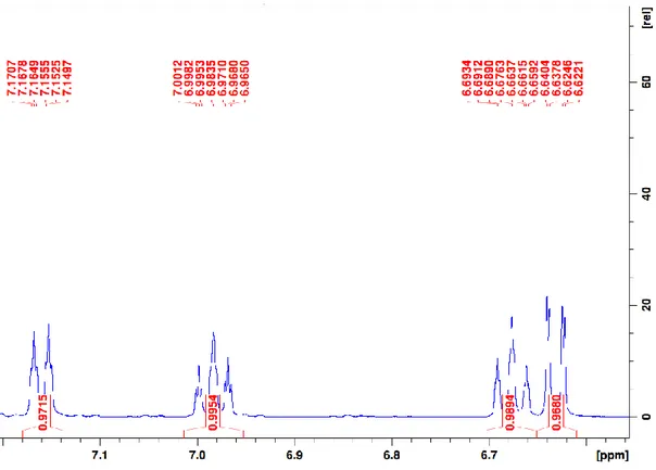
of MeCN ... 66 Figure 2.2. Top views of the molecular diagrams for complexes 1a-NCMe (left) and 1i-NCMe (middle), and side view for complex 1i-NCMe (right). Thermal ellipsoids are shown at the 50% probability level. Hydrogen atoms in all diagrams and Me groups in the side view of 1i-NCMe have been omitted for clarity. ... 72 Figure 2.3. Top and side views of the molecular diagram for complex 1d. Thermal ellipsoids are shown at the 50% probability level; hydrogens in both views and the P-substituents in the side view have been omitted for clarity. ... 73 Figure 2.4. Top view of the molecular diagram for complex 1f and side view for a portion of the dimer. Thermal ellipsoids are shown at the 50% probability level; hydrogens are omitted for clarity. The side view shows the ligands around only one Ni atom. ... 73 Figure 2.5. Top view of the molecular diagram for complex 1k. Thermal ellipsoids are shown at the 50% probability level; hydrogens are omitted for clarity. ... 73 Figure 2.6. Aromatic region of the 1H, 1H{19F}, and 1H{31P} NMR spectra of 1f, disclosing J
HF,
JHH and JHP couplings. ... 77
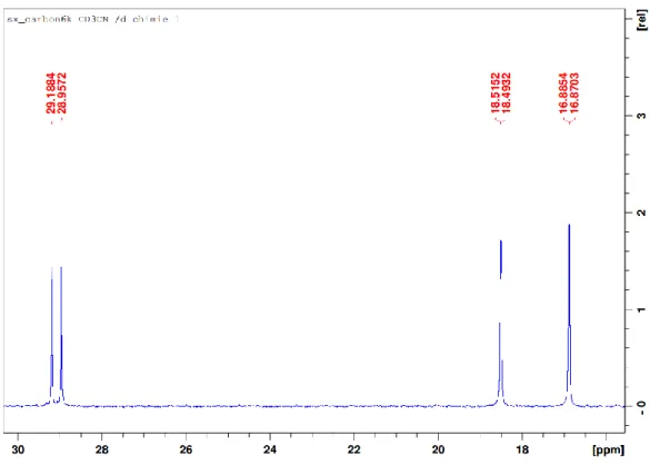
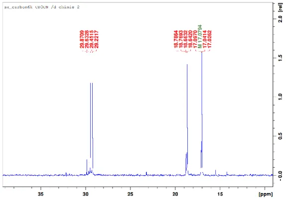
Figure 2.7. Selected regions in the 13C{1H} NMR of 1f displaying J
CF and JCP couplings. ... 78
Figure S2.1: UV-vis Spectra of the dimer derived from PhOP(i-Pr)2 ([Dimer] = ½ [Ni] = 0.833
mM) and of the MeCN adduct ([Monomer] = 0.555 mM) generated by addition of 10 eq. MeCN in Toluene at 22 °C... 88 Figure S2.2: Full 1H NMR spectrum of 1a in CD
3CN ... 90
Figure S2.3: 1H NMR spectrum of 1a in CD
3CN; focus on aliphatic region ... 90
Figure S2.4: 1H NMR spectrum of 1a in CD
3CN; focus on aromatic region ... 91
Figure S2.5: Full 13C{1H} NMR spectrum of 1a in CD
3CN ... 91
Figure S2.6: 13C{1H} NMR spectrum of 1a in CD
3CN; focus on aliphatic region ... 92
Figure S2.7: 13C{1H} NMR spectrum of 1a in CD
3CN; focus on aromatic region ... 92
Figure S2.8: 31P{1H} NMR spectrum of 1a in CD
3CN ... 93
XXIV
Figure S2.10: Full 1H NMR spectrum of 1b(major)+1b’(minor) in CD
3CN... 94
Figure S2.11: 1H NMR spectrum of 1b+1b’ in CD
3CN; focus on aliphatic region ... 94
Figure S2.12: 1H NMR spectrum of 1b+1b’ in CD
3CN; focus on aromatic region ... 95
Figure S2.13: Full 13C{1H} NMR spectrum of 1b+1b’ in CD
3CN ... 95
Figure S2.14: 13C{1H} NMR spectrum of 1b+1b’ in CD
3CN; focus on aliphatic region ... 96 Figure S2.15: 13C{1H} NMR spectrum of 1b+1b’ in CD3CN; focus on aromatic region (I) ... 96
Figure S2.16: 13C{1H} NMR spectrum of 1b+1b’ in CD
3CN; focus on aromatic region (II) ... 97
Figure S2.17: 31P{1H} NMR spectrum of 1b+1b’ in CD 3CN ... 97 Figure S2.18: 19F NMR spectrum of 1b+1b’ in CD 3CN... 98 Figure S2.19: 19F NMR spectrum of 1b+1b’ in CD 3CN; focus on 1b ... 98 Figure S2.20: 19F NMR spectrum of 1b+1b’ in CD 3CN; focus on 1b’ ... 99
Figure S2.21: HSQC spectrum of 1b+1b’ in CD3CN; focus on aromatic region ... 99
Figure S2.22: Full 1H NMR spectrum of 1c in CD
3CN ... 100
Figure S2.23: 1H NMR spectrum of 1c in CD
3CN; focus on aliphatic region (I) ... 100
Figure S2.24: 1H NMR spectrum of 1c in CD
3CN; focus on aliphatic region (II) ... 101
Figure S2.25: 1H NMR spectrum of 1c in CD
3CN; focus on aromatic region ... 101
Figure S2.26: Full 13C{1H} NMR spectrum of 1c in CD
3CN ... 102
Figure S2.27: 13C{1H} NMR spectrum of 1c in CD
3CN; focus on aliphatic region... 102
Figure S2.28: 13C{1H} NMR spectrum of 1c in CD
3CN; focus on aromatic region ... 103
Figure S2.29: 31P{1H} NMR spectrum of 1c in CD
3CN ... 103
Figure S2.30: HSQC spectrum of 1c in CD3CN ... 104
Figure S2.31: Full 1H NMR spectrum of 1d in CD
3CN... 104
Figure S2.32: 1H NMR spectrum of 1d in CD
3CN; focus on aliphatic region (I) ... 105
Figure S2.33: 1H NMR spectrum of 1d in CD
3CN; focus on aliphatic region (II) ... 105
Figure S2.34: 1H NMR spectrum of 1d in CD
3CN; focus on aromatic region ... 106
Figure S2. 35: Full 13C{1H} NMR spectrum of 1d in CD
3CN ... 106
Figure S2.3613C{1H} NMR spectrum of 1d in CD
3CN; focus on aliphatic region ... 107
Figure S2.37: 13C{1H} NMR spectrum of 1d in CD
3CN; focus on aromatic region ... 107
Figure S2.38: 31P{1H} NMR spectrum of 1d in CD
3CN ... 108
Figure S2.39: HSQC spectrum of 1d in CD3CN; focus on aromatic region ... 108
Figure S2.40: Full 1H NMR spectrum of 1e in CD
XXV Figure S2.41: 1H NMR spectrum of 1e in CD
3CN; focus on aliphatic region ... 109
Figure S2.42: 1H NMR spectrum of 1e in CD
3CN; focus on aromatic region ... 110
Figure S2.43: Full 13C{1H} NMR spectrum of 1e in CD
3CN ... 110
Figure S2.44: 13C{1H} NMR spectrum of 1e in CD
3CN; focus on aliphatic region... 111
Figure S2.45: 13C{1H} NMR spectrum of 1a in CD
3CN; focus on aromatic region ... 111
Figure S2.46: 31P{1H} NMR spectrum of 1e in CD
3CN ... 112
Figure S2.47: HSQC spectrum of 1a in CD3CN; focus on aromatic region ... 112
Figure S2.48: Full 1H NMR spectrum of 1f in CD
3CN ... 113
Figure S2.49: 1H NMR spectrum of 1f in CD
3CN; focus on aliphatic region ... 113
Figure S2.50: 1H NMR spectrum of 1f in CD
3CN; focus on aromatic region ... 114
Figure S2.51: 1H{19F} NMR spectrum of 1f in CD
3CN; focus on aromatic region ... 114
Figure S2.52: 1H{19F} NMR spectrum of 1f in CD
3CN; focus on aromatic region ... 115
Figure S2.53: Full 13C{1H} NMR spectrum of 1f in CD
3CN ... 115
Figure S2.54: 13C{1H} NMR spectrum of 1f in CD
3CN; focus on aliphatic region ... 116
Figure S2.55: 13C{1H} NMR spectrum of 1f in CD
3CN; focus on aromatic region (I) ... 116
Figure S2.56: 13C{1H} NMR spectrum of 1f in CD
3CN; focus on aromatic region (II) ... 117
Figure S2.57: 31P{1H} NMR spectrum of 1f in CD 3CN ... 117 Figure S2.58: 31F{1H} NMR spectrum of 1f in CD 3CN ... 118 Figure S2.59: 31F{1H} NMR spectrum of 1f in CD 3CN; focus on C5Ar-F ... 118 Figure S2.60: 31F{1H} NMR spectrum of 1f in CD 3CN; focus on C3Ar-F ... 119
Figure S2.61: HSQC spectrum of 1f in CD3CN; focus on aromatic region... 119
Figure S2.62: Full 1H NMR spectrum of 1i-NCMe in CD
3CN ... 120
Figure S2.63: 1H NMR spectrum of 1i-NCMe in CD
3CN; focus on aliphatic region ... 120
Figure S2.64: 1H NMR spectrum of 1i-NCMe in CD
3CN; focus on O-CH3 and aromatic region
... 121 Figure S2.65: Full 13C{1H} NMR spectrum of 1i-NCMe in CD
3CN ... 121
Figure S2.66: 13C{1H} NMR spectrum of 1i-NCMe in CD
3CN; focus on aliphatic region ... 122
Figure S2.67: 13C{1H} NMR spectrum of 1i-NCMe in CD
3CN; focus on aromatic region ... 122
Figure S2.68: 31P{1H} NMR spectrum of 1i-NCMe in CD
3CN ... 123
Figure S2.69: HSQC spectrum of 1i-NCMe in CD3CN; focus on aromatic region ... 123
Figure S2.70: Full 1H NMR spectrum of 1j in CD
XXVI Figure S2.71: 1H NMR spectrum of 1j in CD
3CN; focus on aliphatic region ... 124
Figure S2.72: 1H NMR spectrum of 1j in CD
3CN; focus on aromatic region ... 125
Figure S2.73: Full 13C{1H} NMR spectrum of 1j in CD
3CN ... 125
Figure S2.74: 13C{1H} NMR spectrum of 1a in CD
3CN; focus on aliphatic region ... 126
Figure S2.75: 13C{1H} NMR spectrum of 1j in CD
3CN; focus on aromatic region ... 126
Figure S2.76: 31P{1H} NMR spectrum of 1j in CD
3CN ... 127
Figure S2.77: HSQC spectrum of 1j in CD3CN; focus on aromatic region... 127
Figure S2.78: Full 1H NMR spectrum of 1k in CD
3CN... 128
Figure S2.79: 1H NMR spectrum of 1k in CD
3CN; focus on aliphatic region ... 128
Figure S2.80: 1H NMR spectrum of 1k in CD
3CN; focus on aromatic region ... 129
Figure S2.81: Full 13C{1H} NMR spectrum of 1k in CD
3CN ... 129
Figure S2.82: 13C{1H} NMR spectrum of 1k in CD
3CN; focus on aliphatic region ... 130
Figure S2.83: 13C{1H} NMR spectrum of 1k in CD
3CN; focus on aromatic region ... 130
Figure S2.84: 31P{1H} NMR spectrum of 1k in CD
3CN ... 131
Figure S2.85: HSQC spectrum of 1k in CD3CN; focus on aromatic region ... 131
Figure S2.86: Solid state structure of 1a-NCMe. Thermal ellipsoids are shown at the 50% probability level; hydrogen atoms are omitted for clarity. ... 132 Figure S2.87: Solid state structure of 1b. Thermal ellipsoids are shown at the 50% probability level; hydrogen atoms are omitted for clarity ... 132 Figure S2.88: Side view of 1b. Thermal ellipsoids are shown at the 50% probability level; hydrogen atoms and isopropyl substituents are omitted for clarity ... 133 Figure S2.89: Solid state structure of 1c. Thermal ellipsoids are shown at the 50% probability level; hydrogen atoms are omitted for clarity ... 133 Figure S2.90: Solid state structure of 1e. Thermal ellipsoids are shown at the 50% probability level; hydrogen atoms are omitted for clarity ... 134 Figure S2.91: Solid state structure of 1j. Thermal ellipsoids are shown at the 50% probability level; hydrogen atoms are omitted for clarity ... 134 Figure S2.92: Proposed energy surface for the inversion of the bending in ModelPhenol ... 160 Figure 3.1. Plot of ln(1-conv.) as a function of time, and rate constants under the assumption of a 1st order cyclonickelation in MeCN at 70 °C with various amines and [amine]. ... 170
XXVII
Figure 3.2. Plot of ln(1-conv.) as a function of time for the cyclonickelation of PhOP(i-Pr)2 with 1
equiv Ni precursor and 1equiv i-Pr2NEt in MeCN at 80 °C. ... 175
Figure 3.3. Nickelation rates of various 3-X-C6H5OP(i-Pr)2 species in MeCN at 80 °C. ... 175
Figure 3.4. Hammett plot for the nickelation of 3-X-C6H5OP(i-Pr)2 species in MeCN at 80 °C.
... 176 Figure 3.5. Eyring plot displaying rates at 50, 60, 70 and 80 °C for the metalation of PhOP(i-Pr)2
in MeCN. ... 176 Figure 3.6. Molecular diagram of [(THF)6Ni2(µ-Br)3][(Et3N)NiBr3]. Thermal ellipsoids are shown
at the 50% probability level. Hydrogen atoms have been omitted for clarity. ... 177 Figure 3.7. Energies (calculated at the M06 level of theory and expressed in kcal/mol) for optimized structures of the potential ground states for the model compound (PhOPMe2)NiBr2(NCMe). ... 180
Figure 3.8. Energies (calculated at the M06 level of theory and expressed in kcal/mol) for optimized structures as the potential ground states for the pentacoordinated model compound (PhOPMe2)NiBr2(NCMe)2. ... 181
Figure 3.9. Energies and kinetic barriers (calculated at the M06 level of theory and expressed in kcal/mol) for the species resulting from C-H oxidative addition. ... 182 Figure 3.10. Energies (calculated at the M06 level of theory and expressed in kcal/mol) of the optimized transition states for the deprotonation on the 1cis, 1trans and 3tet surfaces as well as the
ion pair on the triplet surface. ... 183 Figure 3.11. Optimized structures for the {PhOP(i-Pr)2}NiBr2(NCMe) isomers and their energies
calculated at the M06 level of theory. Energies are expressed in kcal/mol. ... 185 Figure 3.12. Optimized structures for the P(i-Pr)2 intermediates on the 1trans surface and their
energies calculated at the M06 level of theory. Energies are expressed in kcal/mol. ... 186 Figure S3.1: 1H spectrum of {C 6H5OP(i-Pr)2}2NiBr2 in CDCl3 ... 198 Figure S3.2: 31P spectrum of {C 6H5OP(i-Pr)2}2NiBr2 in CDCl3 ... 199 Figure S3.3: 1H spectrum of {C 6H5OP(i-Pr)2}2NiBr2 in C6D6 ... 199 Figure S3.4: 31P spectrum of {C 6H5OP(i-Pr)2}2NiBr2 in C6D6 ... 200 Figure S3.5: 31P spectrum of {C
6H5OP(i-Pr)2}2NiBr2 in PhMe ... 200
Figure S3.6: 31P spectrum of {C
XXVIII Figure S3.7: 31P NMR spectrum of {C
6H5OP(i-Pr)2}2NiBr2 + excess C6H5OP(i-Pr)2 ligand in
MeCN ... 201 Figure S3.8: 31P NMR spectrum of {C
6H5OP(i-Pr)2}2NiBr2 + excess Et3N in MeCN ... 201
Figure S3.9: 1H NMR spectrum of {C 6D5OP(i-Pr)2}2NiBr2 in CDCl3 ... 202 Figure S3.10: 2H NMR spectrum of {C 6D5OP(i-Pr)2}2NiBr2 in CHCl3 ... 202 Figure S3.11: 1H NMR spectrum of {4-Cl-C 6H4-OP(i-Pr)2}2NiBr2 in CDCl3. ... 203 Figure S3.12: 13C NMR spectrum of {4-Cl-C 6H4-OP(i-Pr)2}2NiBr2 in CDCl3. ... 203 Figure S3.13: 31P NMR spectrum of {4-Cl-C 6H4-OP(i-Pr)2}2NiBr2 in CDCl3. ... 204
Figure S3.14: HSQC spectrum of {4-Cl-C6H4-OP(i-Pr)2}2NiBr2 in CDCl3. ... 204
Figure S3.15: 31P NMR spectrum of {C
6H5-OP(i-Pr)2}2NiBr2 in C6D5CD3 at –30 °C... 205
Figure S3.16: 31P NMR spectrum of {C
6H5-OP(i-Pr)2}2NiBr2 in CD3CN at –30 °C ... 205
Figure S3.17: 31P NMR spectrum of a 1:1 mixture of C
6H5-OP(i-Pr)2 and (i-PrCN)NiBr2 in CD3CN
at –30 °C ... 206 Figure S3.18: Crude mixture of {C6H5-OP(i-Pr)2}2NiBr2 + 1 equiv. Et3N in PhMe heated at 80 °C
for 16 h ... 206 Figure S3.19: Crude mixture of {C6H5-OP(i-Pr)2}2NiBr2 + 1 equiv. Et3N in PhMe heated at 100
°C for 16 h ... 207 Figure S3.20: Crude mixture of C6H5-OP(i-Pr)2 + 1 equiv. (i-PrCN)NiBr2 + 1 equiv. Et3N in PhMe
heated at 80 °C for 16 h ... 207 Figure S3.21: Crude mixture of C6H5-OP(i-Pr)2 + 1 equiv. (i-PrCN)NiBr2 + 1 equiv. Et3N in PhMe heated at 100 °C for 16 h ... 208 Figure S3.22: 31P spectrum of the reaction mixture after 15 mins with 1 equiv. Et
3N. Focus on the
Ni-complex region ... 209 Figure S3.23: 31P spectrum of the reaction mixture after 15 mins with 4 equiv. Et
3N. Focus on the
Ni-complex region ... 209 Figure S3.24: 31P spectrum of the reaction mixture after 15 mins with 1 equiv. i-Pr
2NEt. Focus on
the Ni-complex region ... 210 Figure S3.25: 31P spectrum of the reaction mixture after 15 mins with 1 equiv. i-Pr
2NEt. Full
spectrum. ... 210 Figure S3.26: 31P spectrum of the reaction mixture at the end of the reaction with 1 equiv. i-Pr
2NEt.
XXIX Figure S3.27: 1H NMR spectra in CDCl
3 of various mixtures of L2NiBr2 and of the H/D scrambling
experiment. Focus on the aromatic region. ... 212 Figure S3.28: Heating {C6H5OP(i-Pr)2}2NiBr2 in CD3CN or C6D5CD3 shows no ortho-D
incorporation on the ligand. ... 213 Figure S3.29: 2H{1H} NMR spectrum of the crystals arising from the scrambling of {C
6H5
OP(i-Pr)2}2NiBr2 with CD3CN, showing <1% D incorporation into the ortho positions. ... 214
Figure S3.30: 2H{1H} NMR spectrum of the crystals arising from the scrambling of {C
6H5
OP(i-Pr)2}2NiBr2 with C6D5CD3, where ortho D could not be detected. ... 214
Figure S3.31: Heating {C6D5OP(i-Pr)2}2NiBr2 in CH3CN or C6H5CH3 shows ortho-H
incorporation on the ligand via H/D scrambling with the solvent. ... 215 Figure S3.32: 13C{1H} NMR spectrum of the crystals arising from the scrambling of {C
6D5
OP(i-Pr)2}2NiBr2 with CH3CN, showing no D incorporation into the i-Pr moiety of the ligand. ... 216
Figure S3.33: 13C{1H} NMR spectrum of the crystals arising from the scrambling of {C
6D5
OP(i-Pr)2}2NiBr2 with C6H5CH3, showing no D incorporation into the i-Pr moiety of the ligand. ... 216
Figure S3.34: ESI-MS mass pattern in the sample (a), theoretical mass pattern for the expected M+
= [C17H30Br2N2NiOP]+ (b), and overlap of the experimental pattern and M+ – 1 (c) ... 217
Figure S3.35: ESI-MS mass pattern in the sample (a), theoretical mass pattern for the expected M+
= [C19H33Br2N3NiOP]+ (b), and overlap of the experimental pattern and M+ + 2 (c). ... 218
Figure S3.36: Molecular diagram for the bimetallic cation [(Me3N-PhOPR2)2Ag(µ-Br)3] (the
counter anion is Br-). Thermal ellipsoids are shown at the 50% probability level. Hydrogens atoms
have been omitted for clarity and the Methyls of the i-Pr in the diagram on the right. ... 220 Figure S3.37: Molecular diagram for the zwitterionic compound (Me3N-PhOPR2)NiX3. Thermal
ellipsoids are shown at the 50% probability level. Hydrogen atoms have been omitted for clarity. ... 220 Figure S3.38: Time profile for the cyclonickelation in MeCN at 70 °C in the presence of various equivalents of amine. ... 221 Figure S3.39: Progress of the cyclonickelation for various 3-X-C6C4OP(i-Pr)2 in MeCN at 80 °C
(X = OMe, Me, H, Cl and COOMe). ... 221 Figure S3.40: Plot of ln(1-conv.) as a function of time, and rate constants for various 3-X-C6H4OP(i-Pr)2 in MeCN at 80 °C (X = OMe, Me, H, Cl and COOMe). ... 222
XXX
Figure S3.41: Plot of ln(1-conv.) as a function of time, and rate constant for the di-substituted ligand 3,5-MeO2-C6H3OP(i-Pr)2 in MeCN at 70 °C. ... 222
Figure S3.42: Plot of ln(1-conv.) as a function of time and rate constants for the cyclonickelation of C6H5OP(i-Pr)2 and its deuterated parent C6D5OP(i-Pr)2 in MeCN at 80 °C displaying a high
Kinetic Isotope Effect. ... 223 Figure S3.43: Plot of ln(1-conv.) as a function of time and rate constants for the cyclonickelation of C6H5OP(i-Pr)2 in MeCN at temperatures ranging from 50 °C to 80 °C. ... 223
Figure 4.1. Top view of the molecular diagram for complex 2a. Thermal ellipsoids are shown at the 50% probability level; hydrogen atoms are omitted for clarity. ... 235 Figure 4.2. Top view of the molecular diagram for complex 2e. Thermal ellipsoids are shown at the 50% probability level; hydrogen atoms are omitted for clarity. ... 239 Figure 4.3. Side views of the molecular diagrams for complexes 2a (top), 2b (middle) and 2c (bottom). Thermal ellipsoids are shown at the 50% probability level; hydrogen atoms and P-substituents are omitted for clarity. ... 251 Figure 4.4. Side view of the molecular diagram for complex 2f. Thermal ellipsoids are shown at the 50% probability level; hydrogen atoms and P-substituents are omitted for clarity. ... 253 Figure 4.5. Molecular diagram for complex 4. Thermal ellipsoids are shown at the 50% probability level; hydrogen atoms are omitted for clarity. ... 253 Figure S4.1: Full 1H NMR spectrum of 2a in CD
3CN. ... 272
Figure S4.2: 1H NMR spectrum of 2a in CD
3CN, focus on the aliphatic region. ... 273
Figure S4.3: 1H NMR spectrum of 2a in CD
3CN, focus on the aromatic region. ... 273
Figure S4.4: Full 13C{1H} NMR spectrum of 2a in CD
3CN. ... 274
Figure S4.5: 13C{1H} NMR spectrum of 2a in CD
3CN, focus on the aliphatic region. ... 274
Figure S4.6: 13C{1H} NMR spectrum of 2a in CD
3CN, focus on the aromatic region. ... 275
Figure S4.7: COSY NMR spectrum of 2a in CD3CN, focus on the aromatic region. ... 275
Figure S4.8: NOESY NMR spectrum of 2a in CD3CN, focus on the aromatic/aromatic interactions.
... 276 Figure S4.9: HSQC NMR spectrum of 2a in CD3CN, focus on the aromatic region. ... 276
Figure S4.10: {1H}31P NMR spectrum of 2a in CD
3CN. ... 277
Figure S4.11: Full 1H NMR spectrum of 2b in CD
3CN, focus on the aromatic region. ... 278
Figure S4.12: 1H NMR spectrum of 2b in CD
XXXI Figure S4.13: 1H NMR spectrum of 2b in CD
3CN, focus on the aromatic region. ... 279
Figure S4.14: Full 13C{1H} NMR spectrum of 2b in CD
3CN. ... 279
Figure S4.15: 13C{1H} NMR spectrum of 2b in CD
3CN, focus on the aliphatic region. ... 280
Figure S4.16: 13C{1H} NMR spectrum of 2b in CD
3CN, focus on the aromatic region. ... 280
Figure S4.17: COSY NMR spectrum of 2b in CD3CN, focus on the aromatic region. ... 281
Figure S4.18: NOESY NMR spectrum of 2b in CD3CN, focus on the aliphatic/aromatic
interactions. ... 281 Figure S4.19: NOESY NMR spectrum of 2b in CD3CN, focus on the aromatic/aromatic
interactions. ... 282 Figure S4.20: HSQC NMR spectrum of 2b in CD3CN, focus on the aromatic region. ... 282
Figure S4.21: 31P{1H} NMR spectrum of 2b in CD
3CN. ... 283
Figure S4.22: Full 1H NMR spectrum of 2c in CD
3CN. ... 284
Figure S4.23: 1H NMR spectrum of 2c in CD
3CN, focus on the aliphatic region. ... 285
Figure S4.24: 1H NMR spectrum of 2c in CD
3CN, focus on the aromatic region. ... 285
Figure S4.25: Full 13C{1H} NMR spectrum of 2c in CD
3CN. ... 286
Figure S4.26: 13C{1H} NMR spectrum of 2c in CD
3CN, focus on the aliphatic region. ... 286
Figure S4.27: 13C{1H} NMR spectrum of 2c in CD
3CN, focus on the aromatic region. ... 287
Figure S4.28: COSY NMR spectrum of 2c in CD3CN, focus on the aromatic region. ... 287
Figure S4.29: NOESY NMR spectrum of 2c in CD3CN, focus on the aliphatic/aromatic
interactions. ... 288 Figure S4.30: HSQC NMR spectrum of 2c in CD3CN, focus on the aromatic region. ... 288
Figure S4.31: 31P{1H} NMR spectrum of 2c in CD
3CN. ... 289
Figure S4.32: Full 1H NMR spectrum of 2e in CD
3CN. ... 290
Figure S4.33: 1H NMR spectrum of 2e in CD
3CN, focus on the aliphatic region. ... 290
Figure S4.34: 1H NMR spectrum of 2e in CD
3CN, focus on the aromatic region. ... 291
Figure S4.35: Full 13C{1H} NMR spectrum of 2e in CD
3CN. ... 291
Figure S4.36: 13C{1H} NMR spectrum of 2e in CD
3CN, focus on the aliphatic region. ... 292
Figure S4.37: 13C{1H} NMR spectrum of 2e in CD
3CN, focus on the aromatic region. ... 292
Figure S4.38: COSY NMR spectrum of 2e in CD3CN, focus on the aromatic region. ... 293
Figure S4.39: COSY NMR spectrum of 2e in CD3CN, focus on the aromatic/aromatic interactions.
XXXII
Figure S4.40: HSQC NMR spectrum of 2e in CD3CN, focus on the aromatic region. ... 294
Figure S4.41: 31P{1H} NMR spectrum of 2e in CD
3CN. ... 294
Figure S4.42: Full 1H NMR spectrum of 2f in CD
3CN. ... 295
Figure S4.43: 1H NMR spectrum of 2f in CD
3CN, focus on the aliphatic region. ... 295
Figure S4.44: 1H NMR spectrum of 2f in CD
3CN, focus on the aromatic region. ... 296
Figure S4.45: Full 13C{1H} NMR spectrum of 2f in CD
3CN. ... 296
Figure S4.46: 13C{1H} NMR spectrum of 2f in CD
3CN, focus on the aliphatic region. ... 297
Figure S4.47: 13C{1H} NMR spectrum of 2f in CD
3CN, focus on the aromatic region. ... 297
Figure S4.48: COSY NMR spectrum of 2f in CD3CN, focus on the aromatic region. ... 298
Figure S4.49: NOESY NMR spectrum of 2f in CD3CN, focus on the aliphatic/aromatic
interactions. ... 298 Figure S4.50: NOESY NMR spectrum of 2f in CD3CN, focus on the aromatic/aromatic
interactions. ... 299 Figure S4.51: HSQC NMR spectrum of 2f in CD3CN, focus on the aromatic region. ... 299
Figure S4.52: 31P{1H} NMR spectrum of 2f in CD
3CN. ... 300
Figure S4.53: Full 1H NMR spectrum of 2g in C
6D6. ... 301
Figure S4.54: 1H NMR spectrum of 2g in C
6D6, focus on the aliphatic region. ... 301
Figure S4.55: 1H NMR spectrum of 2g in C
6D6, focus on the allylic region. ... 302
Figure S4.56: 1H NMR spectrum of 2g in C
6D6, focus on the aromatic region. ... 302
Figure S4.57: Full 13C{1H} NMR spectrum of 2g in C
6D6. ... 303
Figure S4.58: 13C{1H} NMR spectrum of 2g in C
6D6, focus on the aliphatic region. ... 303
Figure S4.59: 13C{1H} NMR spectrum of 2g in C
6D6, focus on the allylic region. ... 304
Figure S4.60: 13C{1H} NMR spectrum of 2g in C
6D6, focus on the aromatic region. ... 304
Figure S4.61: COSY NMR spectrum of 2g in C6D6, focus on the aliphatic region. ... 305
Figure S4.62: COSY NMR spectrum of 2g in C6D6, focus on the allylic region. ... 305
Figure S4.63: COSY NMR spectrum of 2g in C6D6, focus on the aromatic region. ... 306
Figure S4.64: NOESY NMR spectrum of 2g in C6D6, focus on the aliphatic/allylic and
allylic/allylic interactions. ... 306 Figure S4.65: NOESY NMR spectrum of 2g in C6D6, focus on the aromatic/aliphatic and
aromatic/allylic interactions. ... 307 Figure S4.66: HSQC NMR spectrum of 2g in C6D6, focus on the aliphatic region. ... 307