HAL Id: hal-01382712
https://hal.sorbonne-universite.fr/hal-01382712
Submitted on 17 Oct 2016HAL is a multi-disciplinary open access archive for the deposit and dissemination of sci-entific research documents, whether they are pub-lished or not. The documents may come from teaching and research institutions in France or abroad, or from public or private research centers.
L’archive ouverte pluridisciplinaire HAL, est destinée au dépôt et à la diffusion de documents scientifiques de niveau recherche, publiés ou non, émanant des établissements d’enseignement et de recherche français ou étrangers, des laboratoires publics ou privés.
Microsized Sn as Advanced Anodes in Glyme-Based
Electrolyte for Na-Ion Batteries
Biao Zhang, Gwenaëlle Rousse, Dominique Foix, Romain Dugas, Daniel Alves
Dalla Corte, Jean-marie Tarascon
To cite this version:
Biao Zhang, Gwenaëlle Rousse, Dominique Foix, Romain Dugas, Daniel Alves Dalla Corte, et al.. Microsized Sn as Advanced Anodes in Glyme-Based Electrolyte for Na-Ion Batteries. Advanced Ma-terials, Wiley-VCH Verlag, 2016, �10.1002/adma.201603212�. �hal-01382712�
Article type: Communication
Microsized Sn as advanced anodes in glyme-based electrolyte for Na-ion batteries
Biao Zhang, Gwenaëlle Rousse, Dominique Foix, Romain Dugas, Daniel Alves Dalla Corte and Jean-Marie Tarascon*
Dr. B. Zhang, Prof. G. Rousse, Dr. D. Foix, Dr. R. Dugas, Dr. D. Alves Dalla Corte, Prof. J.M. Tarascon
Chimie du Solide-Energie, UMR 8260, Collège de France, 11 Place Marcelin Berthelot, 75231 Paris Cedex 05, France
E-mail: [email protected]
Dr. B. Zhang, Prof. G. Rousse, Dr. D. Foix, Dr. R. Dugas, Dr. D. Alves Dalla Corte, Prof. J.M. Tarascon
Réseau sur le Stockage Electrochimique de l’Energie (RS2E), FR CNRS 3459, 80039 Amiens, France
Dr. B. Zhang, Prof. G. Rousse, Dr. D. Foix, Dr. R. Dugas, Dr. D. Alves Dalla Corte, Prof. J.M. Tarascon
ALISTORE-European Research Institute, 80039 Amiens, France Prof. G. Rousse, Prof. J.M. Tarascon
Sorbonne Universités - UPMC Univ Paris 06, 4 place Jussieu, F-75005 Paris, France. Dr. D. Foix
IPREM/ECP (UMR 5254), University of Pau, 2 av. Pierre Angot, 64053 Pau cedex 9,France
Submitted to
The concept of Na-ion batteries was proposed in 1980s but was abandoned later due to its
lower energy density than Li-ion batteries. The revival of Na-ion technology in recent years
relies on the low cost and natural abundance of Na sources, which will bring a roughly 30%
decrease in the cost compared to Li-ion batteries, albeit at ~15% penalty of energy density
currently [1]. Thanks to intensive studies carried out in the past several years, researchers have
been able to develop several high performance cathode materials for Na-ion batteries which
are structurally close to the ones successfully developed for Li-ion batteries. Polyanionic
Na3V2(PO4)2F3,[2] Na3V2(PO4)3,[3,4] layered P2-type Na2/3(Fe1/2Mn1/2)O2 [5] and prussian white
Na1.92Fe[Fe(CN)6] [6] deliver energy densities close to those presently obtained in Li-ion
batteries. Turning to the anodes, hard carbon is considered as one of the most promising
candidates.[7,8] However, it has a low reversible capacity of around 250 mAh/g with a
relatively high potential of ~0.28 V vs Na in average, i.e. showing a poorer behavior than
graphite anode in Li-ion battery. Developing high performance anodes are urgently required
for Na-ion batteries in order to catch up the energy density of Li-ion batteries. At this stage,
research efforts are devoted to two directions: one is aiming at increasing the capacity and
decreasing the average potential of hard carbon by tailoring its microstructure,[9–12] while
considerable work are also conducted on searching for new candidates among which alloy
anodes are most attractive.
Alloy anodes, including Sn,[13] Sb [14] and Pb[15] have been widely studied due to their
high capacities, yet the mild toxicity of Sb and Pb makes them less promising for practical
applications. In contrast, Sn is an environmental friendly material and abundant in nature. The
commercialization of Li-ion batteries based on Sn-Co alloys as negative electrodes was even
considered.[16] Moreover, Sn has a high theoretical capacity of 847 mAh/g through the
formation of Na15Sn4 alloys.[17] Coupling with aforementioned cathode, such as
Na2/3(Fe1/2Mn1/2)O2, it is possible to build a Na-ion battery exhibiting an energy density close
Sn is the fast capacity fading arising from the large volume change of around 420% during
cycling.[19,20] Extensive studies have been put on fabrication of Sn/C composites, which have
greatly improved the cyclic stability by maintaining the electrode integrity. [21–23] A drawback
of these nanostructured materials is their low density that will lead to a low volumetric energy
density for batteries. Moreover, large irreversible capacity is observed in the 1st cycle due to
the solid electrolyte interface (SEI) formation on the high surface area of nanosized materials.
Therefore, microsized Sn particles with stable cycling stability are eagerly expected in view
of practical application. Instead of preparing nanoparticles, herein we report the highly stable
bulk Sn anodes through the use of glyme-based electrolyte so as to achieve both high
gravimetric and volumetric energy densities.
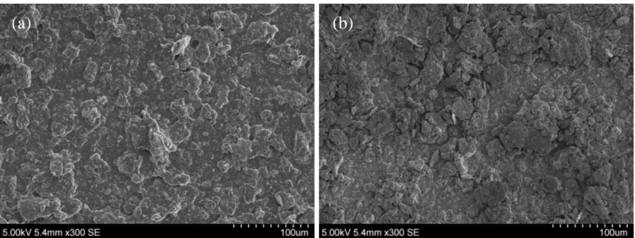
Microsized Sn particle (325 mesh) was used directly as active materials. It was
ball-milled with 20wt.% Carbon SP for 30 mins. The short time ball milling did not reduce much
the particle size: the particles remain 5-50 µm as revealed by scanning electron microscopy
(SEM). Carbon SP are attached on the surface of Sn to establish a fast electron transfer path in
the electrode (Figure S1). The mixture was then dispersed in a carboxymethylcellulose
sodium (CMC) aqueous solution, which was coated on a Cu foil and dried under vacuum
before being transferred into Ar glove box. The electrochemical performances were evaluated
in coin cells with Na metal as both reference and counter electrodes. Carbonate-based
electrolytes have been successfully commercialized in Li-ion batteries, and similar systems
are currently widely explored for Na-ion batteries. Several typical protocols including
ethylene carbonate (EC)/dimethyl carbonate (DMC), EC/diethyl carbonate (DEC) and
propylene carbonate (PC) as solvents with 1M NaPF6 or NaClO4 as salts have been reported. [24]
Since Sn particles have catalytic effects on the decomposition of EC, [25] here battery tests
were firstly performed in 1M NaPF6 in PC electrolytes. 5% fluoroethylene carbonate (FEC) is
used as additives to stabilize Na metal and also help to establish a stable SEI. [26] Around 2.7
Submitted to
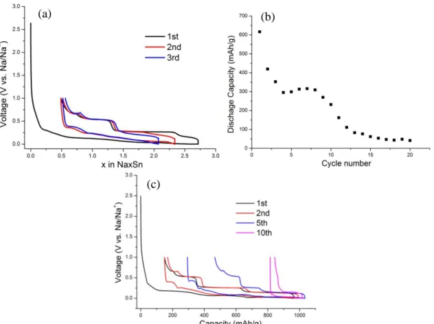
However, the capacity degrades quickly down to only 300 mAh/g in the first 10 cycles and
further reduces to below 100 mAh/g after 20 cycles (Figure S2a,b). This observation is not
surprising considering the huge volume change of Sn during Na-Sn alloy process. [27] The
repeating sodiation and de-sodiation results in the disconnection of Sn particles in the
electrode, as revealed by the fracturing of the cycled electrodes observed by SEM (Figure S3).
Insulating active materials from current collector gives rise to the loss of Sn activity and
therefore a fast capacity fade.
To combat this issue several approaches have been previously tried. Among them is the
confinement of nanosized Sn particles in conductive carbon phases which offer additional free
space for volume change, but also bring issues of low density and high irreversible capacity.
Another one deals with the development of efficient binders such as poly(acrylic acid), [28]
and poly (9,9-dioctylfluorene-co-fluorenone-co-methylbenzoic ester) (PFM) [29] to constrain
the nanosized Sn particles so that stable capacity retention up to 20 cycles was achieved.
Owing to their limited successes, we decided to explore different electrolyte formulations in
our search for a potential solution for the long cyclic stability of microsized Sn. Glyme-based
electrolyte have been reported for graphite anodes in Na-ion battery to enable the
co-intercalation of solvated Na, [30,31] and for improving the cyclic stability of conversion
anodes.[32] Similar system is applied here to check the performance in Sn alloy anode. 1M
NaPF6 in diethylene glycol dimethyl ether (diglyme, DGME) was used as electrolyte to
compare with carbonate-based electrolyte systems. As shown in the Figure 1a, 3.83 Na is
involved in the first reduction which is slightly higher than theoretical value due to the Na
consumption in SEI formation. During the following reduction, 3.54 Na is removed
corresponding to a Coulombic efficiency of 92%. This value is much higher than the value of
~70% previously reported for nanostructured Sn/C composites.[21–23] Using microsized Sn
greatly reduces the contact area between electrolyte and active materials and thus improves
increase since the irreversible capacity of carbon SP additive is only of 8% in DGME
electrolyte as compared to 63% in PC/FEC (Figure S4).
Once the first charge is achieved, the following cycles present an increasing Coulombic
efficiency and achieve a value of more than 99% starting from 5th cycle. Their voltage
profiles resemble the one in the first cycle but with a gradual capacity decrease in the initial
10 cycles. Nevertheless, the capacity becomes stable afterwards and the electrodes deliver a
capacity as high as 768 mAh/g after 100 cycles, corresponding to a capacity retention of 88%
(Figure 1b). The cell also shows a good power rate as shown in the inset of Figure 1a.
Increasing the cycling rate from 0.1C to 1C only slightly decreases the capacity. A high
capacity of 622 mAh/g could be obtained even under a current density of 2C (equal to 1.69
A/g), proving that the electrode could sustain respectable rate capabilities. Last but not least,
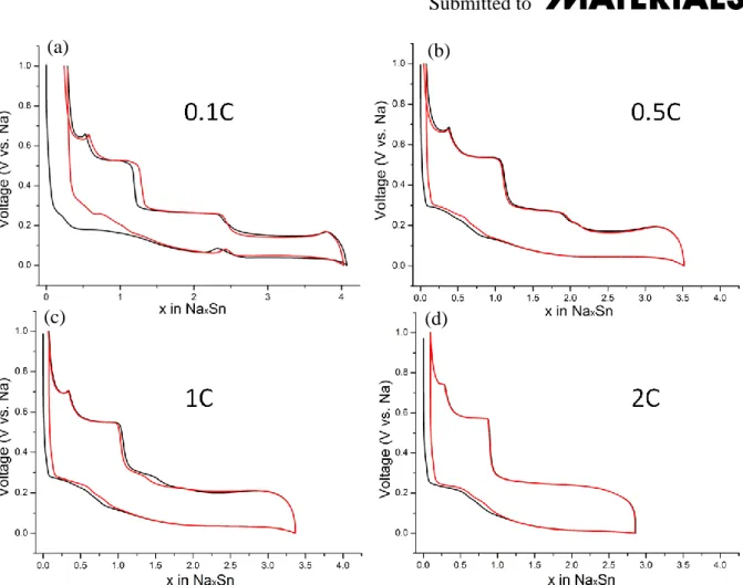
we should mention that the profile of the V= f(x) curve shows numerous plateaus which are
more prominent on charge than on discharge and associated to phase changes. Therefore,
somewhat unusual are the artifacts preceding these plateaus, namely on charge where we
observe a voltage overshooting which is present once the material is recharged and that
becomes sharper when reaching the last forming phase at the end of the charge process ( ~
0.67V). Such spikes are usually reminiscent of phases whose formation (e.g
nucleation/growth process) is kinetically limited. To test this hypothesis we studied the effect
of the current density on the amplitude of these peaks. Indeed, increasing the current results in
a decrease of the spikes implying that these kinetically limited phases are not any longer
forming (Figure S5). To make an analogy, we could say that for less feeling the holes on the
road, we must move quickly, because we do not leave time the wheels to penetrate deeply; the
holes being the potential well. Similarly, this could explain why the number of plateaus is
inferior to the number of phases reported.
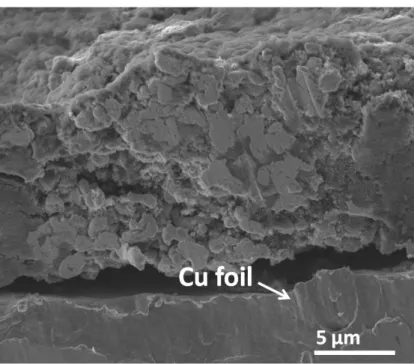
To explore the reasons behind the stability of Sn in DGME as compared to PC-based
Submitted to
Figure 1b, and Figure S6). The electrode cycled in DGME shows a smooth surface, in sharp
contrast to rough surface observed in the electrode tested in PC. Although some cracks are
observed, the integrity of the electrode is mainly preserved without the appearance of isolated
particles. A close view into the electrode reveals that the particles are surrounded by thin SEI
films, which prevent the separation of the active materials from the matrix. The composition
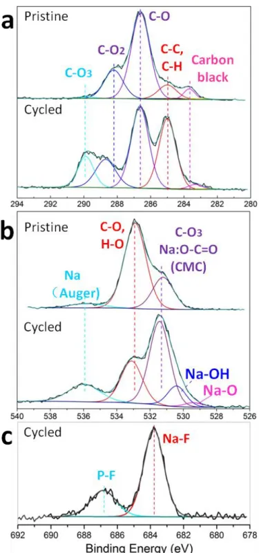
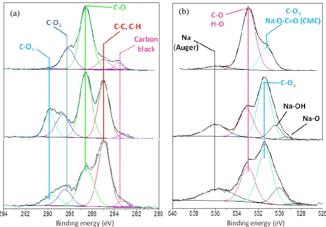
of the films was examined by X-ray photoelectron spectroscopy (XPS), and the deconvoluted
C1s, O1s and F1s spectra for the pristine and cycled electrode are shown in Figure 2. A peak
at 283.7 eV from conductive carbon SP is observed in C1s spectra. The peaks at 285, 286.6
and 288.2 eV in the fresh electrode are assigned to C-C (H), C-O and C-O2 species presented
in CMC binder. [33] The proportion of C-C(H) peak at 285 eV increases prominently after long
cycling: an indication of the formation of sodium alkoxides (RCH2ONa) groups as a result of
reduction of DGME. [34] Note also the appearance of another peak at 290 eV corresponding to
the formation of Na2CO3. This assignment is confirmed by the O1s spectra which shows the
growth of a carbonate specie peak at 531 eV.[35] Moreover, a comparison of the O1s spectra
before and after cycling (Figure 2b) suggests the formation of NaOH and Na2O. Turning to
the F1s spectrum it shows upon cycling the emergence of two peaks at 684 and 687 eV
corresponding to NaF and P-F species, respectively. They can simply be ascribed to the
reduction of NaPF6 salts in the electrolyte, emphasizing the role of salts in formation of
protecting film.[34]
Overall, from the above analysis, the SEI films consist of both organic (RCH2ONa)
and inorganic (NaF, NaPF6, Na2O, Na2CO3 and phosphates) components. For comparative
purposes the composition of SEI formed in PC electrolyte was also investigated (Figure S7).
The SEI is made of similar species but in different relative proportions suggesting that the SEI
growing process is different in both cases. A possible reason could be nested in the high
solubility of the sodium oxides and carbonates in PC[36] due to the mild Lewis acid character
observed previously by SEM. Although we could not accurately quantify the absolute
amounts of some species because of interferences with CMC, this study highlights the
importance of building a continuous and dense SEI for improving the cyclic performance of
alloy anodes, where glyme-based electrolytes show great advantages.
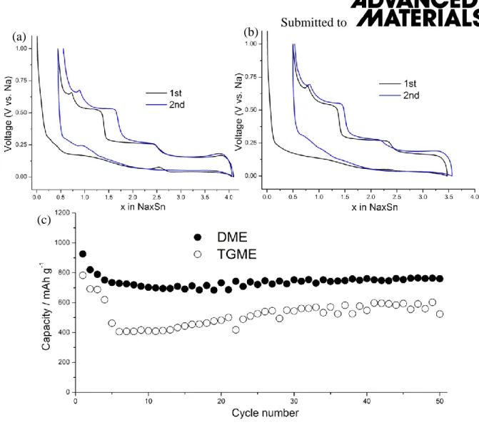
The family of glyme solvents includes several other members with variation in molecule’s chain lengths, including dimethoxyethane (monoglyme, DME) and tetraethylene
glycol dimethyl ether (tetraglyme, TGME). Using both DME and DGME solvents give
similar capacities, but the utilization of TGME results in a decrease of the reversible
capacities to 523 mAh/g after 50 cycles (Figure S8). This difference may simply be rooted in
their ionic conductivity which decreases with the ether chain length due to a greater capturing
of the Na+ ions, hence leading to a lower mobility. Nevertheless, the change from DGME to
DME and TGME does not affect much the stability. Sn electrode preserves the stable cyclic
performance in the electrolyte of both 1M NaPF6/DME and 1M NaPF6/TGME, confirming
the benefits of moving from carbonate to glyme solvents for Sn anodes.
The voltage-composition profile for the Sn electrode shows a cascade-like behavior with
several plateaus indicating the complexity of the electrochemical reactivity of Sn against Na
that enlists a multi-steps process. Previous studies by density functional theory (DFT)
calculations[19] suggest the existence of a few intermediate phases including NaSn5, NaSn and
Na9Sn4 prior to reach the fully sodiated Na15Sn4. Except Na15Sn4, however, none of the other
phases that are observed during electrochemical alloying in carbonate electrolyte agree with
the known equilibrium ones.[17]
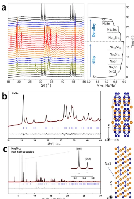
To figure out the phase transitions in glyme-based electrolyte, in situ X-ray diffraction
(XRD) measurements were performed in a Swagelok type cell equipped with a Be window
and XRD patterns were collected for every 0.25 Na change (Figure 3a). The phase changes in
DGME are similar to what was reported in carbonate electrolyte, suggesting that the
Submitted to
process with Sn. Numerous NaxSn phases do exist, but identifying their exact composition
from in situ XRD measurements is not trivial because of Na consumption associated to the
SEI formation which introduces inaccuracy on the Na content. To address this issue, we
decided, in light of our recent work, to chemically prepare these alloys by reactive Na-ball
milling.[37] Several NaxSn compositions were tried. For x < 1 we could not, alike
electrochemical measurements, stabilize any single phase materials. In contrast powders made
of the reported Na0.2Sn or ~Na0.5Sn phases and remaining Sn were always obtained. The use
of longer ball milling times lead to the amorphisation of the NaxSn while not affecting the
amount of Sn secondary phase. We then focused on the synthesis of Na rich NaxSn alloys
with x≥1 and successfully prepared the NaSn, Na9Sn4 and Na15Sn4 compositions as single
phases (Figure 3).
It is worthwhile mentioning that pure and nicely crystallized NaSn phase (Figure S9)
having an orthorhombic structure could also be obtained by annealing at 100°C for 24 hours
the amorphous powder recovered from an electrochemical cell discharged down to 0.11V
(xelec ~ 1.5). Further pursuing the ball milling experiments with a Na to Sn ratio of 2.25
(Na9Sn4), we obtained a crystalline phase with an XRD powder pattern analog to that obtained
by discharging a cell down to 0.05 V. However, this pattern differs from the one previously
reported for the same composition which crystallizes in the Cmcm space group, [17] thus we embarked in a depth structural study of this “new polymorph” .
The Synchrotron X-ray diffraction pattern of Na9Sn4 powder prepared by ball-milling
is shown in Figure 3c. The measurement was done using a wavelength of 0.4959 Å that
corresponds to 25 keV, i.e. below the Sn K-edge absorption energy (29.209 keV). The pattern
can clearly be not indexed in the previously reported Cmcm structure, therefore we have here
the evidence of a new Na9Sn4 polymorph. Interestingly, a similar pattern was previously
attributed to Na5Sn2 by comparison with the pattern of Li5Sn2.[38,39] To the best of our
intensities for patterns measured below either a Be window or a kapton film, using lab X-ray
diffraction. We therefore started from the Li5Sn2 model to refine our synchrotron data. All
Na9Sn4 peaks can be indexed in a rhombohedral unit cell, space group R-3m, with refined
lattice parameters a= 5.43958(2) Å, c= 22.43084(7) Å. Our first Rietveld refinements were
done with Na atoms are distributed on three crystallographic sites, Na1 on the Wyckoff
positions 3b (0 , 0, ½) , and Na2 and Na3 both on the 6c position (0, 0, z), with z=0.358 and
z=0.208 for Na2 and Na3, respectively. Sn atoms are located on a single 6c position with z=
0.0637. This structural model corresponds to a chemical formula Na5Sn2; however refining
the refinement showed a huge and unrealistic Biso temperature factors of 30 Å2 for Na1. This
indicated that the electronic density is too large on this site. The refinement using this model
and imposing identical Biso for all Na atoms is shown in Figure S10 and presents intensity
problems with some reflections with too much intensity (e.g. (012)), while others are too low
(eg. (101)). Therefore we refined the occupancy of the Na1 atom, still imposing the Biso
identical for all Na atoms. This led to a crystallographic occupancy of 0.45(5), a value close to
the theoretical value 0.5 that would correspond to the Na9Sn4 chemical formula. Note
however that the resulting Biso are pretty large, indicating that Na is highly mobile. The final
refinement also took into account an anisotropic strain, with S400=0.209(6), S004= 0.00158(5)
and S112= 0.125(3) according to Stephen’s notations.[40] This indicates lattice parameters
fluctuations perpendicular to the [001] direction. The final refinement is shown in Figure 3c
and is greatly improved compared to the Na5Sn2 model, and Table S1 gathers crystallographic
information of Na9Sn4.
Figure 3c shows the structures of the Na9Sn4 polymorph reported in the present paper.
The structure of previously reported Na9Sn4 and the one of Na5Sn2 (Li5Sn2–type structure) are
given in Figure S11. The common feature to all structures is that they present Sn-Sn dimers
(Sn-Sn distance of 2.85 Å) all oriented in the same direction, and separated by Na atoms. Our
Submitted to
c lattice parameter (c= 22.43084(7) Å for Na9Sn4 vs 22.257 Å reported for Na5Sn2[39]). This
may come as a surprise, as our structure presents less Na; most likely this difference comes
from electrostatic interactions. The two Na9Sn4 polymorphs-the rhombohedral one reported in
this paper and the orthorhombic Cmcm structure- differ in the way Sn-Sn dimers are stacked,
as highlighted in Figure S11.
For sake of completion we explore the Na-rich end phase and found that both ball
milling and electrochemical sodiation can easily lead to the formation of the Na15Sn4 phase
which was refined using the Rietveld method (Figure S12). Note that this Na15Sn4 (x<3.75)
phase can reversibly be reoxidized via a reacting path enlisting the successive formation of
Na9Sn4, and then NaSn phases (Figure 3a). The Na poor phase of NaxSn (x<1) is not seen on
charging, and NaSn is directly transformed into Sn. Nucleation of Sn from the poorly
crystallized NaSn phase leads to voltage oscillations around 0.67 V. The Na-Sn alloy and
de-alloy processes follow the same traces afterwards, as indicated by identical voltage profiles
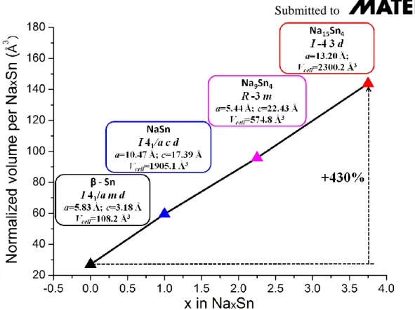
shown in Figure1a. The lattice parameters of the NaxSn phases formed during Na-Sn alloy are
summarized in Figure 4, and the volume at different sodiation stages are calculated. It reveals
an almost linear volume expansion along with the increase in the Na contents. A fully
transformation from Sn to Na15Sn4 would lead to a 430% increase in the volume, consistent
with previous observation under in situ TEM and by DFT calculations.[19,20] The results
shown here offer some implications to rational design of even better Sn-based electrodes for
addressing the volume change during cycling.
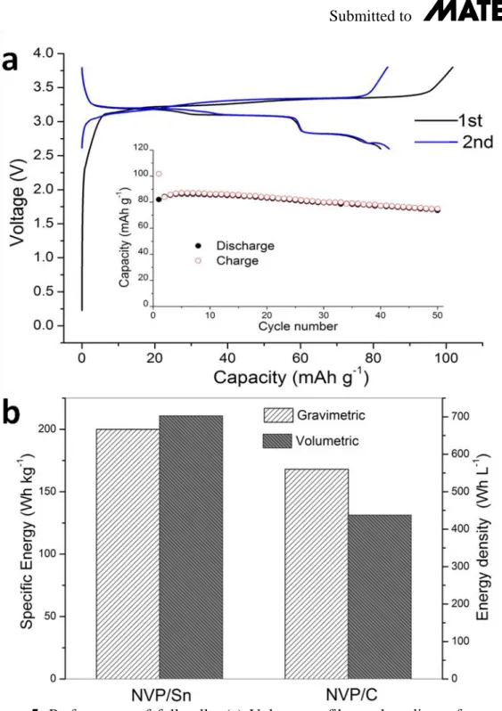
To test the benefit of Sn negative electrodes, full Na-ions cells using Na3V2(PO4)3
(denoted hereafter NVP) as positive electrode and 1M NaPF6/DGME as electrolyte were
assembled. Based on the reversible capacity of NVP vs. Na which equals 90 mAh/g (Figure
S13), Sn/NVP Na-ion cell were assembled with a mass ratio of NVP to Sn of 8.05 and cycled
at a rate of C/5. The cell shows an initial charge capacity of 102 mAh/g and a discharge
due to the Na consumption during the SEI formation at the Sn anode. Otherwise the cell
shows a decent capacity retention since it maintains 90% of the initial capacity after 50 cycles.
Further improvements rely on both the optimization of NVP cathode and balancing the ratio
of cathode to anode. In the 50th cycle, the cell delivers an energy density of 200 Wh/kg taking
account the mass of active materials in both the cathode and anode. For comparison, we made
a NVP/C Na–ion cell using 1M NaPF6 in EC/DMC electrolyte and similar cycling protocol
with therefore a mass ratio of NVP to hard carbon is 3. The NVP/C cell cycled between
3.8-1.5V shows an average voltage of 3.1 V (Figure S13c). A capacity of 72 mAh/g (NVP) is
obtained in the 50th cycle, giving an energy density of 168 Wh/kg calculated based on the
total mass of NVP and hard carbon. This highlight the benefit of using Sn as anode since a
19% improvement in gravimetric energy density is obtained when compared to NVP/C cells
(Figure 5b). The volumetric energy densities were calculated using the theoretic density of Sn
(7.3 g/cm3), and NVP (3.3 g/cm3), respectively, and a value of 1.6 g/cm3 for hard carbon.
Thanks to the high density Sn, NVP/Sn shows a volumetric energy density of 703 Wh/L, 61%
increase compared to 438 Wh/L for NVP/C cell.
In summary, we have reported glyme based electrolytes enable high reversible capacity
of Sn anode for Na-ion batteries. The improvement in the stability mainly relies on the
formation of protecting films which prevent the formation of insulating domains of active
materials. Moreover, the Na-Sn phases during electrochemical alloying are examined through
in situ XRD characterization to clarify several intermediate phases such as amorphous NaSn.
In particular, a new polymorph of Na9Sn4 is found and its crystal structure is analyzed by
synchrotron X-ray diffraction. Lastly, prototype full cells using Sn anode and NVP cathode
are assembled. They demonstrate the great advantages of using Sn instead of hard carbon as
anodes since enchantments of 19% and 61% increase in gravimetric and volumetric energy
Submitted to
glyme electrolyte requires further evaluation, we anticipate the results presented here will
have strong implication in developing Sn based high performance anodes for Na-ion batteries.
Experimental Section
Preparation of Sn electrode: Commercial Sn particles from Alfa (325 mesh) were used as
active materials. Sn and Carbon SP with a mass ratio of four were filled into a hard steel
ball-milled jar under Ar. They were ball ball-milled in a Spex 8000M ball-miller with a ball to powder
ratio of 10. The mixture was then mixed with 10% CMC binder in de-ionized water, and the
resulting slurry was coated in Cu foil to make a tape. After drying under vacuum at 60oC,
electrodes with diameter of 11 mm were punched from the tape to assemble coin cells. A
typical loading of the active materials in one electrode was 2 mg/cm2. Note that the capacity
does not change much when the loading increased to 4mg/cm2 which delivers similar capacity
retention (Figure S14).
Synthesis of NaxSn alloys by ball milling: Stoichiometric amounts of bulk Na metal (Sigma)
and Sn powder were filled into the hard steel ball-milled jar in glove box. Stainless steel ball
diameter of 12mm was used and they were milled in a Spex 8000M ball miller for 1h to
obtain NaxSn loose powder.
Electrochemical tests: Electrolytes are prepared by adding NaPF6 (Stella Chemifa) to various
solvents, including PC (BASF), DME, DGME and TGME, to make 1 molar solution. 5wt%
FEC (98%, Alfa) was added in PC electrolyte. Anhydrous glymes were purchased from
Sigma-Aldrich with a purity of more than 99.5%. All the electrolytes were dried by molecular
sieve (4Å, Sigma-Aldrich) to make sure the water content to be lower than 20ppm as
confirmed by Karl-Fisher titration (Metrohm 899 coulometer). The electrochemical
performance was examined in coin cells with a piece of glass fiber (Whatman, GF/D) as
separator and Na metal as counter electrode. NVP was used a cathode in a full cell to couple
with Sn and hard carbon anode. A conventional solid-state reaction was used to prepare NVP
measurement. Sn/Carbon SP/CMC slurry was coated on the Be window. The cells are
galvanostatically cycled in VMP system (Biologic S.A., Claix, France).
Characterizations: XRD patterns were recorded using either a Bruker D8-Advance
Diffractometer with Cu-Kα radiation (λ1= 1.54056 Å, λ2= 1.54439 Å) equipped with a
LynxEye detector operating at 40 kV and 40 mA. For synchrotron XRD, the powder was
placed in a 0.7 mm diameter capillary, and the pattern was recorded in transmission geometry
using a wavelength of 0.4959 Å on the ID22 beamline at ESRF (Grenoble, France). All
powder patterns were refined using the Rietveld method[43] as implemented in the FullProf
program.[44] Peak shapes were described using a modified Thompson-Cox-Hastings
pseudo-Voigt function, and the background was modeled with a 12-coeficients Chebyshev polynom.
For the synchrotron pattern, absorption was taken into account with µR=0.5 (R being the
radius of our capillary). For in situ patterns recorded behind a Be window, an absorption
correction was applied in the refinements.
The morphology of electrodes after cycling are checked by SEM (Philips, XL30). To prepare
the electrodes, the cells are disassembled in the glovebox and washed with DMC and DGME
for PC and DGME electrolyte, respectively. XPS measurements were carried out with a
Kratos Axis Ultra spectrometer, using a focused monochromatized Al K radiation (h=1486.6 eV). The XPS spectrometer was directly connected through a transfer chamber to an argon dry box, in order to avoid moisture/air exposure of the samples. The analysed area of
the samples was 300×700 µm². Peaks were recorded with a constant pass energy of 20 eV.
The pressure in the analysis chamber was around 5×10⁻⁹ mbar. Short acquisition time spectra
were recorded before and after each normal experiment to check that the samples did not
suffer from degradation during the measurements. The binding energy scale was calibrated
from the hydrocarbon contamination using the C1s peak at 285.0 eV. Core peaks were
Submitted to
optimized by a weighted least-squared fitting method using 70% Gaussian, 30% Lorentzian
lineshapes.
Supporting Information
Supporting Information is available online from the Wiley Online Library or from the author.
Acknowledgements
The RS2E (Réseau sur le Stockage Electrochimique de l’Energie) network is acknowledged for the financial support of this work through the ANR project Storex (ANR-10-LABX-76-01). The authors thank Carlotta Giacobbe for the collection of synchrotron X-ray diffraction patterns at European Synchrotron Radiation Facility on ID22, and Renald David for providing Na3V2(PO4)3.
Received: ((will be filled in by the editorial staff)) Revised: ((will be filled in by the editorial staff)) Published online: ((will be filled in by the editorial staff))
[1] D. Larcher, J. Tarascon, Nat. Chem. 2015, 7, 19.
[2] M. Bianchini, N. Brisset, F. Fauth, F. Weill, E. Elkaim, E. Suard, C. Masquelier, L.
Croguennec, Chem. Mater. 2014, 26, 4238.
[3] R. Klee, M. J. Aragón, R. Alcántara, J. L. Tirado, P. Lavela, Eur. J. Inorg. Chem. 2016,
Doi:10.1002/ejic.201600241.
[4] C. Zhu, P. Kopold, P. A. van Aken, J. Maier, Y. Yu, Adv. Mater. 2016, 28, 2409.
[5] N. Yabuuchi, M. Kajiyama, J. Iwatate, H. Nishikawa, S. Hitomi, R. Okuyama, R. Usui,
Y. Yamada, S. Komaba, Nat. Mater. 2012, 11, 512.
[6] L. Wang, J. Song, R. Qiao, L. A. Wray, M. A. Hossain, Y. De Chuang, W. Yang, Y.
Lu, D. Evans, J. J. Lee, S. Vail, X. Zhao, M. Nishijima, S. Kakimoto, J. B.
Goodenough, J. Am. Chem. Soc. 2015, 137, 2548.
[7] C. Bommier, T. W. Surta, M. Dolgos, X. Ji, Nano Lett. 2015, 15, 5888.
[8] S. Komaba, W. Murata, T. Ishikawa, N. Yabuuchi, T. Ozeki, T. Nakayama, A. Ogata,
K. Gotoh, K. Fujiwara, Adv. Funct. Mater. 2011, 21, 3859.
Mater. 2016, 6, 1501588.
[10] G. Hasegawa, K. Kanamori, N. Kannari, J. ichi Ozaki, K. Nakanishi, T. Abe,
ChemElectroChem 2015, 2, 1917.
[11] J. Zhang, W. Lv, Y. Tao, Y. B. He, D. W. Wang, C. H. You, B. Li, F. Kang, Q. H.
Yang, Energy Storage Mater. 2015, 1, 112.
[12] Y. Li, Y.-S. Hu, H. Li, L. Chen, X. Huang, J. Mater. Chem. A 2015, 4, 96.
[13] Z. Li, J. Ding, D. Mitlin, Acc. Chem. Res. 2015, 48, 1657.
[14] A. Darwiche, C. Marino, M. T. Sougrati, B. Fraisse, L. Stievano, L. Monconduit, J. Am.
Chem. Soc. 2012, 134, 20805.
[15] A. Darwiche, R. Dugas, B. Fraisse, L. Monconduit, J. Power Sources 2016, 304, 1.
[16] J. Li, D. B. Le, P. P. Ferguson, J. R. Dahn, Electrochim. Acta 2010, 55, 2991.
[17] L. D. Ellis, T. D. Hatchard, M. N. Obrovac, J. Electrochem. Soc. 2012, 159, A1801.
[18] M. Dahbi, N. Yabuuchi, K. Kubota, K. Tokiwa, S. Komaba, Phys. Chem. Chem. Phys.
2014, 16, 15007.
[19] V. L. Chevrier, G. Ceder, J. Electrochem. Soc. 2011, 158, A1011.
[20] J. W. Wang, X. H. Liu, S. X. Mao, J. Y. Huang, Nano Lett. 2012, 12, 5897.
[21] B. Zhang, J. Huang, J.-K. Kim, Adv. Funct. Mater. 2015, 25, 5222.
[22] Y. Xu, Y. Zhu, Y. Liu, C. Wang, Adv. Energy Mater. 2013, 3, 128.
[23] Y. Liu, N. Zhang, L. Jiao, J. Chen, Adv. Mater. 2015, 27, 6702.
[24] A. Ponrouch, E. Marchante, M. Courty, J.-M. Tarascon, M. R. Palacín, Energy Environ.
Sci. 2012, 5, 8572.
[25] J. S. Bridel, S. Grugeon, S. Laruelle, J. Hassoun, P. Reale, B. Scrosati, J. M. Tarascon,
J. Power Sources 2010, 195, 2036.
[26] R. Dugas, B. Zhang, P. Rozier, J. M. Tarascon, J. Electrochem. Soc. 2016, 163, A867.
[27] J. Wang, C. Eng, Y.-C. K. Chen-Wiegart, J. Wang, Nat. Commun. 2015, 6, 7496.
Submitted to
commun. 2012, 21, 65.
[29] K. Dai, H. Zhao, Z. Wang, X. Song, V. Battaglia, G. Liu, J. Power Sources 2014, 263,
276.
[30] B. Jache, P. Adelhelm, Angew. Chemie - Int. Ed. 2014, 53, 10169.
[31] H. Kim, J. Hong, Y.-U. Park, J. Kim, I. Hwang, K. Kang, Adv. Funct. Mater. 2015, 25,
534.
[32] K. Zhang, Z. Hu, X. Liu, Z. Tao, J. Chen, Adv. Mater. 2015, 27, 3305.
[33] D. M. Seo, C. C. Nguyen, B. T. Young, D. R. Heskett, J. C. Woicik, B. L. Lucht, J.
Electrochem. Soc. 2015, 162, A7091.
[34] Z. W. Seh, J. Sun, Y. Sun, Y. Cui, ACS Cent. Sci. 2015, 1, 449.
[35] M. A. Munoz-Marquez, M. Zarrabeitia, E. Castillo-Martinez, A. Eguia-Barrio, T. Rojo,
M. Casas-Cabanas, ACS Appl. Mater. Interfaces 2015, 7, 7801.
[36] M. Moshkovich, Y. Gofer, D. Aurbach, J. Electrochem. Soc. 2001, 148, E155.
[37] B. Zhang, R. Dugas, G. Rousse, P. Rozier, A. M. Abakumov, J.-M. Tarascon, Nat.
Commun. 2016, 7, 10308.
[38] Z. Du, R. A. Dunlap, M. N. Obrovac, J. Alloys Compd. 2014, 617, 271.
[39] L. Baggetto, P. Ganesh, R. P. Meisner, R. R. Unocic, J.-C. Jumas, C. A. Bridges, G. M.
Veith, J. Power Sources 2013, 234, 48.
[40] P. Stephens, J. Appl. Crystallogr. 1999, 32, 281.
[41] K. Du, H. Guo, G. Hu, Z. Peng, Y. Cao, J. Power Sources 2013, 223, 284.
[42] F. Lalere, V. Seznec, M. Courty, R. David, J. N. Chotard, C. Masquelier, J. Mater.
Chem. A 2015, 3, 16198.
[43] H. M. Rietveld, J. Appl. Crystallogr. 1969, 2, 65.
[44] J. Rodríguez-Carvajal, Physica B 1993, 192, 55.
Figure1. Performance of Sn electrode in 1M NaPF6/DGME electrolyte. (a) Voltage profiles
with their rate capability (inset), where 1C equal to 847 mA/g; (b) cyclic stability at 250 mA/g.
The morphology of the electrodes after 100 cycles is shown in the insets of (b).The arrows
Submitted to
Figure 2. XPS spectra of pristine electrode and after cycling in 1M NaPF6/DGME: (a) C1s;
Figure 3. Phase transformation of Sn electrode. (a) In situ XRD patterns during the first
cycle; (b) Rietveld refinement of NaSn prepared by ball milling and its crystal structure
(right); (c) Rietveld refinement of synchrotron pattern of Na9Sn4 and its crystal structure
(right). The red crosses, black continuous line and bottom gray line represent the observed,
calculated, and difference patterns, respectively. Vertical blue tick marks are the Bragg
positions. The Na and Sn atoms are colored in orange and blue, respectively. The shortest
Submitted to
Figure 4. Volume change during Na-Sn alloy. Insets show the crystal structure of the phases,
Figure 5. Performance of full cells. (a) Voltage profiles and cyclic performance (inset) of
NVP/Sn; (b) Comparison of the gravimetric and volumetric energy densities of NVP/Sn and
Submitted to
Microsized Sn presents stable cyclic performance in glyme based electrolyte, which brings 19% increase in energy density of Sn/Na3V2(PO4)2 cells as compared to the cells using
hard carbon anode. The Na-Sn intermediate phases are also clarified.
Keyword: Tin, electrolyte, microsize , Na ion battery
B. Zhang, G. Rousse, D. Foix, R. Dugas, D. Alves Dalla Corte, J.M. Tarascon*
Microsized Sn as advanced anodes in glyme-based electrolyte for Na-ion batteries
Copyright WILEY-VCH Verlag GmbH & Co. KGaA, 69469 Weinheim, Germany, 2013.
Supporting Information
for Adv. Mater., DOI: 10.1002/adma.Microsized Sn as advanced anodes in glyme-based electrolyte for Na-ion batteries
Biao Zhang, Gwenaëlle Rousse, Dominique Foix, Romain Dugas, Daniel Alves Dalla Corte and Jean-Marie Tarascon*
Dr. B. Zhang, Prof. G. Rousse, Dr. D. Foix, Dr. R. Dugas, Dr. D. Alves Dalla Corte, Prof. J.M. Tarascon
Chimie du Solide-Energie, UMR 8260, Collège de France, 11 Place Marcelin Berthelot, 75231 Paris Cedex 05, France
E-mail: [email protected]
Dr. B. Zhang, Prof. G. Rousse, Dr. D. Foix, Dr. R. Dugas, Dr. D. Alves Dalla Corte, Prof. J.M. Tarascon
Réseau sur le Stockage Electrochimique de l’Energie (RS2E), FR CNRS 3459, 80039 Amiens, France
Dr. B. Zhang, Prof. G. Rousse, Dr. D. Foix, Dr. R. Dugas, Dr. D. Alves Dalla Corte, Prof. J.M. Tarascon
ALISTORE-European Research Institute, 80039 Amiens, France Prof. G. Rousse, Prof. J.M. Tarascon
Sorbonne Universités - UPMC Univ Paris 06, 4 place Jussieu, F-75005 Paris, France. Dr. D. Foix
Submitted to
Figure S1 SEM images of Sn/Carbon SP after ball milling for 30 mins at (a) low and (b) high
magnifications.
Figure S2 Electrochemical performance of Sn electrode in 1M NaPF6/PC electrolyte with 5%
FEC additives. (a) Voltage profiles and (b) cycling stability under 100 mA/g; (c) capacity at a
current density of 25 mA/g. Note that reducing the current density allows fully sodiation of Sn,
which improves a lot the capacity in the first two cycles but still shows a fast capacity
degradation.
(a) (b)
(a) (b)
Figure S3 SEM images of Sn electrodes (a) before cycling and (b) after cycling in 1M NaPF6
PC/FEC electrolyte.
Figure S4 Voltage profiles of Csp vs Na in the electrolyte of (a) 1M NaPF6 in DGME and (b)
1M NaPF6 in PC/FEC.
(a) (b)
Submitted to
Figure S5 Voltage profiles of Sn electrode cycled under various current densities: (a) 0.1C; (b)
0.5C; (c) 1C and (d) 2C. 1C=847 mA/g.
(c) (d)
Figure S6 Cross section image of Sn electrode after cycling in DGME electrolyte. Integrity of
Submitted to
Figure S7 Comparison of (a) C1s and (b) O1s spectra for fresh electrode (top), after cycling in
1M NaPF6/DGME (middle) and cycling in 1M NaPF6/PC with 5% FEC (bottom).
Figure S8 Voltage profiles of Sn electrode cycling in (a) 1M NaPF6/DME and (b) 1M
NaPF6/TGME; (c) Cyclic stability in the two electrolytes.
(a) (b)
Submitted to
Figure S9. Rietveld refined XRD pattern of NaSn obtained electrochemically and annealed at
100 oC under Ar. The red crosses, black continuous line and bottom gray line represent the
observed, calculated, and difference patterns, respectively. Vertical blue tick bars mark the
Figure S10 Rietveld refinements of the synchrotron X-ray diffraction pattern using the Na5Sn2
model (a) and the Na9Sn4 model presented in the paper. The inset highlight the improvement
of the refinement on the (101) and (012) reflections when Na1 is only half occupied (chemical
composition Na9Sn4). The red crosses, black continuous line and bottom gray line represent
the observed, calculated, and difference patterns, respectively. Vertical blue tick bars mark the
Submitted to c b a c a
a) Na
5Sn
2R-3m
b) Na
9Sn
4R-3m
c) Na
9Sn
4Cmcm
c a Na1 Na1Figure S11 Structure of Na5Sn2 (a), and the two polymorphs of Na9Sn4, in R-3m (this work, b)
and Cmcm space groups (c). Na and Sn atoms are shown as orange and dark blue balls,
Figure S12. XRD Rietveld refinement of the Na15Sn4 formed by discharging to 0V in the in
situ cell. The red crosses, black continuous line and bottom gray line represent the observed,
calculated, and difference patterns, respectively. Vertical blue tick bars mark the Bragg
Submitted to
Figure S13 (a) Voltage profiles of NVP vs Na in 1M NaPF6/DGME electrolyte and (b) the
corresponding cyclic stability; (c) voltage profiles of NVP/C full cell in 1M
NaPF6/(EC/DMC) electrolyte and (d) its capacity retention in the first 50 cycles.
(a) (b)
(c)
Figure S14 Cyclic performance of high loading Sn electrode (4 mg/cm2) in 1M NaPF6/DGME
electrolyte.
Table S1. Structural parameters for Na9Sn4 deduced from the Rietveld refinement of the synchrotron
X-ray diffraction pattern.
Space Group: R -3 m
a= 5.43958(2) Å, c= 22.43084(7) Å
V= 574.788(3) Å3 density= 2.954 g/cm3 Z=1
Atom Wyckoff site x y z Occupancy B(Å2)
Na1 3b 0 0 1/2 0.5 7.20(4)
Na2 6c 0 0 0.35759(10) 1.0 7.20(4) Na3 6c 0 0 0.21034(10) 1.0 7.20(4) Sn 6c 0 0 0.06356(2) 1.0 2.066(9)