UNIVERSITÉ DE MONTRÉAL
SEISMIC EVALUATION AND RETROFIT OF EXISTING CONCENTRICALLY BRACED STEEL FRAMES IN CANADA
YASAMAN BALAZADEH MINOUEI
DÉPARTEMENT DES GÉNIES CIVIL, GÉOLOGIQUE ET DES MINES ÉCOLE POLYTECHNIQUE DE MONTRÉAL
THÈSE PRÉSENTÉE EN VUE DE L’OBTENTION DU DIPLÔME DE PHILOSOPIAE DOCTOR
(GÉNIE CIVIL) AOÛT 2017
UNIVERSITÉ DE MONTRÉAL
ÉCOLE POLYTECHNIQUE DE MONTRÉAL
Cette thèse intitulée :
SEISMIC EVALUATION AND RETROFIT OF EXISTING CONCENTRICALLY BRACED STEEL FRAMES IN CANADA
présentée par : BALAZADEH MINOUEI Yasaman en vue de l’obtention du diplôme de : Philosophiae Doctor a été dûment acceptée par le jury d’examen constitué de :
M. LÉGER Pierre, Ph. D., président
Mme KOBOEVIC Sanda, Ph. D., membre et directrice de recherche M. TREMBLAY Robert, Ph. D., membre et codirecteur de recherche M. GOULET James-A., D.Sc., membre
DEDICATION
Dedicated to my parents, Maryam Taghizadeh-Milani and Alireza Balazadeh-Minouei and my husband, Ali Imanpour
ACKNOWLEDGEMENTS
I would also like to show my gratitude to Professor Sanda Koboevic. Her support and financial assistance through the Natural Sciences and Engineering Research Council of Canada grant is greatly appreciated.
I would like to express my deepest appreciation and gratitude to Professor Robert Tremblay for his valuable advice, continuous support and endless encouragement through my Ph. D. study. It is an honor for me to have worked with him, as I have learned so many things from him in the research area and my life. His nice and inspiring attitude during my work is greatly appreciated. I wish to express my sincere appreciation to Professor Ali Davaran for his valuable guidance throughout my work. I am grateful to Martin Leclerc and Romain Siguier at the Structural Engineering Laboratory of Polytechnique Montréal for their patience and assistance during the experimental tests. The help of the undergraduate students working at the laboratory is acknowledged.
I wish to specially thank Karl Auger and Guillaume Toutant for their collaboration during the experimental program. Also, I would like to acknowledge Yan Jiang and Morteza Dehghani for their guidance to develop numerical models. I am grateful to Clélia, helping me to prepare the French version of the abstract.
I wish to thank the external jury: Professor Anjan Bhowmick, Professor Pierre Léger and Professor James Goulet to have read and evaluated this Ph. D. dissertation.
My special gratitude is extended to my parents: Maryam and Alireza and my brother, Mani for their endless support and encouragement. They always motivate me at difficult situations.
My deepest and heartfelt appreciation and gratitude goes to my beloved husband, Ali, who is always besides me and helps me reaching my goals. He was a great advisor and supporter at each stage of my Ph. D. study. I am truly blessed to have him by my side.
RÉSUMÉ
Les nouveaux bâtiments en acier conçus selon les dispositions sismiques du Code national du bâtiment du Canada (CNB) (CRNC 2010) et les règles de calcul des charpentes en acier CSA S16 (CSA 2009) doivent résister en toute sécurité aux charges sismiques et développer une ductilité suffisante tout en maintenant une résistance et une rigidité adéquates. La conception parasismique avec les détails de conception spécifiques aux structures en acier a été introduite dans l'édition 1989 de la norme CSA. Ainsi, les structures conçues avant les années 1990 pourraient ne pas développer la réponse sismique ductile souhaitée. À ce jour, les recherches consacrées à l'évaluation sismique des cadres à contreventements concentriques existants conçus conformément aux codes des années 1980 sont très limitées au Canada.
Le premier objectif de cette recherche est d’évaluer la réponse sismique de cadres contreventés en acier conçus conformément à la norme de conception d'acier CNB et CSA-S16.1-M78 de 1980. Cela a été fait sur un cadre de 10 étages avec contreventement en X en traction seulement et un cadre de 10 et 3 étages avec contreventement en chevron en traction-compression. Les bâtiments sélectionnés étaient situés sur la côte ouest du Canada, et n'incluaient pas de considérations particulières de ductilité sismique pour les contreventements, leurs connexions et les poutres. L'impact de l’utilisation de différentes méthodes sur l'évaluation des cadres contreventés en traction seulement et en chevron a été étudié. Le deuxième objectif de cette recherche est de proposer des stratégies de réhabilitation qui répondent aux critères d'acceptation de l'ASCE 41-13 pour améliorer la réponse sismique du cadre existant de 10 étages avec contreventement en chevron. Les critères d'acceptation spécifiés dans l'ASCE 41 pour les colonnes en acier ont également été étudiés par simulation numérique. La ductilité des colonnes en acier dans des cadres à contreventements concentriques en acier a été évaluée à l'aide d'un chargement monotone et d'un chargement sismique basé sur des résultats d'analyse dynamique. L’évaluation sismique des contreventements concentriques a été effectuée selon les recommandations du Guide de l'utilisateur du CNB 2010 en utilisant l'analyse spectrale ont été considérées pour l'évaluation sismique des cadres. On a ensuite procédé à une évaluation systématique de niveau 3 selon ASCE 41-13 en utilisant la procédure dynamique linéaire (LDP) et la procédure dynamique non linéaire (NDP). L’évaluation selon ASCE 41-13 a été effectuée car il n'existe pas de dispositions spécifiques pour l'évaluation sismique et la réhabilitation des
bâtiments existants dans les codes canadiens. Pour l’évaluation selon ASCE 41-13, on a adopté, les mêmes objectifs de performance que ceux qui sont spécifiés de manière implicite dans le CNB 2010, soit la prévention de l'effondrement sous une sollicitation sismique établie pour une probabilité de dépassement de 2% sur 50 ans. Des analyses spectrales et des analyses dynamiques temporelles non linéaires (NLTHA) ont été menées pour l’évaluation selon ASCE 41-13. Dans le second cas, deux types de modèles numériques ont été employés: des modèles reproduisant le comportement non linéaire des diagonales de contreventement pour des actions contrôlées en déformation et des modèles tenant compte du comportement non linéaire des composantes primaires pour des actions contrôlées en déformation et des actions contrôlées en force. Dans tous les cas, les comportements non-linéaires ont été simulés à l'aide d'éléments fibres dans le logiciel OpenSees. Ces modèles ont été utilisés pour vérifier l'impact de la réponse non linéaire de différentes composantes sur la réponse sismique.
L'évaluation sismique du cadre de 10 étages avec contreventements en X en traction seulement a montré que l’approche LDP de l’ASCE 41 aboutit à des résultats d'évaluation moins pénalisants comparés à ceux de l'approche CNB 2010. Pour la procédure NDP de l’ASCE 41, les résultats moyens provenant de dix enregistrements du mouvement au sol se sont avérés être moins sévères que le résultat maximum obtenu de trois enregistrements. Les résultats de l'analyse dynamique non linéaire pour le cadre de 10 étages avec contreventements en X en traction seulement ont révélé une concentration de déformation inélastique importante dans les contreventements le long de la hauteur du cadre. Cette réponse insatisfaisante a induit des moments de flexion considérables dans les colonnes, qui ne pouvaient pas être identifiées par une analyse dynamique linéaire. Une analyse éléments finis 3D complémentaire a été effectuée sur les colonnes du cadre de 10 étages avec contreventements en X en traction seulement pour évaluer leur ductilité sismique et valider la réponse sismique obtenues avec les modèles OpenSees. Les résultats des deux études ont indiqué que les colonnes en acier de ce cadre peuvent offrir une ductilité plus élevée que les limites de ductilité spécifiées dans ASCE 41.
L'évaluation selon le CNB 2010 des cadres de 10 et 3 étages existants avec contreventements en chevron a révélé que toutes les diagonales des deux cadres soient renforcées, alors que toutes ces étaient jugées acceptables selon l’approche ASCE 41 LDP. Cependant, ASCE 41 NDP a montré des comportements inélastiques importants dans les niveaux inférieur et supérieur du cadre contreventé de 10 étages, avec des déformations plastiques dans les diagonales excédant les
capacités spécifiées dans ASCE 41. ASCE 41 NDP a aussi prédit que la rupture par flambement des poutres selon leur axe fort se produirait avant le flambement des diagonales. Ce comportement a été confirmé par une analyse 3D détaillée par éléments finis d’une partie de deux étages de la structure. Une plastification ductile en flexion des poutres a également été observée par NDP ASCE 41 et le flambement et la plastification des poutres ont conduit à un effondrement du cadre. Dans les analyses, la plastification en traction des diagonales n'a pu se développer en raison de la flexibilité de la poutre. Cette déficience n'a pu être identifiée en utilisant les critères d'acceptation de l'ASCE 41 pour les poutres de cadres avec contreventements en chevron. L'évaluation ASCE 41 LDP a indiqué que les colonnes avaient une capacité insuffisante. Comme le flambement des poutres s'est produit en premier dans ASCE 41 NDP et provoquait l’effondrement du cadre, cette approche n’as pas permis d’évaluer les colonnes. Les poutres du cadre de 10 étages avec contreventements en chevron ont été réhabilitées pour évaluer la réponse sismique des colonnes et des diagonales. L’approche NPD de ce cadre renforcé a alors montré un flambement des colonnes. L'évaluation sismique des cadres avec contreventements en chevron ont confirmé la nécessité de réhabiliter ces cadres. Pour le cadre de 10 étages, plusieurs scénarios de réhabilitation ont été proposés. Les poutres ont d'abord été modifiées pour respecter le critère de l'ASCE 41 pour les poutres des contreventements en chevron. L’évaluation subséquente a montré que cette correction à elle seule n'était pas suffisante et qu'il était nécessaire de réparer les colonnes ainsi que les fondations. Des hypothèses de modélisation plus réalistes pour la rigidité du système telles que la présence de colonnes de gravité, la fixation de la base des colonnes et la continuité des colonnes en flexion ont alors été considérées dans les modèles. Les cornières dos-à-dos utilisées pour les diagonales ont été remplacées par des profilés tubulaires circulaires qui offrent une meilleure ductilité et capacité de dissiper l’énergie, permettent de plus grandes déformations plastiques et imposent des efforts de tension relativement moindres en régime inélastique. Plusieurs options ont été envisagées pour concevoir les diagonales, y compris l'application du facteur m spécifié dans ASCE 41 LDP, en utilisant la résistance au flambement attendue des diagonales, PCE, et en considérant la résistance attendue en traction et la résistance
post-flambement des diagonales, TCE et 0.3 PCE. Le dernier scénario étudié est celui où les
diagonales ont été choisies en fonction de leur résistance attendue en traction et leur résistance post-flambement attendue en compression tout en maintenant la sollicitation imposée à la fondation en deçà de sa capacité. Parmi les schémas examinés, le scénario utilisant les plus
grandes sections pour les diagonales pour augmenter la résistance latérale du cadre sans dépasser la capacité de la fondation a donné lieu au nombre minimum d'effondrements. Les poutres de ce cadre ont été ajustées pour rencontrer les critères de l’ASCE 41 pour les diagonales retenues. Les colonnes ont été conservées sans renforcement. Malgré que ce cadre réhabilité fût inacceptable en raison des cas d’effondrement observés, il a été conservé comme élément de la solution finale qui consistait en un système structural mixte. Deux types de systèmes mixtes ont été proposés comme stratégie de réhabilitation pour obtenir une réponse sismique respectant les critères de ASCE 41 NDP. Ces systèmes comprenaient respectivement un cadre de moment en acier à faible ductilité et une ferme rigide en acier, chacun travaillant avec le cadre en chevron réhabilité. Deux configurations ont aussi été considérées pour la ferme rigide: 1) une ferme continue sur la hauteur du bâtiment; et 2) une ferme avec une rotule à la mi-hauteur du bâtiment. Il a été constaté que le choix le plus économique en termes de quantité d'acier était la ferme avec une rotule à mi-hauteur. L'application de ce schéma de réhabilitation a permis d’éliminer les cas d’effondrement du cadre et de satisfaire toutes les exigences de l’ASCE 41 NDP, cela sans renforcement des colonnes.
Compte tenu de la bonne performance obtenue avec le système mixte avec ferme articulée à mi-hauteur, le même concept a été appliqué au contreventement original avec diagonales faites de cornières doubles. Le système a permis d’éliminer les cas d’effondrement. Cependant, les poutres ont subi un flambement limité et un renforcement est nécessaire pour les colonnes et les fondations, ce qui rend cette solution moins intéressante.
ABSTRACT
New steel buildings designed according to the seismic provisions of the National Building Code of Canada (NBCC) (NRCC 2010) and the steel structures design standard CSA S16 (CSA 2009) are conceived to safely resist seismic loads and develop sufficient ductility while maintaining adequate strength and stiffness. The special seismic design and detailing requirements for steel structures were introduced in the 1989 edition of the CSA standard. Thus, the structures designed prior to 1990’s may not develop the ductile seismic response. To date, very limited research in Canada has been devoted into the seismic evaluation of existing concentrically braced frames designed in accordance with the 1980’s codes.
The first objective of this research is the evaluation of the seismic response of steel braced frames designed in accordance with the 1980 NBCC and CSA-S16.1-M78 steel design standard. This was done on prototype 10-storey only X-braced frame and 10- and 3-storey tension-compression chevron braced frames. The selected buildings were located on the west coast of Canada, and they did not include any specific seismic ductility considerations for braces, brace connections and beams. The impact of the application of various methods on the evaluation of tension-only and chevron braced frames was investigated. The second objective of this research was to develop retrofit strategies to improve the seismic response of the 10-storey existing chevron braced frame in accordance with the ASCE 41-13 guidelines. The acceptance criteria specified in ASCE 41-13 for steel columns were also investigated through numerical simulations. The ductility of steel columns in concentrically steel braced frames was evaluated using monotonic loading and seismic loading based on dynamic analysis results.
The seismic assessment of the existing concentrically braced frames was first conducted in accordance with the recommendations of the User’s Guide to NBCC 2010 using response spectrum analysis. Subsequently, a tier-3 systematic evaluation according to ASCE 41-13 was carried out using Linear Dynamic Procedure (LDP) and Nonlinear Dynamic Procedure (NDP). This second evaluation was performed as there are no specific provisions for seismic evaluation and retrofit of existing buildings in current Canadian codes. The performance objectives were set same as those implied in NBCC 2010, i.e. collapse prevention under ground motion level established for a probability of exceedance of 2% in 50 years. Response spectrum analysis and nonlinear time-history analysis (NLTHA) methods were conducted to use ASCE 41-13. For
NLTHA, two different types of numerical models were considered: models reproducing nonlinear responses associated to deformation-controlled actions in the bracing members and models accounting for nonlinear response for both deformation- and force-controlled actions in primary components. In all cases, nonlinear responses were simulated using fiber elements in the OpenSees program. These models were used to verify the impact of the nonlinear response of different components on seismic response.
The seismic evaluation of the 10-storey tension-only X-braced frame showed that the ASCE 41 approach results in less stringent assessment results compared to the NBCC 2010 approach. In the ASCE 41 NDP evaluation, the mean results from ten ground motion records are less severe than the maximum of three records. The results from the nonlinear dynamic analysis for the 10-storey tension-only X-braced frame revealed a significant concentration of inelastic deformation demands on the braces along the frame height. This unsatisfactory response induced considerable bending moment demands on the columns, which could not be identified by linear dynamic analysis. A complementary detailed 3D finite element analysis was performed on the columns to evaluate their seismic ductility and validate the seismic response of the braced frame columns modelled in OpenSees. The finding of both studies indicated that steel columns of this frame can exhibit higher ductility compared to the ductility limits specified in ASCE 41.
The NBCC evaluation of the existing 10- and 3-storey chevron braced frames revealed that all the braces in both frames required to be strengthened, whereas all bracing members were found to be acceptable in accordance with the ASCE 41 LDP. However, ASCE 41 NDP showed high inelastic deformation demands in the lower and upper levels of the 10-storey braced frame, in excess of the brace deformation capacities specified in ASCE 41. From ASCE 41 NDP, beams of the chevron braced frames are expected to fail by strong axis buckling prior to brace buckling. This response was confirmed by a detailed 3D finite element analysis of a two-storey sub-assemblage. Beam ductile flexural yielding was also observed in ASCE 41 NDP and both beam buckling and yielding led to frame collapse. In the analyses, brace tension yielding could not develop because of the beam flexibility. This deficiency could not be identified using the ASCE 41 acceptance criteria for beams of chevron braced frames. ASCE 41 LDP evaluation results indicated that columns have insufficient capacities. As beam buckling occurred first when the NLTHA was applied, columns could not be assessed using ASCE 41 NDP, because beam buckling caused the frame collapse. The beams of the 10-storey chevron braced frame were
retrofitted to evaluate the seismic response of columns and braces. NDP of this frame showed column buckling.
Seismic assessment of the studied chevron braced frames confirmed the need to retrofit the frames. For the 10-storey frame, several retrofit schemes were proposed. The beams were retrofitted first, in accordance with the requirements prescribed in ASCE 41. The subsequent evaluation showed that this solution by itself was not sufficient and it was required to also repair the existing columns as well as the foundations. More realistic modeling assumptions for the system stiffness such as the presence of gravity columns, the fixity of the column bases and the flexural continuity of columns at the splices were introduced in the models. The existing double angle braces were replaced by more effective circular tubing members that display higher ductility and larger plastic deformation and energy dissipation capacity while imposing relatively lower forces upon yielding. Several options were considered to design the braces including the application of the m-factor specified in ASCE 41 LDP, using the expected buckling strength of braces, PCE and considering yielding and post-buckling strength of braces, TCE and 0.3 PCE. The
last scenario was the application of yielding and post-buckling strength of braces, while limiting the brace sizes such that the imposed demand on the foundations remained within its capacity. Among the schemes examined, the scenario that used larger brace sizes to increase the frame lateral resistance without exceeding the capacity of the foundation was found to have the minimum number of collapse occurrences. New beams were selected to meet ASCE 41 criteria for chevron braced frame beams. Although unacceptable because of global occurrence, this retrofitted chevron braced frame was kept as part of the final solution that consisted in a dual framing system. Two types of dual systems were proposed as the retrofit strategy to satisfy the ASCE 41 NDP acceptance criteria. The two proposed systems included respectively a low-ductility steel moment frame and a stiff elastic truss acting in combination with the retrofitted braced chevron braced frame. Two configurations were considered for the stiff elastic truss: 1) a continuous truss over the full building height; and 2) a truss with a hinge at the building mid-height. It was found that the most economical choice in terms of steel tonnage was the truss with a hinge at mid-height. The application of this retrofit scheme could satisfy all ASCE 41 NDP without frame collapse. The retrofit did not require reinforcement of the existing columns and foundations, which has value from a constructability point of view.
Finally, in view of the good performance obtained with the hinged elastic truss dual system, the concept was also applied to the existing chevron braced frame with the original beams and double angle braces. Satisfactory overall response could be achieved, without collapse. However, limited beam buckling was observed, which can be a matter of concern, the existing columns had to be reinforced ad the foundations would require strengthening, which makes this last solution less attractive.
TABLE OF CONTENTS
DEDICATION ... III ACKNOWLEDGEMENTS ... IV RÉSUMÉ ... V ABSTRACT ... IX TABLE OF CONTENTS ... XIII LIST OF TABLES ... XVIII LIST OF FIGURES ... XIX LIST OF SYMBOLS AND ABBREVIATIONS ... XXVII LIST OF APPENDICES ... XXXIII
CHAPTER 1 INTRODUCTION ... 1 Background ... 1 1.1 Objectives ... 4 1.2 Research methodology ... 5 1.3 Organization ... 7 1.4 CHAPTER 2 LITERATURE REVIEW ... 9
Seismic design requirements of NBCC 1980, CSA 1978 and CSA 2009 ... 9
2.1 2.1.1 NBCC 1980 ... 9
2.1.2 CSA-S16.1-M78 ... 10
2.1.3 Conventional construction in CSA S16-09 ... 11
Canadian and U.S. guidelines for seismic evaluation and retrofit of the structures ... 13
2.2 2.2.1 Commentary L of NBCC 2010 and Code de construction du Québec ... 13
Numerical and experimental studies on seismic behaviour of existing CBFs ... 18
2.3 2.3.1 Experimental studies ... 18
2.3.2 Numerical studies ... 27
Seismic behaviour of steel columns ... 32
2.4 CHAPTER 3 METHODOLOGY AND RESEARCH ACTIVITIES ... 39
Methodology ... 39
3.1 3.1.1 Seismic evaluation of existing concentrically braced frames ... 39
3.1.2 Retrofit of an existing chevron braced frame ... 42
3.1.3 Assess the ductility of steel columns ... 45
Research activities ... 48
3.2 CHAPTER 4 ARTICLE 1: SEISMIC EVALUATION OF A STEEL BRACED FRAME USING NBCC AND ASCE 41 ... 51
Introduction ... 51
4.1 Design of the Existing Building According to NBCC 1980 ... 54
4.2 Seismic Evaluation Using NBCC 2010 ... 57
4.3 Seismic Evaluation Using ASCE 41 ... 60
4.4 ASCE 41 Evaluation using Linear Dynamic Procedure (LDP) ... 61
4.5 4.5.1 Analysis and modeling ... 61
4.5.2 ASCE 41 acceptance criteria for LDP ... 62
4.5.3 Evaluation of bracing members using LDP ... 64
4.5.4 Evaluation of brace connections using LDP ... 65
4.5.5 Evaluation of beams using LDP ... 66
4.5.6 Evaluation of columns using LDP ... 68
ASCE 41 Evaluation using Nonlinear Dynamic Procedure (NDP) ... 69
4.6 4.6.1 Analysis and modeling for NDP ... 69
4.6.2 ASCE 41 Acceptance criteria for NDP ... 72
4.6.3 Evaluation of bracing members and brace connections using NDPs ... 74
4.6.4 Evaluation of beams and columns using NDP ... 75
Seismic Retrofit using ASCE 41 NDP ... 80
4.7 4.7.1 Seismic retrofit using ASCE 41 NDP with nonlinear models B and C ... 80
4.7.2 Column rotation ductility ... 84
Conclusions ... 88 4.8 Acknowledgments ... 89 4.9 References ... 89 4.10 CHAPTER 5 ARTICLE 2: SEISMIC ASSESSMENT OF EXISTING STEEL CHEVRON BRACED FRAMES ... 93
Introduction ... 94
5.1 Original Design of the Building Studied ... 96
5.2 Seismic Evaluation using NBCC 2010 ... 98
5.3 5.3.1 NBCC 2010 Seismic Loads for Evaluation ... 98
5.3.2 NBCC Seismic Evaluation Procedure and Results ... 100
NBCC Evaluation under 100% NBCC 2010 Seismic Loads ... 102
5.4 ASCE 41 Evaluation under 100% NBCC 2010 Seismic Loads ... 103
5.5 5.5.1 Linear Dynamic Procedure (LDP) ... 104
5.5.2 Nonlinear Dynamic Procedure (NDP) ... 109
Three-Dimensional Finite Element Analysis of Beam Buckling Response ... 117
5.6 ASCE 41 NDP Evaluation of the 10-story Frame with Retrofitted Beams ... 119
5.7 Conclusions ... 124 5.8 Acknowledgments ... 125 5.9 References ... 126 5.10
CHAPTER 6 ARTICLE 3: SEISMIC RETROFIT OF AN EXISTING 10-STORY
CHEVRON BRACED STEEL FRAME ... 128
Introduction ... 129
6.1 Existing Building ... 132
6.2 Design of a new chevron braced frame using current CSA S16 ... 138
6.3 Proposed Traditional Retrofit Strategies ... 141
6.4 6.4.1 General ... 141
6.4.2 Retrofits A to C ... 143
6.4.3 Retrofit D ... 148
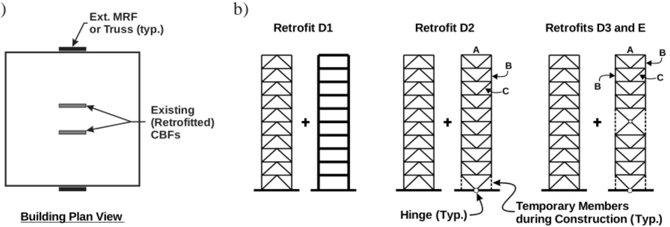
Alternative Retrofit Strategies with Backup External Frames ... 149
6.5 6.5.1 General ... 149 6.5.2 Retrofit D1 ... 150 6.5.3 Retrofits D2 and D3 ... 152 6.5.4 Retrofit E ... 156 Conclusion ... 159 6.6 Acknowledgments ... 161 6.7 References ... 161 6.8 CHAPTER 7 GENERAL DISCUSSION ... 165
Evaluation of existing steel braced frames ... 165
7.1 7.1.1 Impact of the selection of evaluation methods on assessment results ... 165
7.1.2 Influence of selection of selected ground motions in nonlinear dynamic analysis .. 167
7.1.3 Adaption of ASCE 41 linear procedure into Canadian normative context ... 169
7.1.4 Effect of the boundary condition on the seismic evaluation of concentrically braced frames.. ... 169
7.1.6 Connection modelling in braced frames ... 173
7.1.7 Force-delivery reduction factor ... 174
7.1.8 Ductility of steel columns ... 177
Retrofit of existing steel braced frames ... 177
7.2 CHAPTER 8 CONCLUSION AND RECOMMENDATIONS ... 182
Summary and conclusions ... 182
8.1 Recommendations ... 185 8.2 Original contributions ... 185 8.3 BIBLIOGRAPHY ... 187 APPENDICES ... 197
LIST OF TABLES
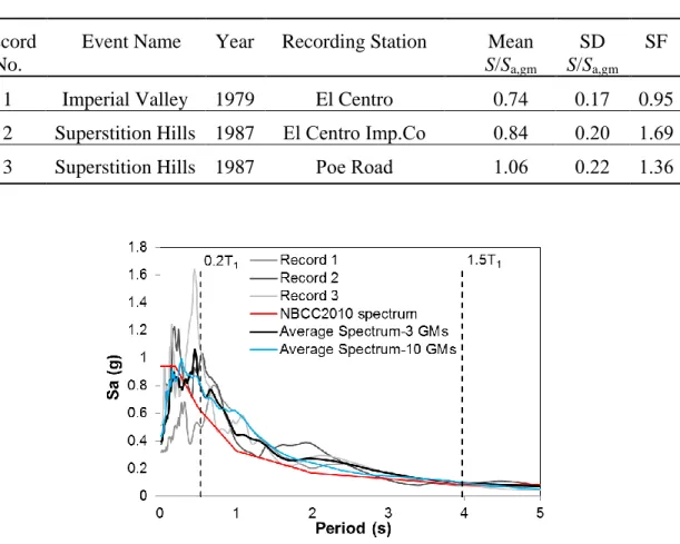
Table 4.1: Characteristics of the three selected ground motion records ... 72
Table 6.1: Brace sections ... 140
Table 6.2: Beam sections ... 140
Table 6.3: Column sections ... 141
Table 6.4: Maximum base shear, maximum overturning moment, steel tonnage, and number of collapse cases ... 145
Table 6.5: Base shear, overturning moment, and roof drift from ASCE 41 NDP ... 152
Table 6.6: Vertical truss members for Retrofits D2 and D3 ... 153
Table A.1: Material properties of coupon testing ... 199
Table A.2: Residual stress measurements determined from individual strips ... 200
Table A.3: Measured dimensions of specimens ... 200
LIST OF FIGURES
Figure 1.1: Brace fracture of NCFB specimen (Sen et al. 2016a). ... 4 Figure 2.1: a) Connection fracture in NCBF 0; and b) Brace hinge formation in NCBF 1 (Johnson
et al. 2014). ... 19 Figure 2.2: a) Connection fracture in NCBF 2; and b) Weld fracture in NCBF 3 (Johnson et al.
2014). ... 20 Figure 2.3: a) Brace fracture in SCBF 1; and b) Bolt hole elongation in the web of the beam of
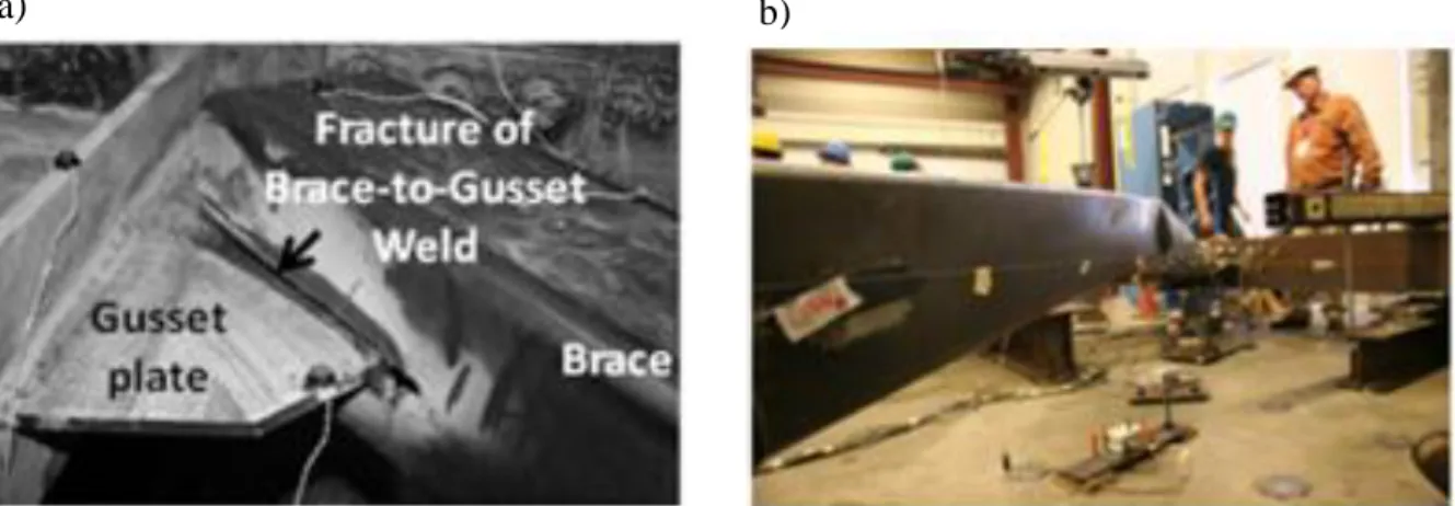
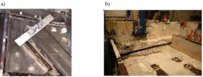
NCBF 4 (Johnson et al. 2014). ... 20 Figure 2.4: a) Brace fracture of first storey brace; and b) Partial fracture of first storey brace-beam gusset plate (Sen et al. 2016a). ... 23 Figure 2.5: a) Out-of-plane deformation of brace; and b) Bottom beam flange yielding and gusset
plate elliptical yielding (Sen et al. 2014). ... 24 Figure 2.6: a) Out-of-plane deformation of wide flange brace; and b) Brace connection fracture at
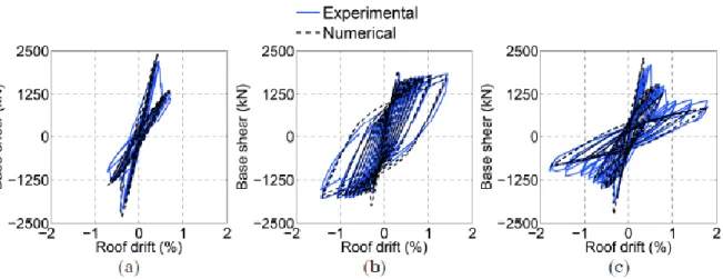
the second level (Sen et al. 2014). ... 25 Figure 2.7: Roof drift-base shear hystereses for a) Specimen 1; b) Specimen 2; and c) Specimen 3
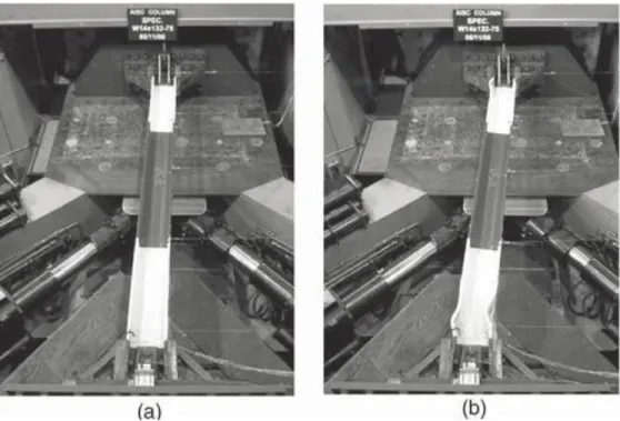
(Sen et al. 2014). ... 31 Figure 2.8: Overall deformed shape of specimen W14x132-75 at a) 4% drift; and b) 10% drift
(Newell and Uang 2008). ... 33 Figure 2.9: Column specimen at the end of test (Lamarche and Tremblay 2011). ... 34 Figure 2.10: Axial load-axial displacement response of the W-shaped column (Lamarche and
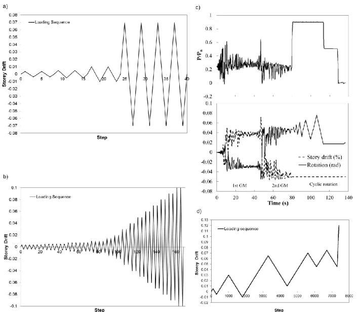
Tremblay 2011). ... 35 Figure 2.11: Failure modes of specimens (Cheng et al. 2013). ... 36 Figure 2.12: Lateral torsional buckling a) south flange view; and b) east view (Zargar et al. 2014). ... 36 Figure 3.1: Dual retrofit options a) location of the external frames; and b) Retrofits D1 to E. ... 45 Figure 3.2: Loading protocol of a) Specimen CS5; b) Specimen CS6; c) Specimen CS7; and d)
Figure 4.1: a) Plan view and braced frame elevations of the building studied; b) Design factored storey shear force per frame; and c) Design factored column axial loads. ... 56 Figure 4.2: NBCC 2010 evaluation of the: a) Braces (YGS = yielding of gross section) and brace
connections (NS = net section failure; BS = block shear failure); b) Beams (CSS = Cross Sectional Strength; OMS = Overall Member Strength); and c) Columns... 59 Figure 4.3: ASCE 41 LDP evaluation of the: a) Bracing members (YGS) and brace connections
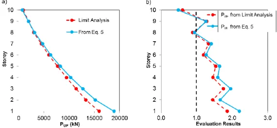
(NS and BS); and b) Beams (CSS and OMS). ... 65 Figure 4.4: ASCE 41 LDP evaluation for the columns: a) Values of PUF; and b) Acceptance
criteria. ... 69 Figure 4.5: NBCC spectrum and 5% damped absolute acceleration spectra of the selected ground
motions. ... 72 Figure 4.6: ASCE 41 NDP evaluation using Model B for the: a) Braces (with structure deformed
shape at t = 13.7 s under record no. 2); b) Beams (CSS, OMS); and c) Columns (LTB = Lateral torsional buckling, LC = LHS column and RC = RHS column). ... 75 Figure 4.7: Response history response using Models B and C: a) Record no. 2; b) Roof
displacements from Models B & C; c) Deformations of LHS braces at levels 8 and 9 from Models B & C; d) Evaluation of the LHS column at level 8 from Model B; e) Evaluation of the LHS column at level 1 from Model B; and f) Axial deformation of the LHS column at level 1 from Model C. ... 79 Figure 4.8: Response and demand for the LHS columns from Model C: a) Axial load-axial
deformation response at level 1; b) P-M interaction at the 1st and 8th levels. ... 79 Figure 4.9: ASCE 41 NDP evaluation of the retrofitted structure using Model C: a) Column
reinforcement; b) Braces; d) Structure deformed shape at t = 13.7 s under record no. 2 with SF = 1.59 and 1.69; d) Axial deformation time history of the LHS brace at level 8 under record no. 2 with SF 1.59 and 1.69; and d) Beams (CSS, OMS). ... 83 Figure 4.10: ASCE 41 NDP evaluation of the retrofitted structure using Model C: a) Columns
based on axial compression only; and b) Columns using current ASCE 41 criteria for axial compression and flexure (LTB = Lateral torsional buckling, LC = LHS column and RC = RHS column). ... 83
Figure 4.11: Column rotation ductility: a) From ASCE 41-13 and finite element analyses; b) Damaged column (case shown: PUF/PCL = 0.5 at θ = 0.22 rad); and c) Moment-rotation
responses from finite element analysis. ... 85 Figure 4.12: Response history response of the LHS column at level 8 from Opensees Model C
and ABAQUS analysis under record no. 2: a) Axial load-rotation response of the column, SF=1.589; b) Moment-rotation response of the column, SF=1.589; c) Axial load-moment response of the column, SF=1.589; d) Axial load-rotation response of the column, SF=1.695; e) Moment-rotation response of the column, SF=1.695; and f) Axial load-moment response of the column, SF=1.695. ... 87 Figure 5.1. Plan view, braced frame elevations and typical connection of the 3- and 10-story
buildings. ... 98 Figure 5.2. NBCC 2010 spectral accelerations for different probabilities of exceedance. ... 99 Figure 5.3. NBCC evaluation results under 60% of NBCC 2010 seismic loads for: a) Braces (BC
= Buckling in compression) and brace connections (NS = net section failure; BS = block shear failure); b) Beams (CSS = Cross Sectional Strength; OMS = Overall Member Strength; ATB = Axial Tension and Bending); and c) Columns. ... 101 Figure 5.4. Axial loads and bending moments in the beam at level 1 of the 10-story frame. (Note:
horizontal loads from floor diaphragms not shown) ... 102
Figure 5.5. NBCC evaluation results under 100% of NBCC 2010 seismic loads: a) Braces (BC = Buckling in compression) and brace connections (NS = net section failure; BS = block shear failure); b) Beams (CSS = Cross Sectional Strength; OMS = Overall Member Strength; ATB = Axial Tension and Bending); and c) Columns. ... 103 Figure 5.6. ASCE 41 linear assessment: a) QUD/QCE ratios of the braces in tension and
compression; b) Assessment of the braces in compression (BC) and brace connections (BS = block shear failure); and c) Assessment of the columns (ULE = Unbalanced Load Effect) for 3-story and 10-story buildings using ASCE LDP (Model A). ... 105 Figure 5.7. Scaling of the selected ground motions for the 10-story building. ... 110 Figure 5.8. Response time history results for the 10-story frame under GM no. H02 from Models
demands in the LHS segment of the beam at level 1; d) Axial and flexural demands in the RHS segment of the beam at level 1; and e) Axial and flexural demands in the RHS column at level 1. ... 113 Figure 5.9. Response time history results from Model D for 3-story frame under GM no. H02 a)
Story drifts; b) Brace axial force demands at level 1; c) Axial and flexural demands in the LHS beam segment at level 1; d) Axial and flexural demands in the RHS beam segment at level 1; and e) Axial and flexural demands in the RHS column at level 1. ... 115 Figure 5.10. a) Finite element modelling of the 2-story chevron braced frame sub-assembly; b)
Responses of the LHS and RHS braces from OpenSees and ABAQUS (LR = Lateral displacement of beam top flange restrained; LTR = Lateral displacement and torsion of beam top flange restrained). ... 118 Figure 5.11. a) Evolution of beam buckling deformed shapes from OpenSees and ABAQUS; and
b) Comparison of LHS and RHS beam buckling response in OpenSees and ABAQUS (LR = Lateral displacement of beam top flange restrained; LTR = Lateral displacement and torsion of beam top flange restrained). ... 119 Figure 5.12. Evaluation of the 10-story frame with retrofitted beams using Model B: a) ASCE 41
NDP evaluation of the braces; b) Story shear demand and capacities from the braces; c) Axial force demands on the columns; and d) LDP evaluation of the columns. ... 121 Figure 5.13. Response time history results from Model B for the 10-story frame with retrofitted
beams under GM no. H02: a) Story drifts; b) Brace axial force demand at level 1; c) Axial and flexural demands in the LHS segment of the beam at level 1; d) Axial and flexural demands in the RHS segment of the beam at level 1; and e) Axial and flexural demands in the RHS column at level 1. ... 123 Figure 6.1. a) Plan view and braced frame elevations of the 10-story building, b) Required cross
section of the beam at the 1st level of the chevron braced frame using ASCE 41-13. ... 135 Figure 6.2.Expected story shear resistances from braces: a) at brace buckling (VCE); and b) from
Figure 6.3. Seismic response of the existing braced frame using models with inelastic braces and: a) Elastic beams and columns; b) Inelastic beams and elastic columns; c) Inelastic beams and columns; and d) Inelastic beams and columns plus gravity columns. ... 136 Figure 6.4. Response time history of existing braced frame with retrofitted beams under GM no.
H02: a) Deformed shape of the frame; b) Roof drift and axial demands in the RHS column at level 1 and LHS column at level 5; c) Axial load-axial deformation response in the RHS column at level 1 and LHS column at level 5; and d) Base shear vs. lateral displacement. 138 Figure 6.5. Retrofits A to D: a) Evaluation of braces using ASCE 41 LDP; and b) Equivalent R-factor. ... 145 Figure 6.6. Deformed shape near collapse for Retrofits A to D under GM no. H05 ... 146 Figure 6.7. Response time history of Retrofit A under GM no. H05: a) Story drifts; b) Brace
axial force demand at level 1; c) Axial and flexural demands in the LHS column at level 1; d) Axial and flexural demands in the RHS column at level 1; and e) Axial and flexural demands in the beam at level 1. ... 147 Figure 6.8. Dual system retrofit options: a) location of the external frames; and b) Retrofits D1 to
E. ... 150 Figure 6.9. Evaluation of the Retrofit D braced frame in Retrofit D1: a) NDP evaluation of the
braces; b) LDP evaluation of the beams; and c) LDP evaluation of the columns. ... 151 Figure 6.10. Evaluation of Retrofit D2: a) DCR of selected truss members; and b) NDP evaluation
of the braces. ... 154 Figure 6.11. Evaluation of Retrofit D3: a) DCR of selected truss members; b) NDP evaluation of
the braces; c) LDP evaluation of the braced frame beams; and d) LDP evaluation of the braced frame columns. ... 155 Figure 6.12. Evaluation of Retrofit E: a) ASCE 41 NDP evaluation of the braces; b) LDP
evaluation of the columns; c) LDP evaluation of the beams; and d) Axial load-axial deformation response for the RHS beam at level 2 under GM no. H01. ... 158 Figure 7.1: Overview of specimen (Sen et al. 2016a). ... 172 Figure 7.2: Failure in brace connection (Tremblay et al. 2012). ... 174
Figure 7.3: Axial force demands induced on the columns of tension-only X-braced frame. ... 176 Figure 7.4: Axial force demands on the columns of chevron braced frame. ... 176 Figure 7.5: Reduced Beam Section (RBS) Connection (CISC 2008). ... 181 Figure A.1: Components of Multi-Directional Hybrid Testing System (Imanpour 2015). ... 198 Figure A.2: Shop drawing of specimen CS5. ... 201 Figure A.3: Applied loading protocol to specimen CS5. ... 202 Figure A.4: Deformed shape of specimen CS5 at a) 0.375%; and b) 0.50% storey drift. ... 202 Figure A.5: Deformed shape of specimen CS5 at a) first peak +7.0%; b) second peak -7.0%; and
c) third peak +7.0% storey drift. ... 203 Figure A.6: Specimen CS5 at a) column buckling; and b) local buckling at bottom and top of
specimen. ... 204 Figure A.7: Normalized flexural strength response versus storey drift of specimen CS5 with and
without presence of friction forces. ... 204 Figure A.8: a) Axial shortening; b) rotation; and c) axial load of specimen CS5. ... 205 Figure A.9: Strain gauge measurements at top and middle of specimen CS5: a) G1, G2, G7, G8
(top); b) G3, G4, G5, G6 (top); c) G1, G2, G7, G8 (middle); and d) G3, G4, G5, G6 (middle). ... 206 Figure A.10: Shop drawing of specimen CS6. ... 207 Figure A.11: Applied loading protocol to specimen CS6. ... 208 Figure A.12: Deformed shape of specimen CS6 at a) 0.375%; b) 0.5%; c) 0.75%; and d) 1%
storey drift. ... 208 Figure A.13: Specimen CS6 at a) column buckling; and b) local buckling at bottom, middle and
top of specimen. ... 209 Figure A.14: Normalized flexural strength response versus storey drift of specimen CS6 with and
without presence of friction forces. ... 210 Figure A.15: a) Axial shortening; b) rotation; and c) axial load of specimen CS6. ... 210
Figure A.16: Strain gauge measurements at top, middle and bottom of specimen CS6: a) G1, G2, G7, G8 (top); b) G3, G4, G5, G6 (top); c) G1, G2, G7, G8 (middle); d) G3, G4, G5, G6 (middle); e) G1, G2, G7, G8 (bottom); and f) G3, G4, G5, G6 (bottom). ... 211 Figure A.17: Shop drawing of specimen CS7. ... 212 Figure A.18: a) Applied axial load, story drift and top end rotation; b) Top end moment about
strong axis and axial shortening vs top end rotation; and c) Buckled shape at the end of the test. ... 214 Figure A.19: Deformed shape of specimen CS7 under the first imposed ground motion at a) 1-10
sec; b) 10-20 sec; c) 20-30 sec; and d) 30-40 sec. ... 215 Figure A.20: Deformed shape of specimen CS7 under the second imposed ground motion at a) 1-10 sec; b) 1-10-20 sec; c) 20-30 sec; and d) 30-40 sec. ... 215 Figure A.21: Deformed shape of specimen CS7 at a) 0.9 PCL; b) 0.5% rad; c) 1% rad; d) 1.5%
rad; e) 2% rad; and f) 3% rad. ... 216 Figure A.22: Local buckling of specimen CS7 at a) bottom; b) middle; and c) top of column. .. 217 Figure A.23: Axial shortening of specimen CS7. ... 217 Figure A.24: Strain gauge measurements at top, middle and bottom of specimen CS7: a) G1, G2,
G7, G8 (top); b) G3, G4, G5, G6 (top); c) G1, G2, G7, G8 (middle); d) G3, G4, G5, G6 (middle); e) G1, G2, G7, G8 (bottom); and f) G3, G4, G5, G6 (bottom). ... 218 Figure A.25: Lateral displacement imposed to Specimen CS10. ... 219 Figure A.26: Specimen CS10 a) normalized axial strength response versus storey drift; and b)
normalized flexural strength response versus storey drift. ... 220 Figure A.27: Deformed shape of specimen CS10 at a) 0.03; b) -0.01; c) 0.065; and d) 0.01 storey
drift. ... 221 Figure A.28: Deformed shape of specimen CS10 at a) 0.07; b) 0.045; c) 0.075; and d) 0.045
storey drift. ... 221 Figure A.29: Deformed shape of specimen CS10 at buckling a) web view; and b) flange view. 222 Figure A.30: a) Axial shortening; and b) rotation of specimen CS10. ... 222
Figure A.31: Strain gauge measurements at top, middle and bottom of specimen CS10: a) G1, G2, G7, G8 (top); b) G3, G4, G5, G6 (top); c) G1, G2, G7, G8 (middle); d) G3, G4, G5, G6 (middle); e) G1, G2, G7, G8 (bottom); and f) G3, G4, G5, G6 (bottom). ... 223 Figure B.1: Details of modelling of the brace and brace connection. ... 227 Figure B.2: Hysteretic responses of double angle bracing members: a) comparison between
models with single and two individual elements; b) Influence of the stitch connector on brace axial response. ... 228 Figure B.3: a) In-plane deformation; and b) out-of-plane deformation of the brace with one stitch
at the mid-length of member. ... 230 Figure B.4: Axial load-axial deformation response of the column. ... 230 Figure B.5: a) Models used for examination of the beam buckling response at the 1st level of
chevron braced frame; and b) computed beam axial load-deformation responses. ... 232 Figure B.6: a) Moment-storey drift response of the column; and b) normalized bending demand
to Mu. ... 233 Figure B.7: a) Stress demand; and b) strain demand at the left and right corners of the column
cross section. ... 234 Figure B.8: Applied loads to the chevron braced frame. ... 235 Figure B.9: Block shear failure of a bolted gusset plate (Singh Huns et al. 2002). ... 237 Figure C.1: Details of column modelling. ... 239 Figure C.2: Applied axial load to the existing and retrofitted column a) in tension; b) in
compression; and c) Difference of column axial load using the existed and retrofitted cross sections. ... 251
LIST OF SYMBOLS AND ABBREVIATIONS
Symbols
A Design acceleration ratio, cross-section area
Ag Gross area
Agv Gross area in shear for block failure
An Critical net area
Anv Effective net area reduced for shear lag
Cr Factored compressive resistance of a member
C1 Modification factor to relate expected maximum inelastic displacements to displacements calculated for linear elastic response
C2 Modification factor to represent the effects of pinched hysteresis shape, cyclic stiffness degradation and strength deterioration on the maximum displacement response
Cr Factored compressive resistance of a member
D Dimension of the building in a direction parallel to the applied forces, Dead load E Earthquake load, Young’s modulus of elasticity
F Foundation factor
Fa Acceleration-based site coefficient
Ft Portion of V to be concentrated at the top of the structure
Fu Specified minimum tensile strength
Fue Expected tensile strength
Fv Velocity-based site coefficient
Fy Specified minimum yield stress
Fye Expected yield strength
IE Earthquake importance factor of the structure
J Force-delivery reduction factor
JBase Numerical reduction coefficient for base overturning moment
K Coefficient that reflects the material and type of construction, effective length factor
L Live load, length
MCEx Expected bending strength of a member about the x-axis
MCEy Expected bending strength of a member about the y-axis
MCLx Lower-bound flexural strength of the member about the x-axis
MCLy Lower-bound flexural strength of the member about the y-axis
Mr Factored moment resistance of a member
MUFx Bending moment in the member about the x-axis
MUFy Bending moment in the member about the y-axis
Mv Factor to account for higher mode effect on base shear
Mx Bending moment in a member for the x-axis
My Bending moment in a member for the y-axis
PCE Expected compressive strength of the brace
PCL Lower-bound axial strength of a column
Pe Euler buckling strength
PGi Axial load in the column at level i due to gravity loading
PUF Design axial force in a member
Py Axial load causing yield over the whole section
Pye Member expected yield axial strength
QCE Expected strength of a deformation controlled action of an element at the
deformation level under consideration
QCL Lower-bound estimate of the strength of a force-controlled action of an element at
the deformation level under consideration
QE Action caused by the response to selected Seismic Hazard Level
QG Action caused by gravity loads
QUD Deformation-controlled action caused by gravity loads and earthquake forces
QUF Force-controlled action caused by gravity loads and earthquake forces
R Force modification factor
Rd Ductility-related force modification factor Ro Overstrength-related force modification factor
S Seismic response factor
S(Ta) Design spectral response acceleration for a period of Ta
Sa(0.2) 5% damped spectral response acceleration, expressed as a ratio to gravitational
acceleration, for a period of 0.2 seconds
Sa(1.0) 5% damped spectral response acceleration, expressed as a ratio to gravitational
acceleration, for a period of 1.0 second
S/Sa,gm Ratio between the NBCC and ground motion spectra
T Fundamental period of the structure
Ta Fundamental lateral period of the structure in the direction under consideration
TCE Expected tensile strength of the brace
Tr Factored tensile resistance of a member
T1 Computed period from dynamic analysis
U1 Factor to account for moment gradient and for second-order effects of axial force
acting on the deformed member
V Minimum lateral seismic force at the base of the structure, Lateral earthquake design force at the base of the structure
Vp Plastic shear resistance of the beam
W Seismic weight
Z Plastic section modulus
b Flange width
h Web width
hn Building height
m Component demand modification factor to account for expected ductility associated with this action at the selected Structural Performance Level
mx Value of m for bending about the x-axis of a member
my Value of m for bending about the y-axis of a member
ry Radius of gyration of a member about its weak axis
t Flange thickness
tkp Thickness of the knife plate
tp Thickness of the gusset plate
tw Web thickness
w Web thickness
β Coefficient for weak axis bending in beam-columns
Δt Axial deformation at expected tensile yield strength
δavg The average of displacements at the extreme points of the diaphragm at level x
δmax The maximum displacement at any point of the diaphragm at level x
ϕ Resistance factor
ω1 Coefficient to determine equivalent uniform bending effect in beam-columns θp Plastic rotation
θy Yield rotation
Abbreviations
ASCE American society of civil engineers BRB Buckling-restrained brace
BS Block shear
BSE-1E Basic safety earthquake-1 for use with the basic performance objective for existing buildings
BSE-2E Basic safety earthquake-2 for use with the basic performance objective for existing buildings
CBF Concentrically braced frame CC Conventional construction CSS Cross-section strength DBF Ductile braced frame DCR Demand-capacity ratio EBF Eccentrically braced frame ESFP Equivalent static force procedure
IP In-plane
HSS Hollow structural sections LDP Linear dynamic procedure LSP Linear static procedure LTB Lateral torsional buckling
NBCC National Building Code of Canada NCBF Non-seismic concentrically braced frame NDBF Nominal ductility braced frame
NDP Nonlinear dynamic procedure
NS Net section
NSP Nonlinear static procedure OMS Overall member strength OOP Out-of-plane
OpenSees Open system for earthquake engineering simulation RBS Reduced beam sections
RSA Response spectrum analysis
SCBF Special concentrically braced frame SD Standard deviation
SF Scale factor
UFM Uniform force method UHS Uniform hazard spectral YGS Yielding on gross section
LIST OF APPENDICES
APPENDIX A – experimental study of steel columns ... 197 APPENDIX B – Modelling ... 224 APPENDIX C – update the cross section of a member in opensees ... 238
CHAPTER 1
INTRODUCTION
Background
1.1
New steel buildings designed in accordance with the seismic provisions of the National Building Code of Canada (NBCC) (NRCC 2010) and the steel structures design standard CSA S16 (CSA 2009) are conceived to safely resist seismic loads and develop sufficient ductility while maintaining adequate strength and stiffness. However, it was only in 1989 that the special seismic design and detailing requirements for steel structures were introduced in the CSA S16 standard (Redwood and Channagiri 1991, Mitchell et al. 2010). Thus, it is likely that the buildings designed prior to 1990’s do not develop the desired ductile response under seismic loads. In the 1980’s, concentrically braced frames with tension-only X-bracing and chevron bracing were commonly used to resist lateral loads in steel buildings in Canada. Back-to-back double angles were used for braces, whereas W sections were usually selected for beams and columns. Braces were connected to gusset plates by bolts, often arranged in a single bolt line or in double row bolt configurations, if angles with wider legs were used. Chevron-type brace frames have been particularly popular, both in Canada and in U.S. because of their structural efficiency and architectural flexibility. Aging buildings with concentrically braced frames represent a large percentage of existing steel building stock in Canada and U.S., and have potential to increase significantly the seismic risk in large cities. It is therefore essential to properly asses the seismic behaviour of such buildings and put forward cost-efficient retrofit solutions if deemed necessary. Several experimental and numerical studies have been carried out in U.S. to investigate the seismic behaviour of existing concentrically braced frames with limited ductility named non-ductile concentrically braced frames (NCBF) (Goel 1992, Johnson et al. 2014, Sloat 2014, Hsiao 2014, Sen et al. 2016a). These studies confirmed the likelihood of seismic deficiencies associated with non-compact brace sections, excessive brace slenderness and non-ductile failure modes in connections. Typical brace fracture observed in the experiments conducted on NCBFs is shown in Figure 1.1. Khatib et al. (1998) studied the seismic response of chevron-type NCBFs and concluded that, in addition to potential braces and brace connections problems, beams may be prone to develop plastic hinging because of the insufficient resistance caused by a substantial
difference between the new and old seismic design procedures. This behaviour can lead to soft-story response and compromise the system gravity load resisting capacity.
The principal document for seismic evaluation and the retrofit of existing building in U.S. is the ASCE 41-13 standard (ASCE 2013). It is the combination of former U.S. national standards for seismic evaluation (ASCE 31-03) and seismic retrofit (ASCE 41-06). The evaluation and retrofit process begins with the selection of the appropriate performance objectives to maximize benefits (e.g. improved safety or reduction of damage and downtime periods) while considering the cost and feasibility. Performance objective defines the desired structural and non-structural performances and the specific levels of seismic hazard. A three-tiered evaluation procedure is proposed including Tier 1: screening, Tier 2: deficiency-based evaluation, and Tier 3: systematic evaluation. In Tier 3, seismic demand is evaluated from structural analysis and the evaluation is performed at the components level by verifying acceptance criteria reflecting the expected capacity of the components.
Unlike the U.S., where the state-of-the-art documents for the evaluation and retrofit of the existing structures are available, in Canada the sources are rather limited. NBCC 2010 defines the seismic load to be used for the initial assessment: 60% of earthquake loads prescribed for new buildings that are established for a probability of exceedance of 2% in 50 years. If the deficiencies are identified for this load level, the retrofit is required and should be designed for higher seismic forces, preferably meeting the performance objective for new buildings, i.e. collapse prevention for a seismic hazard with probability of exceedance of 2% in 50 years. Future building use, control of seismic damage and the differential in upgrading costs with force levels can justify the use of lower seismic loads (Allen et al. 1992). The Code de construction du Québec (Code de construction 2015), addresses specifically the existing buildings designed in accordance with the 1990 or earlier edition of the NBCC. It is specified in this document that if the building’s seismic force resisting system is modified, the seismic weight is increased by more than 5% or the intervention affects more than 25% of the total floor area for post-disaster buildings, the seismic lateral resistance should be increased to a minimum of 60% of the level prescribed in NBCC 2005 (NRCC 2005). More information about the levels of seismic loads, analysis procedures and acceptance criteria for seismic evaluations is provided in NRC Guidelines for the seismic evaluation of existing buildings (Allen et al. 1992). Information is also available for retrofit of existing buildings (Allen et al. 1995) and rapid screening techniques
(NRC 1993). However, all documents are based on old U.S. guidelines (ATC-14 1987, ATC-22 1989, FEMA 1992a, FEMA 1992b) and 1990 edition of NBCC and are no longer up-to-date. In 2013, a procedure for rapid screening of existing buildings has been updated to reflect NBCC2010 provisions but other documents remained unchanged (Saatcioglu et al. 2013).
In the absence of comprehensive Canadian guidelines for seismic evaluation of existing buildings, the application of the Tier 3 ASCE 41 procedure can be used to explore the potential for savings using specific provisions for seismic assessment and retrofit of existing buildings. In such case, the procedures and the acceptance criteria need to be adapted to Canadian normative context. Certain assumptions, which are currently in use in ASCE 41 seem conservative and need a critical review. For example, presently it is required that the beams of chevron braced frames be evaluated as force-controlled (non-ductile) components. In more recent experimental studies, Sen et al. (2016) argued that the flexural yielding of the beams can, in fact, provide additional energy dissipation mechanism, and eventually reduce retrofit costs. Accepting ductility which can develop through beam flexural yielding would have a favorable impact on the extent of required retrofit in such structures and thereby reduce its cost. However, before this concept can be widely applied, further studies are needed to investigate the impact of such behaviour on system response. The past studies did not address behaviour of frames with beams that have small tributary gravity loading. Such light beams may fail by instability prior to developing ductile flexural yielding, with detrimental consequences on frame response. Therefore, it is necessary to investigate this more critical failure mode to establish the limits on acceptable beam demand-to-capacity ratios. Similarly, establishing more precisely the relationship between the flexural ductility that can develop in columns and their axial load would increase the instances when the flexural action could be considered as deformation-controlled, and this in turn would have a beneficial impact on assessment results. Present ASCE 41-13 requirements for steel columns are rather conservative compared to the experimental evidences and could be relaxed. The study conducted by Bech et al. (2015) confirmed the potential that columns develop flexural ductility for levels of axial load higher than the ones presently considered. However, further numerical and experimental studies are required before such modifications could be safely incorporated into codified assessment procedures.
Figure 1.1: Brace fracture of NCFB specimen (Sen et al. 2016a).
Objectives
1.2
The general objectives of this Ph. D. thesis are:
– Evaluate the seismic performance of multi-storey concentrically braced frames with focus on tension-only and chevron braced frames to identify the deficiencies of these systems and compare the assessment results obtained from NBCC 2010 and ASCE 41-13 evaluation methods. The evaluation should include an explicit verification of yielding and buckling limit states for the main structural components (braces, beams and columns) and examine the global stability performance of braced frames.
– Examine the possibility of allowing flexural yielding in beams of chevron braced frames with consideration of the anticipated high compression force demand.
– Assess the appropriateness of current ASCE 41 acceptance criteria for braced frame columns subjected the high axial compression combined with drift induced flexural demand and/or plastic rotations.
– Propose retrofit solutions using ASCE 41-13 procedures to improve the seismic response of a seismically deficient multi-storey chevron braced frame.
Research methodology
1.3
The research methodology that was adopted can be summarized as follows:
– A literature review was carried out on the evaluation and retrofit of existing concentrically braced frames (CBFs), including the documents currently used in Canada and the U.S. for the seismic evaluation of buildings. The provisions of the 1980 NBCC (NRCC 1980) and CSA-S16.1-M78 (CSA 1978) steel design standard to be used for the design of prototype structures were also studied.
– The following tasks were performed to achieve the first objective:
A prototype 10-storey building with tension-only X-braced frames in one direction and tension-compression chevron braced frames in other direction was designed in accordance with the provisions of the 1980 NBCC and CSA-S16.1-M78 steel design standard. The same building with only three storeys and chevron braced frames was also examined. Both buildings were assumed to be located on a site class C in Vancouver, British Columbia. Seismic conditions in Vancouver are similar to those that prevail in north western U.S. and the site was chosen so that the results could also apply to this region.
Seismic evaluation of the structures was carried out using the approach proposed in the 2010 NBCC and the ASCE 41-13. For the former, the evaluation was performed using linear analysis under 60% and 100% of the NBCC 2010 seismic loads. Seismic loads in the NBCC are specified for a probability of exceedance of 2% in 50 years and the target performance is collapse prevention. Seismic evaluation results under 60% NBCC seismic loads are used to determine if the retrofit is needed. For ASCE 41, a Tier 3 evaluation using linear and nonlinear dynamic analysis procedures (LDP and NDP) was performed to verify collapse prevention performance under a seismic hazard corresponding to a probability of exceedance of 2% in 50 years, i.e. same as in the NBCC to allow a direct comparison.
For the ASCE 41 assessment, the influence of the seismic hazard level was investigated by also considering probabilities of exceedance 5% in 50 years and 10% in 50 years for the evaluation of both chevron braced frames using the nonlinear dynamic procedure.
Linear analysis was performed using commercially available structural analysis programs. For nonlinear dynamic analysis, the concentrically braced steel frames were modelled in
OpenSees finite element structural analysis platform (McKenna and Fenves, 2004). Different
models were employed to examine the effect of nonlinearity on structural members. A set of 10 ground motion records was used to evaluate the seismic performance of the concentrically braced frames. Attention was paid in the model to properly simulate instability limit states at the local (member) and global (frame) levels.
Column axial forces for ASCE 41 LDP assessment were determined using two scenarios including the application of the force-delivery reduction factor and limit-state analysis both specified in ASCE 41. This comparison was used to determine the appropriateness of the force-delivery reduction factor to predict the loads in force-controlled members.
– For the second objective, the following tasks were performed:
A comprehensive study of the beam flexural and stability response in the 10-storey chevron braced frame was conducted using five different types of modelling in the OpenSees program.
The results from OpenSees simulations were validated by means of a detailed 3D finite element analysis of the beam and braces of the first two levels using the ABAQUS software (Dassault 2012). The FE model accounted for inelastic response of the braces and beams. For the beams, flexural yielding as well as in-plane and out-of-plane buckling could be predicted, including the restraint offered by the floor slabs.
– For the third objective, the following tasks were performed:
Comprehensive 3D finite element analysis in ABAQUS was performed for individual columns of the 10-storey tension-only braced frame. This analysis technique was used because the OpenSees program can not predict local buckling effects on the column flexural strength and ductility and the flexural-torsional buckling limit states. In the analyses, the columns were initially subjected to different levels of axial loads varying from 0.1 to 0.9 times their lower-bound axial compressive strength, and the storey drift was monotonically increased until stability failure of the columns occurred. The results obtained from both OpenSees and ABAQUS programs were compared, and the effect of local buckling on the
column flexural strength was examined. The results were used to evaluate the appropriateness of the current ASCE 41 limits for steel columns subjected to axial compression and flexure.
An extensive experimental program was performed on four full-scale W-shaped columns using the Multi-Directional Hybrid Testing System (MDHTS) of the Structural Engineering Laboratory at Polytechnique Montréal. The tests aimed at investigating the plastic rotation capacity of the columns and their buckling response. The test results were used to validate the analysis results from the OpenSees and ABAQUS numerical simulations. The results were also considered to assess the ASCE 41 limits for steel columns subjected to axial compression and flexure.
– For the fourth objective, the following tasks were performed:
Different retrofit solutions were examined for the 10-storey chevron braced frame. Various approaches were investigated to replace the braces with the main objectives of minimizing the force demand on beams, columns, and foundations while achieving uniform demand to capacity ratios along the frame height to avoid soft-story response.
Two dual frame options were considered, one by adding back-up steel moment frames and one by adding stiff vertical elastic trusses acting as vertical spines. Both additional systems were placed on the perimeter of the building and acted in parallel with the retrofitted chevron braced frames with retrofitted beams and braces. Two configurations were considered for the stiff vertical elastic trusses: continuous trusses over the full building height and trusses with a hinge at the mid-height. The latter was also used in combination with the existing chevron braced frames with reinforced columns only.
The effectiveness of all retrofit scenarios was assessed by comparing the required steel tonnage and anticipated base reactions to those obtained with new reference chevron braced frames designed in accordance with current Canadian seismic design provisions.
Organization
1.4
This dissertation consists of 8 chapters and three appendices. In Chapter 1 the motivation for the study is discussed, the main objectives of the research are defined and the applied methodology is
described. Chapter 2 presents the literature review on the seismic evaluation and retrofit of existing concentrically braced frames and seismic behaviour of steel columns. A detailed description of the methodology applied in this research is described in Chapter 3. Chapters 4 to 6 describe 3 articles that present the main tasks performed in this research and the main findings of the research. The three articles, which have been submitted for publication in scientific journals, are:
1) Balazadeh-Minouei, Y., Koboevic, S., and Tremblay, R. 2017. Seismic Evaluation of a Steel Braced Frame using NBCC and ASCE 41. Journal of Constructional Steel Research. http://dx.doi.org/10.1016/j.jcsr.2017.03.017.
2) Balazadeh-Minouei, Y., Koboevic, S., and Tremblay, R. 2017. Seismic Assessment of Existing Steel Chevron Braced Frames. Submitted to the Journal of Structural Engineering, ASCE on February 6, 2017 (initial version) and June 12, 2017 (revised version).
3) Balazadeh-Minouei, Y., Tremblay, R., and Koboevic, S. 2017. Seismic Retrofit of an Existing 10-Story Chevron Braced Steel Frame. Submitted to the Journal of Structural Engineering, ASCE on July 14, 2017.
Chapter 7 presents a general discussion of results, while the summary of the project, the main conclusions as well as the recommendations for future studies is described in Chapter 8. In Appendix A, the experimental study of steel columns is explained. Appendix B presents the details of modelling using OpenSees and ABAQUS. Appendix C describes the updating of a cross section modelled in OpenSees.