UNIVERSITÉ DE MONTRÉAL
NUMERICAL AND EXPERIMENTAL SEISMIC ASSESSMENT AND RETROFIT OF STEEL TENSION-ONLY DOUBLE ANGLE BRACED FRAMES DESIGNED BEFORE THE
IMPLEMENTATION OF DETAILING PROVISIONS FOR DUCTILE SEISMIC RESPONSE
YAN JIANG
DÉPARTEMENT DES GÉNIES CIVIL, GÉOLOGIQUE ET DES MINES ÉCOLE POLYTECHNIQUE DE MONTRÉAL
MÉMOIRE PRÉSENTÉ EN VUE DE L’OBTENTION DU DIPLÔME DE MAÎTRISE ÈS SCIENCES APPLIQUÉES
(GÉNIE CIVIL) AVRIL 2013
UNIVERSITÉ DE MONTRÉAL
ÉCOLE POLYTECHNIQUE DE MONTRÉAL
Ce mémoire intitulé:
NUMERICAL AND EXPERIMENTAL SEISMIC ASSESSMENT AND RETROFIT OF STEEL TENSION-ONLY DOUBLE ANGLE BRACED FRAMES DESIGNED BEFORE THE
IMPLEMENTATION OF DETAILING PROVISIONS FOR DUCTILE SEISMIC RESPONSE
présenté par : JIANG Yan
en vue de l’obtention du diplôme de : Maîtrise ès sciences appliquées a été dûment accepté par le jury constitué de :
Mme KOBOEVIC Sanda, Ph.D., présidente
M. TREMBLAY Robert, Ph.D., membre et directeur de recherche Mme TIRCA Lucia, Ph.D., membre et codirectrice de recherche M. LIGNOS Dimitrios, Ph.D., membre
______________________
ACKNOWLEDGEMENTS
Completion of this research project at École Polytechnique of Montréal is inseparable from the help and support of many people, I would like to thank.
First, I want to express my sincere and deepest gratitude to my supervisor Professor Robert Tremblay and co-supervisor Professor Lucia Tirca for their continued encouragement and their expert guidance. Their help and support for this research project will never be forgotten.
I would like to present my special thanks to Professor Ali Davaran for his assistance in the development of the numerical model of the bracing member, and Martin Leclerc who was involved directly on preparation of hybrid test setups. My sincere appreciation also go to Marc Charbonneau, Patrice Bélanger, David EK, Guillaume Cossette, Xavier Willem and Cédric Androuet at the Structures Laboratory of École Polytechnique of Montréal for their invaluable assistance.
I wish to thank the external jury, Professor Sanda Koboevic from École Polytechnique of Montréal and Professor Dimitrios Lignos from Mcgill University to have read and evaluated this Master Thesis.
Funding from the Canadian Seismic Research Network (CSRN) of the Natural Sciences and Engineering Research Council (NSERC) of Canada and the Strategic Network Program of the Fonds Québécois pour la Recherche sur la Nature et les Technologies (FQRNT) is acknowledged. It was a pleasure to shear this wonderful time with all my colleagues and friends in Polytechnique. Finally, I would like to thank to my dear wife and parents for their unconditional love, support and trust.
RÉSUMÉ
Au Canada, une proportion importante des bâtiments en acier de faible hauteur ont été conçus et construits avant l'introduction, en 1989, des normes de conception parasismique dans la norme pour la conception des structures en acier. Il est donc probable que l'évaluation de ces structures sur la base des codes en vigueur, révèle des déficiences quant à leur capacité de résister adéquatement aux effets des tremblements de terre. Il est donc nécessaire de développer des méthodes efficaces et facilement applicables pour l’évaluation et la réhabilitation sismiques de ces structures de bâtiments.
Dans cette étude, on se concentre sur l'évaluation et la réhabilitation sismique des contrenventements en acier de type tension-seulement, construits avec des diagonales faites de deux cornières assemblées entre elles, qui ont été largement utilisés au Canada pour la résistance aux charge latérales dans les bâtiments de faible hauteur. Ces structures sont encore populaires aujourd'hui.
Un bâtiment prototype de 4 étages de hauteur avec contenvetements en tension-seulement a été conçu conformément aux codes et critères en vigueur au début des années 1980. La structure est localisée sur un sol ferme à Vancouver, Colombie-Britannique. Les diagonales des contreventements sont formées de cornières assemblées dos-à-dos avec des assemblages boulonnés aux extrémités. L'évaluation de l'un des contreventements a été effectué conformément au Code national du bâtiment du Canada 2010 et à la norme CSA S16-09 pour les structures en acier. Les résultats montrent que certaines des diagonales de contreventement, que tous les assemblages des diagonales de contreventement et que certains des poteaux avaient une résistance insuffisante. Cette déficience était plus marquée pour les assemblages des diagonales compte tenu qu'un calcul par capacité visant à établir un ordonnancement de la plastification et un comportement ductile des diagonales n'avait pas été considéré pour leur conception. Compte tenu de ce constat et de la ductilité limitée associée aux modes de rupture dans les assemblages, on s'est concentré dans ce projet sur l'évaluation du comportement sismique des assemblages des diagonales et au développement et à la validation de méthodes de réhabilitation permettant d'éviter la rupture fragile des assemblages et l'effondrement des structures pouvant en découler.
Un programme d'essais cyclique quasi-statique a été réalisé sur des spécimens à varaie grandeur de diagonales faites de cornières dos-à-dos et de leurs assemblages d'extrémité pour confirmer les
déficiences qui avaient été identifiées par calculs et valider les méthodes de réhabilitation. Comme prévu, les essais ont démontré qu'une ductilité plus élevée pouvait être atteinte dans un système diagonale-assemblage lorsque les déformations inélastiques se développaient principalement dans l'aire brute des diagonales. Malgré qu'elle était limitée, la rupture dans un assemblage des diagonales pouvait cependant offrir un certain niveau de ductilité. La répartition de la sollicitation inélastique entre les diagonales et les assemblages dépend principalement de leur résistance relative et, par conséquent, des propriétés mécaniques de l'acier des composantes. La capacité de prédire le comportement dépend donc fortement de la précision des équations utilisées pour évaluer la résistance associée aux divers états limites et de la connaissance des propriétés réelles des matériaux. Dans la présente étude, par exemple, on a noté que les équations pour déterminer la résistance en traction sur l'aire nette étaient du côté de la sécurité et que la limite élastique de l’acier des diagonales étaient plus faible que la valeur probable utilisée dans les calculs, ce qui a eu comme effet de produire des déformations inélastiques plus importantes dans la diagonale et une ductilité plus élevée que prévues. On a aussi observé que l'écrouissage de l'acier pouvait aussi contribuer à favoriser les déformations inélastiques entre les composantes.
L'adéquation d'une technique de réhabilitation sismique dépend aussi fortement de la capacité de prédire la résistance relative des différents modes de rupture le long du cheminement des efforts. Les essais ont démontré que la stratégie de réhabilitation la plus prometteuse parmi celles qui ont été examinées dans cette étude est celle où on introduit des trous oblongs pour former des fusibles ductiles parallèles dans les goussets d'asssemblage, entre les diagonales et les poutres ou poteaux. Le système offre un comportement inélastique présivisible qui permet d'augmenter la ductilité de l'assemblage out en controllant les forces induites dans le système.
Les connaissances acquises et les résultats obtenus dans les essais ont permis de développer et de valider un modèle numérique pour la diagonales de contreventement faites de deux cornières assemblées. Le modèle tient compte de l'influence des contraintes résiduelles, des défauts de rectitude et de la stabilité des cornières individuelles et combinées sur le flambement de la diagonale. Le comportement en flexion, les déformations axiales inélastiques et la rupture des diagonales ont aussi été incorporées dans le modèle. Des simulations hybrides ont été réalisées pour vérifier la possibilité de prédire le comportement inélastique des diagonales, incluant la rupture des assemblages et leurs conséquences sur la résistance à l'effondrement des structures. Ce
travail présentait un défi particulier en raison du caractère peu ductile de la rupture des assemblages et du fait qu'il s'agissait d'une première série de simulations hybrides réalisées à l'École Polytechnique avec les applications OpenSees/OpenFresco. Les simulations ont par conséquent été réalisées avec un model simplifié de la structure prototype. Une bonne corrélation a été obtenue entre les simulations purement numériques et les simulations hybrides.
Dans la dernière phase de la recherche, on a réalisé des analyses dynamiques temporelles non linéaires de grande envergure pour évaluer la résistance contre l'effondrement de la structure prototype. Un modèle numérique détaillé a été utilisé à cette fin. Ce modèle comprenait le système de résistance aux charges de gravité, incluant le comportement non-linéaire des assemblages entre les poutres et les poteaux. La structure a été évaluée dans les conditions originale et réhabilitée. Les analyses ont montré que la structure originale devait être réhabilitée pour atteindre les niveaux de fiabilité minimum requis contre les séismes. En dépit des avantages, la technique de réhabilitation avec des trous oblongs percés dans les goussets n'a pas permis n'obtenir le niveau de fiabilité requis.
ABSTRACT
In Canada, a large portion of low-rise steel buildings were designed and built before the implementation of the first provision of seismic design and detailing introduced in steel structure design standard in 1989. It is therefore likely that an assessment of these structures based on current seismic design requirements reveals the deficiencies that may affect the ability of these structures to properly withstand earthquake effects. Hence, an efficient and convenient method to seismically assess and retrofit these buildings is necessary.
This study focuses on the seismic assessment and retrofit of steel tension-only braced frames built with double angle braces, a seismic force resisting system (SFRS) that has been extensively used for low-rise building structures. The system is still popular today. In this study, a 4-storey prototype steel building structure with tension-only braced frame was designed according to the design regulations applicable in the early 1980's. The structure was assumed to be located on a firm ground site in Vancouver, British Columbia. The bracing members were back-to-back double angle sections with bolted end connections. Seismic assessment of one braced frame was performed using the current design requirements and design equations of the National Building Code of Canada 2010 and the CSA S16-09 steel design standard. It was found that some of the bracing members, all bracing member connections and some of the columns had insufficient seismic resistance. The lack of resistance was more significant for the brace connections as no capacity design provisions was applied in the design to ensure hierarchy of yielding and ductile brace response. In view of this situation and the limited ductility typically associated to connection failure, the study then focused on the evaluation of the seismic response of the deficient connections and the development and validation of retrofit strategies to avoid brittle connection failure and building structural collapse. Physical quasi-static cyclic tests were carried out on full scale double angle braces and brace connections to confirm the deficiencies identified by calculations and investigate the adequacy of the proposed retrofit strategies. As expected, the tests showed that greater ductile performance for brace-connection assemblies could be achieved when inelastic deformations concentrated in the gross area of the bracing members. Although limited, failure in the brace connections still exhibited some degree of ductility. The distribution of inelastic demand between the braces and their connections depend on their relative strength and thereby, on the material strength properties of the components. The ability to predict the system behaviour then heavily relies on the accuracy of the
equations used to evaluate the resistance associated with the various failure modes and the knowledge of the actual material strength properties. In this study, for instance, current code equations for net section rupture were found to be conservative and the yield strength of the bracing members was lower than expected. The combined effect was higher inelastic straining in the bracing members and greater ductility than expected. Strain hardening was also found to favor the distribution of the inelastic demand among the components.
The adequacy of a retrofit scheme is also highly dependent on the ability to predict the relative strength of the various failure modes along the load path. Among the various possible retrofit strategies examined in this study, the one where slotted holes are introduced in the gusset plates to form parallel ductile steel fuses between the bracing members and the beams or columns was found to the most promising. The system has a predictable inelastic response that increases the ductility capacity of the connection while controlling the force demand in the seismic force resisting system. The knowledge gained and data obtained from the tests was utilized to develop and calibrate numerical models for double angle bracing members and their connections using OpenSees finite element program. The model accounts for residual stress effects, initial out-of-straightness, and stability of the individual and combined angle sections on the buckling response of the braces. The flexural response, inelastic axial deformations, and failure of connections are also included in the model. Hybrid simulations were performed to verify the ability of the model to predict the brace inelastic response including connection failure and its consequences on the braced frame collapse capacity. This task represented a major challenge in view of the limited ductility associated with the failure modes investigated and the fact that this was the first implementation of the OpenSees-OpenFresco platform for hybrid simulation at École Polytechnique of Montréal. The simulations were therefore realized using a simplified model of the prototype braced frame. Good correlations could be obtained between hybrid and purely numerical simulations.
In the last phase of the research, extensive nonlinear time history dynamic analysis was performed to assess the collapse capacity of the prototype braced frame. A detailed numerical model was used that included the tributary gravity system and the nonlinear response of the beam-to-column connections. The structure was evaluated in the original and retrofitted conditions. The analysis showed that the structure as originally designed needed to be retrofitted to achieve the minimum level of safety against earthquakes. In spite of its advantages, the proposed retrofit strategy with
slotted holes in the gusset plates was not found to develop sufficient ductility to reach the minimum safety level.
TABLE OF CONTENTS
ACKNOWLEDGEMENTS ... III RÉSUMÉ ... IV ABSTRACT ... VII TABLE OF CONTENTS ... X LIST OF FIGURES ... XVI LIST OF TABLES ... XXV LIST OF SYMBOLS ... XXVII LIST OF APPENDICES ... XXXI
INTRODUCTION ... 1
CHAPTER 1: LITERATURE REVIEW ... 7
1.1 NBCC Seismic Loads ... 7
1.2 Seismic design and detailing provisions in CSA S16 ... 10
1.3 Built-up double angle braces ... 11
1.3.1 Cyclic-inelastic behaviour of double angle bracing members ... 12
1.3.2 Factored compressive strength of double angle members ... 13
1.3.3 Residual stress distribution ... 14
1.3.4 Influence of stitch connections ... 15
1.3.5 Current seismic detailing requirements for double angle braces ... 16
1.4 Brace connection ... 16
1.4.1 Connection design forces ... 16
1.4.2 Connection failure modes ... 17
1.4.3 Failure in tension on net section ... 19
1.4.5 Summary of angle brace connections ... 25
1.5 OpenSees modelling ... 25
1.5.1 Steel bracing member modelling ... 25
1.5.2 Modelling the hysteretic behaviour of brace connection ... 27
1.6 Hybrid simulation in structural seismic engineering... 28
1.6.1 Hybrid simulation of structural collapse ... 29
1.6.2 Hybrid simulation evaluation of innovative steel braced framing system ... 30
1.7 Summary ... 31
CHAPTER 2: BUILDING DESIGN AND ASSESSMENT ... 33
2.1 Design of the prototype building ... 33
2.1.1 Selection of the prototype building ... 33
2.1.2 Building geometry and seismic force resisting system ... 33
2.1.3 Minimum specified gravity loads (NBCC 1980) ... 34
2.1.4 Seismic loads (NBCC 1980) ... 35
2.1.5 Brace frame member design ... 38
2.1.6 Design of brace connections... 40
2.1.7 Influence of torsional and P-delta effects. ... 43
2.2 Seismic assessment according to NBCC 2010 and CSA S16-09 ... 44
2.2.1 Seismic loads and analysis ... 44
2.2.2 Verification of member resistances ... 48
2.2.3 Verification of brace connection resistances ... 50
2.2.4 Summary of seismic assessment based on factored resistance ... 53
2.3 Seismic assessment based on probable resistances ... 53
2.3.1 Brace forces ... 53
2.3.2 Members assessment ... 54
2.3.3 Connection assessment ... 55
2.3.4 Summary of seismic assessment based on probable resistance ... 56
2.4 Proposed retrofit strategies ... 57
2.4.2 Retrofit strategy II ... 59
2.4.3 Retrofit strategy III ... 60
2.4.4 Comparison of Retrofit Strategies ... 61
2.5 Summary ... 62
CHAPTER 3: QUASI-STATIC TEST PROGRAM AND RESULTS ... 63
3.1 Ancillary (Coupon) tests ... 63
3.1.1 Introduction ... 63
3.1.2 Coupon test specimens ... 64
3.1.3 Coupon test setup ... 65
3.1.3.1 Loading protocol for coupon testing ... 65
3.1.4 Coupon test results ... 65
3.1.4.1 Coupons cut from the angles ... 65
3.1.4.2 Coupons cut from the gusset plates ... 68
3.1.5 Discussions based on coupon test results ... 69
3.2 Quasi-static test program ... 70
3.2.1 Introduction ... 70
3.2.2 Brace properties ... 73
3.2.3 Pinned vertical frame test ... 73
3.2.3.1 Test specimen ... 73
3.2.3.2 Test setup ... 74
3.2.3.3 Instrumentation ... 76
3.2.3.4 Loading protocol ... 78
3.2.4 The 12MN load frame test... 79
3.2.4.1 Test specimen ... 79
3.2.4.2 Test setup ... 81
3.2.4.3 Instrumentation ... 82
3.2.4.4 Loading protocol ... 83
3.3 Quasi-static test - Observed behaviour and results ... 84
3.3.1 Test VF-S-C-1 (Retrofit strategy I) (Specimen No. 1) ... 84
3.3.1.2 Test results ... 89
3.3.2 Test LF-O-C-1 (Original connection design) (Specimen 2) ... 94
3.3.2.1 Observed behaviour ... 94
3.3.2.2 Test results ... 97
3.3.3 Test LF-R1-C-1(Retrofit strategy II) (Specimen 3) ... 101
3.3.3.1 Observed behaviour ... 101
3.3.3.2 Test results ... 105
3.3.4 Test LF-R2-C-1 (Retrofit strategy III) (Specimen No. 4) ... 108
3.3.4.1 Observed behaviour ... 108
3.3.4.2 Test results ... 110
3.3.5 Comparison of Retrofit Strategies ... 113
3.4 Additional quasi-static cyclic tests ... 113
3.4.1 Test LF-OLD-C-1 (Old angle brace) (Specimen 5) ... 114
3.4.1.1 Test specimen ... 114 3.4.1.2 Test setup ... 116 3.4.1.3 Instrumentation ... 116 3.4.1.4 Loading protocol ... 118 3.4.1.5 Observed behaviour ... 119 3.4.1.6 Test results ... 123
3.4.2 Test LF-R3-C-1 (Retrofit strategy IV) (Specimen 6) ... 126
3.4.2.1 Observed behaviour ... 128
3.4.2.2 Test results ... 129
3.5 Summary ... 132
CHAPTER 4: OPENSEES MODEL AND CALIBRATION ... 134
4.1 OpenSees modelling ... 134
4.1.1 Single angle model ... 134
4.1.2 Long leg back to back built-up double angle and connection model ... 138
4.1.3 Material details in ZeroLength element for connections. ... 140
4.2 OpenSees model validation ... 142
4.2.2 Tests LF-O-C-1 and LF-R1-C-1... 144
4.2.3 Test LF-OLD-C-1... 147
4.2.4 Convergence problem... 148
4.3 Sensitivity Analysis ... 149
4.4 Summary ... 153
CHAPTER 5: BRACED FRAME MODEL AND HYBRID SIMULATION ... 154
5.1 Tension only braced frame modelling ... 154
5.2 Hybrid simulation program ... 156
5.2.1 Introduction ... 156
5.2.2 Test specimen, setup, and instrumentation ... 158
5.2.3 Ground motion ... 160
5.3 Numerical model analysis and hybrid simulation comparison ... 161
5.3.1 Hybrid test 1: LF-O-H-1... 162
5.3.2 Hybrid test 2: LF-R1-H-1 ... 165
5.4 Difficulties encountered ... 168
5.5 Summary ... 170
CHAPTER 6: THE 4-STOREY BRACED FRAME MODEL AND TIME-HISTORY ANALYSIS ... 171
6.1 Description of the three CBF structures studied ... 171
6.1.1 Preliminary assessment of the building retrofit ... 173
6.2 Tension only braced frame model ... 175
6.2.1 Introduction to the modelling ... 175
6.2.2 Lateral frame ... 177
6.2.2.1 MinMax material ... 177
6.2.3 Gravity frame ... 177
6.2.3.1 Gravity column ... 178
6.3.1 Ground motions ... 178
6.3.2 Collapse criteria ... 180
6.3.3 Analysis steps ... 180
6.4 Analysis results ... 181
6.4.1 Detailed analysis example upon collapse of the CBFretrof+exp. structure ... 182
6.4.2 Analysis results summary ... 189
6.4.3 Assessment of the collapse capacity ... 190
6.4.4 Acceptable performance ... 197
6.4.5 Discussion about the retrofit scheme... 200
6.5 Summary ... 201
CHAPTER 7: CONCLUSIONS AND RECOMMENDATIONS ... 202
7.1 Conclusions ... 202
7.2 Recommendations for future studies ... 205
REFERENCES ... 207
LIST OF FIGURES
Figure 1.1: Comparisons of ‘‘factored’’ design base shears for concrete moment resisting frame structures in Montreal and Vancouver. Note that values of V/W before 1965 were based on working stress design and hence were multiplied by 2 for comparison (a) two-storey frame (Montreal), (b) ten-storey frame (Montreal), (c) two-storey frame (Vancouver), and (d) ten-storey
frame (Vancouver) (Mitchell et al., 2010) ... 8
Figure 1.2: Spectrum analysis results: a)Montreal; b)Ottawa; c)Vancouver; d)Victoria ... 9
Figure 1.3: Free length of gusset plate ... 12
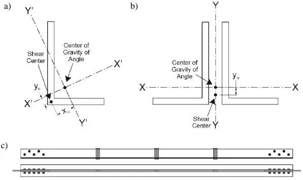
Figure 1.4: Properties of angle cross-sections and build-up brace: a) single angle; b) double angle; c) double angle brace ... 14
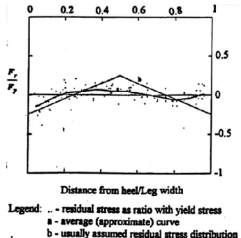
Figure 1.5: Residual stress level along the legs of hot-rolled steel angles (Adluri and Madugula, 1995) ... 15
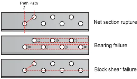
Figure 1.6: Possible failure modes in angles with bolted end connections ... 18
Figure 1.7: Load-displacement curve of each failure mechanism (Castonguay, 2009) ... 19
Figure 1.8: Evaluation of proposed net section strength equation (Wu and Kulak, 1993) ... 22
Figure 1.9: Load vs overall brace elongation (Wu and Kulak, 1993) ... 23
Figure 1.10: Block shear failure (Castonguay, 2009) ... 23
Figure 1.11: Comparison between test and pin-ended model with length KL: a) Hysteretic response with R0= 25, a1= a3= 0.00001, and a2= a4= 0.00002; b) Hysteretic response with R0= 25 and a1to a4= 0.0; c) Out-of-plane response at brace mid-length with R0 = 20 and a1 to a4 = 0.0 (Aguerro et al. 2006) ... 26
Figure 1.12: Pinching4 material used for incremental analyses of brace connections (Castonguay, 2009) ... 27
Figure 1.13: Calibrating of Pinching4 to cyclic results (Castonguay, 2009) ... 28
Figure 1.14: Hybrid model and experimental setup (Schellenberg et al., 2008) ... 29
Figure 1.15: Comparison of storey-drift time-histories and total storey hysteretic-loops (Schellenberg et al., 2008) ... 30
Figure 1.16: Hybrid simulation model (Yang et al., 2009) ... 31
Figure 1.17: Comparison of roof drift (Yang et al., 2009) ... 31
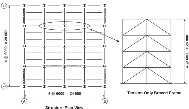
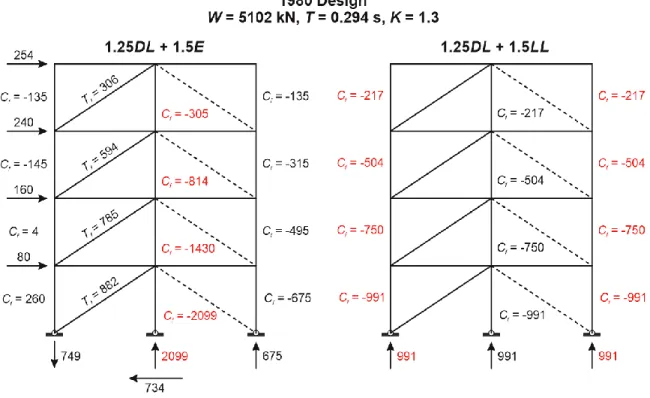
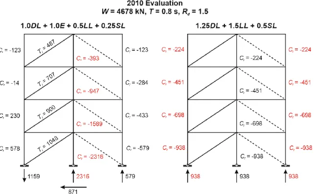
Figure 2.1: Plan view of the structure located at Vancouver ... 34
Figure 2.3: NBCC 1980 design factored member forces in the tension-only braced frame on line
4 ... 37
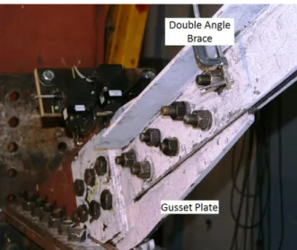
Figure 2.4: Brace connection at level 1 ... 41
Figure 2.5: Connection pattern for double angle brace at level 1 ... 42
Figure 2.6: ETABS model: a) 3D view of the structure model; b) Model of the tension-only braced frame on line 4 ... 45
Figure 2.7: Design factored member forces based on NBCC 2010 ... 48
Figure 2.8: Design force based on brace probable capacity ... 54
Figure 2.9: Existing brace connection at level 1 ... 57
Figure 2.10: Connection strengthen by welding additional plates (Tremblay 2013, personal communication) ... 58
Figure 2.11: Connection strengthen by welding additional plates ... 59
Figure 2.12: Increasing ducility and controlling force of gusset plate net rupture failure mode ... 60
Figure 2.13: Increasing ductiltiy and controlling force by reducing area in shear ... 61
Figure 3.1: Angle coupon fabrication ... 64
Figure 3.2: Stress-strain curve for angle coupon tests: a) Overall strain curve; b) stress-strain curve before stress-strain hardening ... 67
Figure 3.3: Stress-strain curve for gusset plate coupon tests: a) Overall stress-strain curve; b) stress-strain curve up to yielding point ... 69
Figure 3.4: Test platforms: a) Pinned vertical frame; b) 12MN load frame ... 72
Figure 3.5: Brace using in pinned vertical frame test ... 75
Figure 3.6: Strengthened brace ... 75
Figure 3.7: Photo of the test specimen mounted in the pinned vertical frame ... 76
Figure 3.8: Displacement (string pots - SP) transducers for axial deformations: a) location and installation; b) bottom connection; c) top connection ... 77
Figure 3.9: String pots in lateral direction: a) pin clamps; b) string pots ... 78
Figure 3.10: Loading protocol for test in pinned vertical frame ... 79
Figure 3.11: Original gusset plate ... 80
Figure 3.12: Retrofitted gusset plate preparation: a) retrofit strategy II; b) retrofit strategy III .... 81
Figure 3.14: Instrumentation in the 12 MN load frame tests: a) axial direction; b) lateral direction
... 83
Figure 3.15: Braced frame used to develop loading protocol ... 84
Figure 3.16: Loading protocol used in 12 MN load frame tests ... 84
Figure 3.17: Specimen No. 1 - Observed behaviour during the test: a) elastic elongation; b) buckling of brace; c) gap closed in the lower brace segment; d) gap left between the toes of the long legs; e) gap closed in the upper brace segment; f) gap closing between the two vertical legs under brace tension loading; g) contact between the toes of the long legs under compression; h) in-plane bending ... 86
Figure 3.18: Specimen No. 1 - Damage to end connections after the test: a) yielding in the bottom connection; b) yielding in the top connection; c) residual deformed shape of the brace; d) hole elongation in the gusset plate ... 88
Figure 3.19: Specimen No. 1 - Overall brace response: a) axial displacement; b) storey drift... 90
Figure 3.20: Specimen No. 1 - Lateral deformation vs. axial displacement ... 92
Figure 3.21: Specimen No. 1 - Brace connection response in axial direction ... 93
Figure 3.22: Specimen No. 1 - Net brace response under tension ... 94
Figure 3.23: Specimen No. 2 - Observed behaviour during the test: a) Buckling of the brace; b) out-of-plane bending about gusset plate hinge; c) yielding on net section; d) in-plane bending of the brace in the connection region ... 95
Figure 3.24: Specimen No. 2 - Observed damage after the test: a) net section rupture at connection; b) fracture plane; c) necking on short leg; d) cracks near bolt hole; e) necking at net section in the bottom connection; f) yielding of the gusset plate ... 96
Figure 3.25: Specimen No. 2 - Overall brace response ... 98
Figure 3.26: Specimen No. 2 - Connection response in axial direction ... 99
Figure 3.27: Specimen No. 2 - Net brace response under tension load ... 100
Figure 3.28: Specimen No. 2 - Lateral deformation vs. axial displacement ... 100
Figure 3.29: Specimen No. 3 - Observed behaviour of gusset plate in the region with slotted holes during test: a) before test; b) initiation of yielding near the slotted holes; c) yielding of the whole gusset plate; d) necking and initiation of tension rupture of the gusset plate ... 102
Figure 3.30: Specimen No. 3 - Observed behaviour of gusset plate in the region with slotted holes after test: a) gusset plate at bottom; b) gusset plate at top ... 104
Figure 3.31: Specimen No. 3 - Overall brace response ... 106
Figure 3.32: Specimen No. 3 - Brace connection response in axial direction ... 107
Figure 3.33: Specimen No. 3 - Net brace response ... 107
Figure 3.34: Specimen No. 4 - Observed damage after the test: a) relative displacement between the brace and the gusset plate; b) fracture plane; c) & d) local inelastic deformations near the bolt holes in the top (c) and bottom (d) gusset plates ... 109
Figure 3.35: Specimen No. 4 - Overall brace response ... 111
Figure 3.36: Specimen No. 4 - Connection response ... 112
Figure 3.37: Specimen No. 4 - Net brace response ... 112
Figure 3.38: Sketch of existing chevron braced frame ... 115
Figure 3.39: Rusted double angle brace ... 115
Figure 3.40: Separated double angle brace ... 115
Figure 3.41: Original 7/8”A325 bolts ... 116
Figure 3.42: Sketch of the gusset plate fabricated for the test ... 116
Figure 3.43: Test setup for old single angle brace test ... 117
Figure 3.44: Instrumentation at the bottom gusset plate: a) front view; b) side view ... 117
Figure 3.45: Loading protocol for Test LF-OLD-C-1 ... 118
Figure 3.46: Specimen No. 5 - Net section of the old angle brace: a) before test; b) at initiation of yielding; c) upon increasing yielding; d) at necking; e) at initiation of cracking; f) at fracture of the critical region; g) near complete net section rupture ... 120
Figure 3.47: Specimen No. 5 - Observed behaviour during the test: a) in-plane bending; b) buckling of brace; c) opening of the legs (front); d) opening of the legs (back); e) bending at top connection; f) bending at bottom connection ... 122
Figure 3.48: Specimens No. 5 - observed damage after the test: a) residual deformed shape; b) failed cross section ... 123
Figure 3.49: Specimen No. 5 - Overall brace response ... 125
Figure 3.50: Specimen No. 5 - Connection displacement vs. force ... 125
Figure 3.51: Specimen No. 5 - Net brace response ... 126
Figure 3.52: Plan of Retrofit strategy IV for connection ... 127
Figure 3.54: Specimen No. 6 - Observed behaviour: a) top connection after test; b) bottom
connection after test ... 129
Figure 3.55: Specimen No. 6 - Overall brace response ... 131
Figure 3.56: Specimen No. 6 - Connection response ... 131
Figure 3.57: Specimen No. 6 - Net brace response ... 132
Figure 4.1: Single angle model: a) Beam-column elements; b) Brace cross-section with fibers and residual stress patterns; c) Residual stress measurements considered for the L-127x76x9.5 model (from Adluri and Madugula 1995) ... 135
Figure 4.2: Lateral deformation in Y and Z directions at the end of analysis resulting from different initial imperfection conditions ... 137
Figure 4.3: Buckling load comparison between CSA equation and modelling analysis ... 138
Figure 4.4: Built-up double angle brace model: a) Brace configuration and overall model; b) Stitch connection at the brace mid-length; c) Brace cross-section with fibers and residual stress patterns; d) Contact elements and brace end connection modelling ... 139
Figure 4.5: Pinching4 material in OpenSees (Mazzoni et al., 2009) ... 141
Figure 4.6: Connection SAP2000 model: a) original shape; b) bent shape ... 142
Figure 4.7: Model calibration for Test VF-S-C-1: a) brace hysteretic behaviour; b) brace lateral deformation; c) response of bottom connection ... 143
Figure 4.8: Model calibration for test LF-O-C-1: a) brace hysteretic behaviour; b) brace lateral deformation; c) brace connection response ... 145
Figure 4.9: Model calibration for test LF-R1-C-1: a) brace hysteretic behaviour; b) brace lateral deformation; c) brace connection response ... 146
Figure 4.10: Model calibration for Test LF-R1-C-1: a) brace hysteretic behaviour; b) brace lateral deformation; c) brace connection response ... 147
Figure 4.11: Influence of the number of integration points on the: a) Buckling load; b) Energy dissipation; c) Lateral displacement at brace mid-span ... 150
Figure 4.12: Influence of the number of elements and fibre layers across the thickness on the: a) Buckling load; b) Energy dissipation; c) Lateral displacement at brace mid-span ... 151
Figure 4.13:Influence of the number of stitch connectors between the two angles on the: a) Buckling load; b) Energy dissipation; and c) Lateral displacement at brace mid-span ... 152
Figure 5.1: Model of the tension only braced frame with leaning columns at ground floor ... 155
Figure 5.2: Beam-to-column connection behaviour: a) Compression of concrete slab; b) Concrete slab crashed and shear tab is resisting the moment; c) Beam is pressing against the column; d) Moment-rotation hysteretic loops (Liu and Astaneh-Asl, 2004) ... 155
Figure 5.3: Hysteretic loopsofPinching4 material simulating the beam-to-column shear tab connection ... 156
Figure 5.4: Braced frame model for the 4-storey fictitious building ... 156
Figure 5.5: Hybrid simulation model ... 157
Figure 5.6: OpenFresco software architecture for local simulation. (OpenFresco Command Language Manual, 2009) ... 158
Figure 5.7: Configuration of hybrid test setup ... 159
Figure 5.8: Photo of hybrid simulation setup ... 160
Figure 5.9: Ground motion with 0.6 scale factor ... 161
Figure 5.10: Modified ground motion ... 161
Figure 5.11: CPU overloaded problem ... 162
Figure 5.12: Connection timeout problem ... 162
Figure 5.13: Comparison between the original numerical model prediction and hybrid simulation: a) Lateral displacement time history at the first-storey; b) Brace hysteretic response ... 163
Figure 5.14: Comparison between modified numerical model analysis and hybrid simulation: a) Lateral displacement time history at the first-storey; b) Brace hysteretic response ... 164
Figure 5.15: Comparison between original numerical model prediction and hybrid simulation: a) Lateral displacement time history at the first-storey; b) Brace hysteretic response ... 167
Figure 5.16: Comparison between modified numerical model analysis and hybrid simulation: a) Lateral displacement time history at the first-storey; b) Brace hysteretic response ... 167
Figure 6.1: Design forces in the retrofitted braced frame ... 174
Figure 6.2: 4-storey braced frame model ... 176
Figure 6.3: Beam with hinge element ... 178
Figure 6.4: Design uniform hazard spectrum and scaled acceleration spectra of selected ground motions ... 180
Figure 6.5: Collapsed structure corresponding to different storey failure ... 181
Figure 6.7: Time-history response: a) Ground motion accelerogram; b) Storey lateral
displacements; c) Inter-storey drifts; d) Axial force in the braces at ground floor level; e) Axial force in the frame columns at the ground floor level; f) Bending moment at the top of the frame columns at the ground level ... 183 Figure 6.8: Brace hysteretic behaviour at GF level: a) sum of two connections; b) angle brace with connections ... 185 Figure 6.9: Brace hysteretic behaviour at the 2nd floor level: a) sum of two connections; b) angle brace with connections ... 185 Figure 6.10: Axial force-bending moment interaction diagrams: a) to m) Columns 1 to 13 ... 186 Figure 6.11: Shear force in columns ... 188 Figure 6.12: MCE response spectra for the corresponding ground motion intensities (FEMA P695) ... 192 Figure 6.13: The collapse interception and collapse fragility curves of structure models: a) fitted fragility curve by considering RTR; b) modified fragility curve by considering TOT ... 193
Figure 6.14: Observed collapse and collapse fragility curve for structures under 60%Vdesign,
criteria: a) fitted fragility curve only considering RTR; b) modified fragility curve considering
TOT ... 199
Figure I. 1: Inter-storey drift for CBFdesign+exp. model under earthquake NGA-15 with Fsm 1.2 .. 211
Figure I. 2: Inter-storey drift for CBFdesign+exp. model under earthquake NGA-57 with Fsm 1.2 .. 211
Figure I. 3:Inter-storey drift for CBFdesign+exp. model under earthquake NGA-762 with Fsm 1.25 211
Figure I. 4:Inter-storey drift for CBFdesign+exp. model under earthquake NGA-776 with Fsm 1.1 . 212
Figure I. 5:Inter-storey drift for CBFdesign+exp. model under earthquake NGA-796 with Fsm 1.0 . 212
Figure I. 6:Inter-storey drift for CBFdesign+exp. model under earthquake NGA-807 with Fsm 1.2 . 212
Figure I. 7:Inter-storey drift for CBFdesign+exp. model under earthquake NGA-838 with Fsm 1.0 . 213
Figure I. 8:Inter-storey drift for CBFdesign+exp. model under earthquake NGA-900 with Fsm 1.0 . 213
Figure I. 9:Inter-storey drift for CBFdesign+exp. model under earthquake NGA-935 with Fsm 1.25
... 213 Figure I. 10:Inter-storey drift for CBFdesign+exp. model under earthquake NGA-975 with Fsm 1.1
Figure I. 11:Inter-storey drift for CBFdesign+exp. model under earthquake NGA-1005 with Fsm 1.25
... 214 Figure I. 12:Inter-storey drift for CBFdesign+exp. model under earthquake NGA-1006 with Fsm 1.0
... 214 Figure I. 13:Inter-storey drift for CBFdesign model under earthquake NGA-15 with Fsm 1.1 ... 215
Figure I. 14:Inter-storey drift for CBFdesign model under earthquake NGA-776 with Fsm 1.0 ... 215
Figure I. 15:Inter-storey drift for CBFdesign model under earthquake NGA-787 with Fsm 1.0 ... 215
Figure I. 16:Inter-storey drift for CBFdesign model under earthquake NGA-796 with Fsm 0.8 ... 216
Figure I. 17:Inter-storey drift for CBFdesign model under earthquake NGA-838 with Fsm 1.1 ... 216
Figure I. 18:Inter-storey drift for CBFdesign model under earthquake NGA-900 with Fsm 1.0 ... 216
Figure I. 19:Inter-storey drift for CBFdesign model under earthquake NGA-953 with Fsm 0.9 ... 217
Figure I. 20:Inter-storey drift for CBFdesign model under earthquake NGA-1787 with Fsm 0.9 ... 217
Figure I. 21:Inter-storey drift for CBFretrofit+exp. model under earthquake NGA-735 with Fsm 1.1
... 218 Figure I. 22:Inter-storey drift for CBFretrofit+exp. model under earthquake NGA-762 with Fsm 1.2
... 218 Figure I. 23:Inter-storey drift for CBFretrofit+exp. model under earthquake NGA-776 with Fsm 0.8
... 218 Figure I. 24:Inter-storey drift for CBFretrofit+exp. model under earthquake NGA-787 with Fsm 1.1
... 219 Figure I. 25:Inter-storey drift for CBFretrofit+exp. model under earthquake NGA-796 with Fsm 0.9
... 219 Figure I. 26:Inter-storey drift for CBFretrofit+exp. model under earthquake NGA-807 with Fsm 1.2
... 219 Figure I. 27:Inter-storey drift for CBFretrofit+exp. model under earthquake NGA-838 with Fsm 1.2
... 220 Figure I. 28:Inter-storey drift for CBFretrofit+exp. model under earthquake NGA-900 with Fsm 0.8
... 220 Figure I. 29:Inter-storey drift for CBFretrofit+exp. model under earthquake NGA-935 with Fsm 1.0
Figure I. 30:Inter-storey drift for CBFretrofit+exp. model under earthquake NGA-1787 with Fsm 1.0
LIST OF TABLES
Table 2.1: Minimum specified gravity loads ... 35 Table 2.2: Brace section and demand-to-capacity (stress) ratios ... 39 Table 2.3: Column sections and demand-to-capacity ratios ... 39 Table 2.4: Beam section and demand-to-capacity ratios ... 40 Table 2.5: Brace connection design ... 42 Table 2.6: Connections' demand-to-capacity ratios ... 43 Table 2.7: Brace design force comparison ... 44 Table 2.8: Brace demand-to-capacity ratios ... 49 Table 2.9: Column demand-to-capacity ratios ... 49 Table 2.10: Beam demand-to-capacity ratios ... 50 Table 2.11: Connection failure modes and demand-to-capacity ratios ... 52 Table 2.12: Column resistance demand-to-capacity ratios ... 55 Table 2.13: Beam resistance demand-to-capacity ratios ... 55 Table 2.14: Connection failure modes and demand-to-capacity ratios ... 56 Table 2.15: Factored and probable resistance capacities of connections ... 62 Table 3.1: Geometrical properties of the coupons ... 65 Table 3.2: Measured mechanical properties of the angles from coupon tests ... 68 Table 3.3: Measured mechanical properties from coupon tests ... 69 Table 3.4: Test program ... 71 Table 3.5: Key response parameters for specimen No.1 ... 90 Table 3.6: Key response parameters for specimen No.2 ... 98 Table 3.7: Important response parameters for specimen No.3 ... 106 Table 3.8: Key response parameters for specimen No.4 ... 111 Table 3.9: Factored, probable and measured connection resistances ... 113 Table 3.10: Key response parameters for specimen No.5 ... 124 Table 3.11: Key response parameters for specimen No.6 ... 130 Table 4.1: Parameters used to define the Steel02 material ... 136 Table 5.1: Hybrid simulation test program ... 161 Table 6.1: Selected ground motion records ... 179 Table 6.2: Summary for collapsed structure in analysis ... 190
Table 6.3: Spectral shape factor (FEMA P695) ... 192 Table 6.4: CMR and ACMR parameters ... 193 Table 6.5: Parameters for the fragility function and uncertainty factors ... 194 Table 6.6: Quality rating of design requirements (FEMA P695) ... 195 Table 6.7: Quality rating of test data from an experimental investigation program (FEMA P695) ... 196 Table 6.8: Quality rating of index archetype model (FEMA P695) ... 197 Table 6.9: Acceptable values of ACMR (FEMA P695) ... 198 Table 6.10: CMR and ACMR under 60%, Vdesign, criteria ... 199
LIST OF SYMBOLS
A Ground acceleration ratio in NBCC 1980.
Acn Net cross-section area of the connected leg at the critical cross-section (mm2). Ag Gross area (mm2).
Agv Gross area in shear for block failure (mm2). An Net area (mm2).
Ane Effective net area (mm2).
Ao Gross cross-section area of the outstanding leg (mm2). Br Factored bearing resistance of a member or component (kN). Cf-10 Factored compressive design force in columns in 2010 design (kN). Cf-10p Probable compressive design force in columns (kN).
Cf-80 Factored compressive design force in columns in 1980 design (kN).
Cr-10 Factored buckling strength of columns using equation provided in CSA S16-09 (kN).
Cr-80 Factored buckling strength of columns using equation provided in CSA S16-M78 (kN).
Cu-10 Expected buckling load of columns (kN). C’u Post-buckling compressive resistance (kN). d Nominal bolt diameter (mm).
e Distance from center of hole to an edge in bolted connections (mm). F Foundation factor or soil condition factor.
Fx Seismic force at every level (kN).
Fu Specified minimum tensile strength (MPa).
Fsm Modification factor used to adjust scaling factor (Sf) in incremental analysis. Fy Specified minimum yield stress or yield strength (MPa).
g Transverse spacing between fastener gauge lines (mm). hn Total building height (m).
hs Storey height (m).
hsm Inter-storey drift in percentage. I Importance factor of the structure.
K Numerical coefficient that reflects the material and type of construction, damping, ductility and/or energy-absorptive capacity of the structure in NBCC 1970, 1975, 1980 and 1985.
KL Effective length (mm). L Brace length (mm).
Mw Seismic moment magnitude n Number of bolts.
R Force modification factor that reflects the capability of a structure to dissipate energy through inelastic behaviour in NBCC 1990 and 1995.
Rd Seismic force reduction factor accounting for system ductility. Ro Seismic force reduction factor accounting for system overstrength.
Rt Ratio of expected tensile strength to the specified minimum tensile strength, Fu.
Ry Ratio of expected yield strength to the specified minimum yield strength, Fy rx Radius of gyration of a single-angle member about its geometric axis parallel
to the connected leg (mm).
ry Radius of gyration of a member about its weak axis (mm).
S Seismic response factor in NBCC 1980.
Sf Scaling factor used to scale historical earthquakes to respective NBCC uniform hazard spectrum.
s Centre-to-centre longitudinal spacing (pitch) of any two successive fastener holes (mm).
Temp Structural fundamental period based on NBCC formula (s). Tf-10 Factored tensile force in braces in 2010 design (kN). Tf-10p Probable tensile force in braces (kN).
Tf-80 Factored tensile force in braces in 1980 design (kN).
Tr-10 Factored tensile resistance of braces using equation provided in CSA S16-09 (kN).
Tr-80 Factored tensile resistance of braces using equation provided in CSA S16-M78 (kN).
Tr-c-10 Factored tensile resistance of brace connections using equation provided in CSA S16-09 (kN).
Tr-c-80 Factored tensile resistance of brace connections using equation provided in CSA S16-M78 (kN).
Tu Probable tensile resistance of braces (kN).
Tu-c-10 Probable tensile resistance of brace connections (kN). tg Thickness of gusset plate (mm).
V Seismic base shear based on the NBCC 2010 equivalent static force procedure (kN)
Vc Column shear limitation (kN).
Vd Elastic seismic base shear coming from the response spectrum analyses, Ve, multiplied by Ie/RdRo (kN).
Vdesign The seismic base shear was used to design existing structure in 1980(kN). Ve Elastic seismic base shear coming from the response spectrum analysis (kN).
VP-∆ Storey shear produced by the overturning moment of the gravity load (kN). Vr Factored shear resistance of a member or component (kN).
W Structure seismic weight (kN).
We Whitmore’s effective gusset plate width (mm).
Brace and brace connections axial deformation or controlling axial displacement (mm).
b Net brace axial deformation (mm).
c Brace connections axial deformation (mm). lat. Brace lateral deformation (mm).
o Brace initial out-of-straightness (mm). T Period-based ductility.
LIST OF APPENDICES
INTRODUCTION
BackgroundIn Canada, the National Building Code of Canada (NBCC) provides seismic loading and analysis requirements for building structures, whereas special seismic design and detailing provisions for steel structures are prescribed in the CSA S16 steel structure design standard. Since the introduction of the first seismic design provisions in NBCC 1941, 13 different versions of NBCC were published (Mitchell et al., 2010). The current edition of NBCC was released in 2010 (NRCC, 2010). The concepts and methods that are given in the NBCC for the seismic analysis and design of seismic force resisting systems, employed in building structures, have consistently improved during the last 70 years. The knowledge gained on seismic hazard and structural seismic response evolved markedly. In particular, the methods for the calculation of the minimum seismic design loading have been improved significantly. Although 13 different versions of CSA S16 steel structure design standard corresponding to each version of the NBCC were available to designers during the same period of time, the first ductile seismic design and detailing provisions given in CSA S16 were only implemented in 1989, which means that CSA S16 did not contain any rule to ensure ductility levels consistent with the NBCC loading prior to 1989. Since then, new research findings and lessons learned from the recent past earthquakes have been continually updated in the CSA S16 provisions (Tremblay, 2011).
Seismic deficiencies and lack of lateral resistance and/or ductility are expected for steel structures designed and built before the 1990s and their performance is uncertain in case of a severe earthquake. Accurate seismic assessment of steel structures built before 1989 needs to be carried out to identify potential seismic deficiencies and their possible consequences. In order to prevent severe damage that can lead to structural failure or collapse, the results of such an assessment can then be used to decide on the necessity of seismic retrofitting.
Limited information is available for the seismic evaluation and retrofit of steel structures. In addition, different assessment results can be obtained when different assessment methods are used. Moreover, there is no standard to evaluate these results. The first time when requirements for seismic retrofit of existing structures were addressed in the NBCC was given in Commentary “L” of NBCC 2010. In that commentary, it is recommended that buildings that have been designed for
an earthquake load, Vdesign, less than 0.6 times the minimum earthquake load specified in NBCC
2010 must be seismically upgraded.
Nowadays, seismic analysis and strength verification is typically performed automatically using computer programs such as ETABS (CSI 2009). Response spectrum analysis performed in the elastic range is now preferred to the equivalent static force procedure to evaluate earthquake effects on structures. By employing automatic computations, an engineer can rapidly determine the seismic design forces in the structure. The OpenSees finite element program (Mazzoni, 2006) has been developed to predict the inelastic seismic structure response through nonlinear time history analysis. The program can also be used to examine the consequences of identified deficiencies. The accuracy of OpenSees structural models can be validated and verified using the hybrid simulation technology where the OpenSees finite element analysis model and the OpenFresco middleware (Schellenberg et al., 2006) are combined. In this technology, critical structural components are physically tested in the laboratory while performing the seismic analysis of the whole structure.
Once it is determined that an existing structure needs to be retrofitted, different retrofit strategies must be established and compared to evaluate costs, retrofitting time, and the seismic performance after the retrofit has been implemented. Generally, retrofit strategies can be divided into two major categories: conventional retrofit technologies and innovative retrofit technologies. While the conventional retrofit technologies typically involves strengthening of structure, the second group often calls for the addition of energy dissipating devices. Normally, the cost of a conventional retrofit method is lower than that of adding energy dissipation devices; however, the ductility performance is better enhanced when energy dissipating devices are considered in design. Extensive seismic upgrade projects have been performed by using innovative retrofit technologies. However, due to its appealing lower costs, there is a need to develop more conventional retrofit technologies that can help achieving an improved seismic response. The performance of such retrofitted structures can be evaluated using OpenSees models or hybrid testing.
A large number of existing structures were built before the 1990s. Among these structures, many are low-rise steel structures such as commercial buildings, factories, hospitals and schools. These structures are typically less than five storeys in height. Steel braced frames are very popular SFRSs for these structures. In these braced frames, built-up double angle braces were commonly used as
brace sections. One reason for this preference is the ease of connections of angle braces to either single vertical gusset plates or connecting plates. Due to the shape of the cross-section of double angles, their tensile strength is higher than their compression resistance. Thus, theses braces have been very commonly used in tension-only braced frames. In existing steel braced frames, failure of brace connections that were designed without details to ensure a ductile performance is considered as one of the most critical deficiencies.
Finite element models of built-up double angle sections and their connections have not been created yet in the OpenSees framework. Hence, the development and calibration of an accurate model is necessary to predict the inelastic seismic response of double angle braces and their connections in OpenSees. OpenSees models have already been used extensively in recent years by researchers (Aguero et al., 2006; Uriz et al. 2008; Tremblay et al., 2009; Castonguay, 2009; Chen 2011), but the capability of accurately predicting structural collapse due to failure of brace connections has not been validated yet. Hybrid simulation using OpenSees and OpenFresco has already been used for braced frame analysis (Yang et al., 2006; Schellenberg et al, 2008). However, no test program has been devoted to the evaluation of deficient existing structures or the validation of retrofit strategies.
Objectives
The principal objective of this project is to perform the seismic assessment and retrofit of a steel concentrically braced frame (CBF) for a low-rise existing structure that was built prior to 1989. The study should examine seismic deficiencies related to the braces and their connections. Conventional retrofit technologies should be proposed and their feasibility verified. The project should also serve to the development of knowledge on the assessment of seismic deficiencies for existing steel building and the evaluation of the seismic performance of retrofitted buildings. More specifically, this project will focus on the following objectives:
Identify potential seismic deficiencies for braced frames built with double angle braces. Propose possible seismic retrofit strategies.
Develop an OpenSees model to predict the seismic response of built-up double angle brace members and their connections.
Calibrate the built-up double angle braces and brace connections model using cyclic quasi-static tests.
Use the hybrid simulation technique with the OpenFresco platform to verify the OpenSees model.
Use the calibrated OpenSees model to carry nonlinear time history analysis of an existing deficient structure to examine its capacity against collapse in the as-built and retrofitted conditions.
Methodology
To attain these objectives, this project can be divided into four main parts: an assessment part, an OpenSees model development and calibration part, a hybrid simulation part, and a final detailed seismic performance assessment part.
In the design standard assessment part, a braced frame using built-up double angle braces for a prototype low-rise steel building is designed using a version of the NBCC and CSA S16 standard in force prior to 1990. This existing structure is evaluated by using the latest code design provisions. For this purpose, an ETABS model is created to perform response spectrum analysis to determine the seismic demand and find out potential seismic deficiencies. Possible conventional retrofit strategies are proposed to address the identified deficiencies.
In the OpenSees model development and calibration part, a model is developed for the built-up double angle braces. A quasi-static test program is performed on double angle braces with their connections to generate sufficient data for the calibration of the brace model. All tests are carried out on the bracing member of the first-storey of the prototype building. In the quasi-static cyclic tests, double angle braces with the original connections and retrofitted connections are tested. In the hybrid simulation part of this project, the double angle braces model is used to develop a simplified model of the entire braced frame that will be used to predict the behaviour of existing structure under seismic events. Two models are developed: one with the original braced frame and one with the retrofitted structure. For the hybrid simulation, a full-scale brace specimen with its connections is tested in the laboratory. The rest of the braced frame is reproduced with the numerical model. OpenFresco commands are introduced in the numerical model to ensure communication with the laboratory loading equipment. A total of four hybrid tests were carried out to verify the OpenSees model predictions.
In the last part of the project, extensive nonlinear dynamic analysis of the prototype structure are performed to evaluate the consequences of the existing structure deficiencies and assess the benefits resulting from the implementation of the proposed retrofit strategy. The structure models were expanded to also include the gravity frame. Nonlinear beam-column connections were considered in the models. Two series of analysis are performed for the existing structure: one assuming the calculated resistances of the brace connections and one assuming the measured resistances of the brace connections. A third model is also developed that includes two of the retrofit strategies that have been proposed and studied experimentally. Incremental dynamic analysis was carried out in all cases to develop fragility curves. The adequacy of the structure performance was determined using the FEMA P695 approach (FEMA 2009).
Organization of thesis
The thesis includes seven chapters:
Chapter 1 consists of literature review, including a comparison of the NBCC versions from 1970 to 2010.
Chapter 2 presents the design and assessment of the prototype building, together with the proposed retrofit methods.
Chapter 3 describes the coupon tests and the quasi-static tests performed on the double angle braces and their connections. Testing of the proposed retrofit strategies is also described in this chapter.
Chapter 4 presents the development of the OpenSees model of the built-up double angle braces and their connections. The model calibration is also presented in this chapter. Chapter 5 describes the tension-only braced frame modelling in OpenSees. The hybrid test
program is presented in this chapter. The test results are also presented and discussed. Difficulties faced in braced frame numerical model analysis and the hybrid simulations are also introduced.
Chapter 6 presents the detailed seismic assessment of the building structure using nonlinear dynamic analysis. An expanded braced frame model is introduced. This model is used to carry out incremental time history analysis under twenty selected ground motions to evaluate the collapse capacity of the structure for three different conditions. The results of this assessment work are presented and discussed.
Chapter 7 concludes the research project. Recommendations for existing building assessment, retrofitting strategies, and model analysis are given. Possible future work is also discussed.
CHAPTER 1: LITERATURE REVIEW
The literature review of this research project includes four parts. The first part referrers to literature review for seismic assessment of existing building assessment according to the National Building Code of Canada and the CSA S16 standard for steel structures. The second part addresses previous research work performed on the behaviour of double angle braces and their connections under earthquake loads. The third part is assigned to previous modelling studies conducted on double angle braces, braces connections, and braced frames. The last part reports on hybrid simulation technique used in seismic structural engineering.
1.1 NBCC Seismic Loads
A study providing a summary of the evolution of seismic design in Canada was presented by Mitchell el al. (2010). In particular, the seismic base shear values have evolved significantly over the last 70 years due to changes in the approach taken for determining seismic hazards and seismic hazard maps. The design philosophy had also changed from working stress design to ultimate strength design, with the introduction of load factors and capacity reduction factors, and then to limit states design, with load factors resistance factors. This paper discussed important parameters that affect the seismic base shear such as the building period, structure type factor, soil factor, and ductility factor.
To illustrate the code changes, the seismic design base shears determined from different versions of the National Building Code of Canada for the 2- and 10-storey reinforced concrete frame structures located in Montreal and Vancouver are compared in Figure 1.1. The ductile design concept was first introduced in NBCC 1970, and structures designed prior to 1970 were considered as conventional structures. Seismic resistant systems designed with ductility factor R = 2 and 3 in seismic design provisions after 1990 were referred to nominally ductile systems. In the figure, it is clear that design shear forces were too small compared with current design force levels for conventional structures built before 2005, especially for low-rise buildings in Montreal.
Figure 1.1: Comparisons of ‘‘factored’’ design base shears for concrete moment resisting frame structures in Montreal and Vancouver. Note that values of V/W before 1965 were based on working stress design and hence were multiplied by 2 for comparison (a) two-storey frame (Montreal), (b) ten-storey frame (Montreal), (c) two-storey frame (Vancouver), and (d) ten-storey
frame (Vancouver) (Mitchell et al., 2010)
Additional base shear comparisons were performed as part of this project for the selection of a prototype building for the study. The comparison focuses on the seismic design provisions of NBCC 1970 to NBCC 2010. Although the first seismic design provisions were introduced in NBCC 1941, the first truly probabilistic seismic map developed by Milne and Davenport in 1969 was only adopted in NBCC 1970.
The spectra were calculated for two cities in the eastern part of Canada (Montreal and Ottawa), and for two cities (Vancouver and Victoria) near the western coast. The calculations were performed for a prototype structure assumed to be a commercial building built on very dense soil or soft rock. The lateral loads were assumed to be resisted by tension-only steel braced frames, which is considered as a conventional construction category (CC type) structure in NBCC 2005 and 2010. The importance factor and the foundation factor for this structure were considered as 1.0. Ductility factor K in NBCC 1970 to 1985 was set equal to 1.3. The ductility factor R used was 1.5 in NBCC 1990 to 2010 for Type CC structures. Figure 1.2 shows the comparison between the spectra for the four aforementioned cities. Generally, all seismic design provisions give similar design base shears for medium- to high-rise buildings that have the fundamental period longer than 1.0s. The
differences in design base shears for these structures are smaller for cities in eastern Canada than for the cities in the west. For low-rise structures that have periods less than 1.0 s, the design base shears exhibit large differences among the different seismic design provisions. Similar design base shears were obtained for NBCC 1970 to NBCC 1980, but those values are the lowest. Starting with NBCC 1985 when an updated seismic map was included, the design base shear began to increase. For example, design base shear from NBCC 1990 and NBCC 1995 increased about twice when compared to the lowest illustrated values. Then, it increased about 4 to 5 times when comparing to NBCC 2005 and 2010. Although the exact changes for certain buildings may not be as high because other modifications were also implemented in NBCC, such as the equations for the building periods. This comparison of different design spectra provides a general idea about the variations in design base shears over the last 5 decades. The results clearly show that low- and medium-rise building structures will very likely require major retrofit action, while the situation is more critical for structures designed and built prior to 1989.
a)
b)
c)
d)
Figure 1.2: Spectrum analysis results: a) Montreal; b) Ottawa; c) Vancouver; d) Victoria (Continued)
Based on this survey, it appears that the assessment of the seismic performance of a low-rise building that was built in 1980 would be most interesting because NBCC 1980 required nearly the smallest design base shear among the editions released between 1970 and 1985.
It is important to mention that dynamic analysis was permitted to be used as an alternative procedure to determine the seismic design forces in the 1975 NBCC. Since then, because computers became used in structural analysis, dynamic analysis was gradually adopted by structural engineers.
1.2 Seismic design and detailing provisions in CSA S16
In Canada, the design of steel structures is performed in accordance with the CSA S16 design standards. Seismic design and detailing provisions in CSA S16 were only implemented in 1989. Since then, they have been continually updated to reflect new research findings and lessons learned in recent past earthquakes (Tremblay, 2011).
Prior to 1989, there were no special design and detailing provisions in S16 to ensure ductile seismic response. For instance, all members and connections were designed for the same load combinations and a brittle failure mode (e.g., tension rupture on net section) could be the governing failure mode along the seismic load path of the structure. In 1989, capacity design provisions were introduced in CSA S16 to establish a strength hierarchy along the seismic load paths such that inelastic demand will develop in ductile elements capable of accommodating the anticipated inelastic deformations and sufficient resistance are provided to non-ductile elements in order to assure their elastic response.
For a given seismic force resisting system, the ductile (yielding) elements are identified in CSA S16 and special detailing requirements are prescribed so that they can withstand the inelastic deformations without premature fracture. For the remaining, non-ductile (capacity protected) elements, the seismic induced forces are increased to the level corresponding to the probable resistance of the ductile elements. For instance, in steel braced frames, the bracing members are selected to be the ductile elements. Brace connections, columns, beams and other connections along the seismic load path must be designed to resist seismic loads required to develop the probable resistance of the braces. Thus, the seismic force resisting systems should have a ductility consistent with the seismic loads that are specified in the NBCC such that a ductile and stable inelastic response can be safely achieved under the design level earthquake. This project focuses on braced frames with double angle steel bracing members and bolted connections. The inelastic seismic responses of this type of bracing members is reviewed in the following sections, together with the design equations that are used for brace bolted connections. These aspects are of particular importance when performing the seismic design or seismic assessment of these braced frames.
1.3 Built-up double angle braces
Angle braces, either single angle brace or built-up double angle braces, have been and still are very popular for steel concentrically braced frames. For instance, in the AISC design guideline on connections published in the early 1980's (AISC, 1984), almost all illustrated bracing members are made of angle sections. One reason may be the facility of connections fabrication and installation for angle braces. This characteristic of the angle braces led to an extensive usage of angle braces in the construction field.
1.3.1 Cyclic-inelastic behaviour of double angle bracing members
The behaviour of double angle braces with bolted or welded connections was investigated by Astaneh-Asl and Goel (1984, 1985). In their cyclic tests, in-plane and out-of-plane brace buckling was observed. In both cases, it was found that the buckling load decreases significantly after the angle brace has buckled. After buckling, the compressive resistance continues to decrease gradually in the following loading cycles. In tension, braces can develop their full probable yield tensile resistances based on the gross-section yielding, provided that their connections have sufficient resistance.
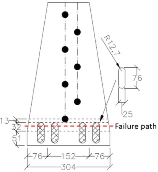
From the observations made in the out-of-plane buckling tests, the authors proposed that the gusset plates be designed with a smaller flexural strength and stiffness compared to the double angle brace members such that ductile rotation takes place in the gusset plates upon brace buckling. With this design, three plastic hinges formed in the braces: one at the brace mid-span and both in the gusset plates. In the tests conducted by Astaneh-Asl and Goel (1984), the gusset plates generally showed poor ductility and early fractures, due to undesirable constraint which prevented plastic hinge free rotation at the ends during post buckling stage. As shown in Figure 1.3, they recommended to leave a minimum free distance of twice the thickness of the gusset plate between the end of the double angle brace and the corner of gusset plate to ensure the free formation of plastic hinges.
Figure 1.3: Free length of gusset plate
The deformed shape of double angle braces with long legs back-to-back is nearly a half-sine curve resulting in effective length factor of approximately 1.0. It was indicated that flexural yielding in the gusset plates occurred before that in the angles brace because the combined effect of bending and axial load in the post-buckling region. Local buckling was observed at the outstanding legs of