UNIVERSITÉ DE MONTRÉAL
SOLID PARTICLE EROSION MECHANISMS OF PROTECTIVE COATINGS
FOR AEROSPACE APPLICATIONS
ETIENNE BOUSSER
DÉPARTEMENT DE GÉNIE PHYSIQUE ÉCOLE POLYTECHNIQUE DE MONTRÉAL
THÈSE PRÉSENTÉE EN VUE DE L’OBTENTION DU DIPLÔME DE PHILOSOPHIÆ DOCTOR
(GÉNIE PHYSIQUE) AVRIL 2013
UNIVERSITÉ DE MONTRÉAL
ÉCOLE POLYTECHNIQUE DE MONTRÉAL
Cette thèse intitulée:
SOLID PARTICLE EROSION MECHANISMS OF PROTECTIVE COATINGS FOR AEROSPACE APPLICATIONS
présentée par : BOUSSER Etienne
en vue de l’obtention du diplôme de : Philosophiæ Doctor a été dûment acceptéH par le jury d’examen constitué de :
M. DESJARDINS Patrick, Ph. D., président
Mme SAPIEHA Jolanta Ewa, Ph. D., membre et directrice de recherche M. MARTINU Ludvik, Ph. D., membre et codirecteur de recherche M. LÉVESQUE Martin, Ph. D., membre
ACKNOWLEDGMENTS
First of all, I wish to thank my thesis directors, Professors Jolanta Sapieha and Ludvik Martinu for taking a chance on a mechanical engineer who had much to learn on physical science. I thank you both for your guidance and support, but most of all for the trust you place in me.
Furthermore, I would like to thank Professor Patrick Desjardins, Professor Allan Matthews, and Professor Martin Lévesque for accepting to evaluate my PhD thesis and be members of the jury. I would like to thank all the partners I’ve had the pleasure of working with on this project: Pratt and Whitney Canada, MDS Coatings Technologies, Bell Helicopter Textron Ltd, McGill University, Université de Sherbrooke and the Nation Research Council’s Aerospace Research Institute. I would also like to acknowledge the financial support from the Natural Sciences and Engineering Research Council (NSERC) of Canada, the Consortium for Research and Innovation in Aerospace in Québec (CRIAQ) and the Fonds de recherche du Québec - Nature et Technologies (FQRNT).
During the more than nine years I’ve spent at the Functional Coatings and Surface Engineering Laboratory (FCSEL), I’ve had the pleasure of working with many gifted and kind people. Most are colleagues and some have become friends, but all have contributed in their way to the person and researcher I am today. Thanks to: Aram Amassian, Marwan Azzi, Bill Baloukas, Moushab Benkahoul, Samih Beskri, Jiri Capek, Marie-Maude de Denus Baillargeon, Mariusz Dudek, Jean-Philippe Fortier, Simon Gaudet, Srinivasan Guruvenket, Soroush Hafezian, Matej Hala, Salim Hassani, Christophe Hecquet, Pawel Jedrzejowski, Ganesh Kamath, Jean-Michel Lamarre, Stéphane Larouche, Duanji Li, Simon Loquai, Viktor Marushka, Jean-Philippe Masse, Matjaz Panjan , Thomas Poirié, Fabrice Pougoum, Édouard Proust, Alexis Ragusich, Philippe Robin, Thomas Schmitt, Luc Vernhes, Richard Vernhes, Nicolas Viau and Oleg Zabeida. I apologize in advance if I have forgotten anyone; nothing is meant by it except that I am forgetful.
I would like to thank all the co-authors of my papers and all who’ve helped one way or another in the advancement of my project. In particular, I could not have done any of the work without the technical assistance of Sébastien Chenard, Yves Drolet and particularly Francis Turcot with whom I’ve spent many hours making things work.
I would like to specifically thank Professor Rony Snyders from the Université de Mons for his friendship and the many collaborative projects we’ve worked on together. I also owe him a large debt of gratitude for making me rediscover my love for the beautiful game.
Finally, I can’t express enough my gratitude to my parents who have been my greatest role models and given so much that has made me the person I am today. Last but not least, is the love and thanks I have for my wife Caroline. Without her, no part of this project would have been possible. Thank you for our wonderful life together.
RÉSUMÉ
Le progrès économique et technologique ainsi que les considérations environnementales nécessitent la conception d’équipements de plus en plus performants, sollicitant les composantes aux limites de leur capacité. Une conséquence importante de cette demande accrue au niveau de la performance est que les lacunes de type tribologique, telles que la dégradation du lubrifiant, l’usure excessive et la tribocorrosion, peuvent être amplifiées de façon significative, menant à des coûts d’exploitation additionnels, une efficacité moindre et une défaillance prématurée. Puisque les processus tribologiques découlent de l’interaction entre au moins deux corps en mouvement relatif dans un environnement donné, l’ingénierie de surface peut permettre de conférer aux surfaces la performance de pointe requise lorsque les conditions de fonctionnement sont très exigeantes. Dans ce contexte, la conception de systèmes de matériaux appropriés doit être guidée par une connaissance poussée des mécanismes de dégradation et de la réponse de la surface au chargement et à la déformation, qui agissent souvent de façon synergique.
L’érosion par impact de particules solides (EIPS) survient lorsque des particules solides dures, présentes dans l’environnement, sont entraînées par un fluide et impactent les surfaces de composantes. Ce type de dommage est spécifiquement marqué dans la première section d’un moteur d’avion, où les pales du compresseur peuvent s’éroder à un point tel que la performance aérodynamique et même l’intégrité structurale sont compromises. Ainsi, de nombreux travaux de recherche ont été réalisés dans les secteurs académique et industriel afin de comprendre les mécanismes de perte de matière impliqués dans l’EIPS et afin de développer des technologies protectrices dans le but d’améliorer la durée de vie utile des composantes. Un exemple est l’utilisation de revêtements protecteurs durs afin de limiter l’érosion des composantes de moteur d’avion, qui sont pour la plupart métalliques.
Dans cette optique, l’objectif principal de ce projet de doctorat est d’étudier les mécanismes de perte de matière pendant l’EIPS de couches dures protectrices, incluant les systèmes nanocomposites et nanostructurés. De plus, étant donné la nature complexe des mécanismes d’EIPS, des méthodologies expérimentales rigoureuses doivent être mises en œuvre, et les effets de tous les paramètres de test impliqués doivent être entièrement compris. Dans cette thèse de doctorat, l’importance de la méthodologie expérimentale est mise de l’avant tout au long du
projet, afin d’étudier de façon éclairée les mécanismes d’EIPS des matériaux fragiles et des revêtements dures.
Dans l’étape initiale de cette thèse, nous avons étudié l’effet de l’ajout de silicium (Si) sur la microstructure, les propriétés mécaniques et, plus spécifiquement, sur la résistance à l’EIPS de couches épaisses de type CrN. Nous avons observé que l’ajout de Si améliorait de façon significative la résistance à l’érosion et que l’EIPS était corrélée avec les valeurs de microdureté, i.e. les couches ayant la microdureté la plus élevée présentaient aussi les taux d’érosion (TE) les plus bas. En fait, les TE se sont révélés être beaucoup plus dépendants de la dureté de surface que ce qui avait été proposé auparavant pour les mécanismes d’érosion fragiles.
À partir de ces résultats initiaux, quatre objectifs spécifiques ont été formulés pour ce projet de doctorat: a) développer une méthodologie solide pour la caractérisation de l’EIPS des systèmes de revêtements, b) étudier les effets des propriétés des particules sur les mécanismes d’EIPS des matériaux fragiles, c) déterminer la relation entre les propriétés mécaniques de revêtements et leur comportement sous EIPS, et d) développer une méthodologie expérimentale in situ résolue dans le temps afin d’étudier les mécanismes d’EIPS des systèmes de revêtements protecteurs. Les résultats principaux sont présentés sous forme d’articles évalués par des pairs.
Dans le premier article, nous examinons les effets des propriétés des particules sur le comportement sous EIPS de six matériaux massiques fragiles, à l’aide de poudre de verre et d’alumine. Tout d’abord, nous appliquons une méthodologie solide afin de caractériser précisément les propriétés élasto-plastiques et de rupture des matériaux étudiés. Nous corrélons ensuite le TE mesuré avec les paramètres des matériaux à l’aide d’une étude morphologique et d’une analyse des modèles d’érosion quasi-statiques élasto-plastiques. Finalement, afin de comprendre les effets des impacts sur les particules elles-mêmes et dans le but de supporter le modèle basé sur la dissipation d’énergie, nous examinons la distribution de taille des particules des poudres avant et après érosion. Nous démontrons que pour les deux poudres utilisées le mécanisme de perte de matière est celui par fissuration latérale, que les exposants de vitesse sont plus élevés qu’anticipé originalement ce qui suggère que le mécanisme d’accumulation de dommages dépende de la vitesse et qu’il est corrélé à la pression d’écoulement plastique de la cible, et que les effets d’accumulation de dommages sont plus prononcés dans le cas de la poudre de verre, moins dure que l’alumine, à cause de la dissipation d’énergie par divers moyens.
Dans le second article, nous étudions les mécanismes d’érosion pour plusieurs revêtements durs déposés par pulvérisation magnétron pulsée en courant continu. Nous validons d’abord une nouvelle méthodologie permettant de mesurer de façon précise le volume perdu, et nous démontrons l’importance d’optimiser les paramètres de test afin d’obtenir des résultats exempts d’artéfacts expérimentaux. Nous corrélons ensuite les TE mesurés avec les propriétés des matériaux déterminées par indentation résolue en profondeur. Afin de comprendre les mécanismes de perte de matière, nous étudions en détail trois systèmes de revêtements à l’aide de la caractérisation de la rupture et d’une étude morphologique des surfaces érodées. Finalement, nous examinons les distributions de taille de particules des poudres avant et après érosion, afin de comprendre le rôle de la rupture des particules. Nous démontrons que les TE mesurés sont très dépendants de la dureté de la cible et ne corrèlent pas avec la ténacité du revêtement. En fait, le mécanisme d’enlèvement de matière apparaît suite à l’indentation ductile et la coupure répétée de la surface par les particules. La fragmentation des particules n’est pas suffisamment importante pour influencer les résultats de façon significative.
L’étude détaillée des mécanismes d’EIPS des revêtements protecteurs s’avère très ardue puisque les tests d’EIPS classiques sont reconnus comme étant inexacts à cause de leur nature agressive et des nombreuses incertitudes méthodologiques. Dans le troisième article, nous présentons une nouvelle méthodologie expérimentale in situ pour évaluer l’érosion en temps réel utilisant une microbalance de cristal de quartz, développée afin d’étudier le processus d’EIPS des systèmes de couches dures protectrices. À l’aide de la méthode de perte de masse classique d’EIPS, nous validons et discutons des avantages et défis liés à la nouvelle méthode. De plus, cette technique résolue dans le temps nous permet de discuter de phénomènes transitoires présents durant l’EIPS de systèmes de couches dures protectrices, offrant un éclairage nouveau sur le processus d’érosion.
ABSTRACT
Economic and technological progress, as well as environmental concerns, require that modern equipment be designed with ever more stringent performance criteria, frequently pushing components to the very limits of their capabilities. One major consequence of this increased demand on performance is that tribological deficiencies, such as lubrication breakdown, excessive wear and tribo-corrosion, can be significantly amplified, leading to unnecessary operational costs, decreased efficiency and premature failure. Because tribological processes result from the interaction of two or more bodies in relative motion in a particular environment, surface engineering can be used to confer to surfaces the high performance needed for demanding operational conditions. In this context, the design of the appropriate material system must be guided by an accurate understanding of the degradation mechanisms and the surface response to loading and deformation, frequently acting in synergy.
Solid Particle Erosion (SPE) occurs in situations where hard solid particles present in the environment are entrained in a fluid stream, and impact component surfaces. This type of damage is most prominent in the first stage of the aircraft engine, where the compressor blades can be eroded to such an extent that aerodynamic performance and even structural integrity are compromised. Consequently, much work has been done in academia and industry in order to understand the material loss mechanisms present in SPE and to develop protective technologies that will increase component lifetimes. One such technology is the use of hard protective coatings to impede the erosion of the predominantly metallic engine components.
Accordingly, the main objective of this PhD project is to investigate the material loss mechanisms during SPE of hard protective coatings, including nanocomposite and nanostructured systems. In addition, because of the complex nature of SPE mechanisms, rigorous testing methodologies need to be employed and the effects of all testing parameters need to be fully understood. In this PhD project, the importance of testing methodology is addressed throughout in order to effectively study the SPE mechanisms of brittle materials and coatings. In the initial stage of this thesis, we studied the effect of the addition of silicon (Si) on the microstructure, mechanical properties and, more specifically, on the SPE resistance of thick CrN-based coatings. It was found that the addition of Si significantly improved the erosion resistance and that SPE correlated with the microhardness values, i.e. the coating with the highest
microhardness also had the lowest erosion rate (ER). In fact, the ERs showed a much higher dependence on the surface hardness than what has been proposed for brittle erosion mechanisms. Based on these initial results, the specific objectives of this PhD project are fourfold: a) to develop a robust methodology for the SPE characterization of coated systems, b) to investigate the effects of particle properties on the SPE mechanisms of brittle materials, c) to establish a systematic relationship between the mechanical properties of coated surfaces and their SPE behavior, and d) to develop an in situ real-time testing methodology to investigate SPE mechanisms of hard protective coating systems. The main results are presented in the form of articles in refereed journals.
In the first article, we study the effects of the particle properties on the SPE behavior of six brittle bulk materials using glass and alumina powders. First, we apply a robust methodology to accurately characterize the elasto-plastic and fracture properties of the studied materials. We then correlate the measured ER to materials’ parameters with the help of a morphological study and an analysis of the quasi-static elasto-plastic erosion models. Finally, in order to understand the effects of impact on the particles themselves and to support the energy dissipation-based model proposed here, we study the particle size distributions of the powders before and after erosion testing. It is shown that tests using both powders lead to a material loss mechanism related to lateral fracture, that the higher than predicted velocity exponents point towards a velocity-dependent damage accumulation mechanism correlated to target yield pressure, and that damage accumulation effects are more pronounced for the softer glass powder because of kinetic energy dissipation through different means.
In the second article, we study the erosion mechanisms for several hard coatings deposited by pulsed DC magnetron sputtering. We first validate a new methodology for the accurate measurement of volume loss, and we show the importance of optimizing the testing parameters in order to obtain results free from experimental artefacts. We then correlate the measured ERs to the material parameters measured by depth-sensing indentation. In order to understand the material loss mechanisms, we study three of the coating systems in greater detail with the help of fracture characterization and a morphological study of the eroded surfaces. Finally, we study the particle size distributions of the powders before and after erosion testing in an effort to understand the role of particle fracture. We demonstrate that the measured ERs of the coatings are
strongly dependent on the target hardness and do not correlate with coating toughness. In fact, the material removal mechanism is found to occur through repeated ductile indentation and cutting of the surface by the impacting particles and that particle breakup is not sufficiently large to influence the results significantly.
Studying SPE mechanisms of hard protective coating systems in detail has proven to be quite challenging in the past, given that conventional SPE testing is notoriously inaccurate due to its aggressive nature and its many methodological uncertainties. In the third article, we present a novel in situ real-time erosion testing methodology using a quartz crystal microbalance, developed in order to study the SPE process of hard protective coating systems. Using conventional mass loss SPE testing, we validate and discuss the advantages and challenges related to such a method. In addition, this time-resolved technique enables us to discuss some transient events present during SPE testing of hard coating systems leading to new insights into the erosion process.
TABLE OF CONTENTS
DEDICATION ... III ACKNOWLEDGMENTS ... IV RÉSUMÉ ... VI ABSTRACT ... IX TABLE OF CONTENTS ... XII LIST OF TABLES ... XVII LIST OF FIGURES ... XVIII LIST OF ACRONYMS AND SYMBOLS ... XXIV LIST OF APPENDIX ... XXXIII
CHAPTER 1 INTRODUCTION ... 1
1.1 Context ... 5
1.2 Preliminary study on the effect of microstructure on the SPE of CrSiN ... 6
1.3 Objectives ... 7
1.4 Thesis outline ... 8
CHAPTER 2 LITERATURE REVIEW ... 13
2.1 Surface mechanical response ... 13
2.1.1 Elastic response ... 13
2.1.2 Plastic response ... 14
2.1.3 Fracture response ... 15
2.1.4 Material parameter relationships ... 16
2.2 Surface engineering for enhanced tribological performance ... 17
2.2.1 Vapor deposition techniques ... 18
2.3 Nanocomposite coatings ... 23
2.3.1 Multilayer nanostructured coatings - nanolaminates ... 23
2.3.2 Nanocomposite coatings ... 24
2.4 Solid particle erosion of materials ... 26
2.4.1 Ductile SPE mechanisms ... 28
2.4.2 Brittle SPE mechanisms ... 31
2.4.3 Mechanism transitions in the SPE of brittle materials ... 36
2.4.4 Effect of particle properties on SPE ... 38
2.4.5 SPE of ceramic materials ... 40
2.4.6 SPE of multi-phased materials ... 41
2.5 Solid particle erosion of vapor deposited coatings ... 42
2.5.1 SPE of TiN-based coatings ... 43
2.5.2 SPE of multilayer coatings... 43
2.5.3 SPE of carbon-based coatings ... 44
2.5.4 SPE of other coating systems ... 46
CHAPTER 3 EXPERIMENTAL METHODOLOGY ... 48
3.1 Coating deposition by pulsed DC magnetron sputtering ... 48
3.2 Gas blast solid particle erosion testing ... 50
3.2.1 Particle velocity calibration ... 52
3.2.2 Erosion wear scar geometry ... 54
3.2.3 Volume loss measurement ... 56
3.2.4 SPE methodology optimization ... 58
3.2.5 Particle size distribution ... 59
3.3 Mechanical characterization ... 60
3.3.1 Vickers hardness testing ... 61
3.3.2 Depth-sensing indentation ... 63
3.3.3 Toughness evaluation by indentation ... 67
3.4 Microstructural characterization ... 69
3.4.1 Scanning electron microscopy ... 69
3.4.2 Focused ion beam milling ... 69
3.4.3 X-ray diffraction spectroscopy ... 70
CHAPTER 4 EFFECT OF ERODENT PROPERTIES ON THE SOLID PARTICLE EROSION MECHANISMS OF BRITTLE MATERIALS ... 72
4.1 Introduction ... 73
4.2 Experimental methodology ... 75
4.2.1 Solid particle erosion testing ... 75
4.2.2 Single impact morphology ... 76
4.2.3 Elasto-plastic properties ... 76
4.2.4 Fracture properties ... 77
4.2.5 Particle size distribution characterization ... 79
4.3 Results and discussion ... 80
4.3.1 Target material properties ... 80
4.3.2 Erodent particle properties ... 84
4.3.3 Particle fragmentation ... 87
4.3.4 Erosion process analysis ... 89
4.4 General discussion ... 94
4.4.1 Analytical model based analysis ... 94
4.5 Conclusion ... 99
4.6 Acknowledgments ... 100
CHAPTER 5 SOLID PARTICLE EROSION MECHANISMS OF HARD PROTECTIVE COATINGS ... 101 5.1 Introduction ... 102 5.2 Experimental methodology ... 104 5.2.1 Coating deposition ... 104 5.2.2 Elasto-plastic properties ... 105 5.2.3 Fracture properties ... 107
5.2.4 SPE testing methodology ... 108
5.2.5 Eroded surface morphology ... 110
5.2.6 Particle size distribution characterization ... 111
5.3 Experimental results ... 111
5.3.1 Volume loss methodology validation ... 111
5.3.2 SPE methodology optimization ... 113
5.3.3 Overall SPE results ... 116
5.3.4 Erosion of coatings on c-Si ... 117
5.3.5 Particle size distributions ... 124
5.4 General discussion ... 125
5.5 Conclusion ... 128
5.6 Acknowledgments ... 129
CHAPTER 6 IN SITU REAL-TIME SOLID PARTICLE EROSION TESTING METHODOLOGY FOR HARD PROTECTIVE COATINGS ... 130
6.1 Introduction ... 131
6.2.1 Coating deposition ... 132
6.2.2 Microstructural and mechanical characterization ... 133
6.2.3 SPE testing methodology ... 134
6.3 Results and discussion ... 137
6.3.1 Air pressure effect ... 138
6.3.2 In situ SPE testing of uncoated QCM samples ... 139
6.3.3 In situ SPE evaluation of single and multilayer coatings ... 141
6.3.4 Transient effects in SPE of multilayer coatings ... 144
6.4 Conclusion ... 147
6.5 Acknowledgments ... 148
CONCLUSIONS, GENERAL DISCUSSION AND OUTLOOK ... 149
REFERENCES ... 157
APPENDIX ... 171
LIST OF TABLES
Table 1.1: Peer reviewed publications resulting from this PhD project. ... 10
Table 1.2: Peer reviewed publications resulting from collaborations. ... 10
Table 1.3: Invited talks, conference proceedings and other contributions. ... 11
Table 4.1: Elasto-plastic properties of the target materials. ... 82
Table 4.2: Fracture properties of the target materials. ... 84
Table 4.3: Material properties of the erodent particles. ... 85
Table 5.1: PDCMS deposition parameters and thicknesses of the coatings. ... 105
Table 5.2: Density of brittle bulk samples used to validate the volume loss measurement technique. ... 112
Table 5.3: Coating elasto-plastic properties and ER tested at Vp = 60 m/s, WD = 20 mm and fr = 0.7 g/min. ... 116
Table 6.1: Mechanical and microstructural properties of the tested coatings. ... 134
LIST OF FIGURES
Figure 1.1: Trajectories in a compressor flow path for (a) 2.5 μm particles and (b) 135 μm
particles [4]. ... 2
Figure 1.2: Typical damage to a compressor blade [5]. ... 2
Figure 1.3: GE T64 jet engine compressor with half the blades coated with a TiN-based multilayer coating [7]. ... 3
Figure 1.4: Modes of fractures during indentation of brittle surfaces [8]. ... 4
Figure 2.1: Schematic representation of brittle and ductile material behavior under tensile testing [14]. ... 13
Figure 2.2: Relationship between bonding energy and material hardness [17]. ... 15
Figure 2.3: Crack tip separation modes [18]. ... 16
Figure 2.4: Representation of the structure zone model proposed by Anders [36] showing the effects of deposition parameters on the coating microstructure. ... 21
Figure 2.5: Illustration of the four characteristic coating microstructures [34]. ... 22
Figure 2.6: Hardness as a function of nanolaminate periodicity [42]. ... 24
Figure 2.7: Typical evolution of hardness as a function of material grain size [46]. ... 25
Figure 2.8: Schematic representation of a nanocomposite system where a defect in the amorphous matrix is shown. The material is composed of nanocrystalline grains typically 5 to 10 nm in size separated by an amorphous matrix one or two monolayers thick. ... 26
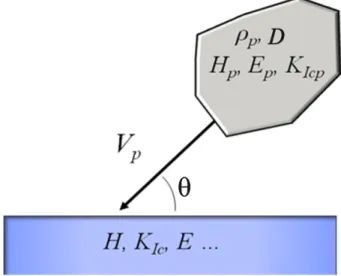
Figure 2.9: Illustration of the particle, target and operational parameters affecting SPE. ... 27
Figure 2.10: Typical SPE behavior for ductile (a) and brittle(b) materials [51]. ... 28
Figure 2.11: Proposed mechanisms explaining the ductile behavior of materials [53]. ... 29
Figure 2.12: Illustration of the effect of strain hardening ability on the erosion of ductile materials [61]. ... 31
Figure 2.14: Residual impressions left on fused quartz glass by the impact of 70 µm alumina
particles at a velocity of 45 m/s. ... 32
Figure 2.15: Schematic representation of lateral cracking following solid particle impact, adapted from [51]. ... 34
Figure 2.16: Illustration of the brittle to ductile transition for glass when the abrasive particle size is reduced from 127 µm (120 Mesh) to 9 µm (1000 Mesh) [70]. ... 36
Figure 2.17: SPE mechanism transition maps for (a) Glass and (b) a TiN coating [73]. ... 37
Figure 2.18: Fragmentation of a 300 µm sand particle upon impact with a tungsten carbide surface [76]. ... 39
Figure 2.19: Effect of particle properties on SPE mechanism transitions (adapted from [78]). . 40
Figure 2.20: Illustration of complex fracture processes in multiphase materials: (a) grain boundary cracking [82] and (b) intersplat cracking [83]. ... 42
Figure 2.21: Erosion of thick diamond films by large and high speed sand particles with interfacial (a) debonding [118] and (b) cracking [119]. ... 45
Figure 2.22: Pin-hole erosion crater in a thick diamond coating [120]. ... 46
Figure 2.23: Damage mechanism observed in EBPVD TBC: (a) Near surface cracking, (b) columnar compaction and (c) foreign object damage [156]. ... 47
Figure 3.1: PDCMS deposition system with dual magnetron configuration. ... 49
Figure 3.2: Types of SPE testers: (a) centrifugal-accelerator and (b) gas-blast [165]. ... 50
Figure 3.3: SPE testing chamber with windows and HEPA filter. ... 51
Figure 3.4: Sample and nozzle holder for SPE testing with retractable shutter. ... 52
Figure 3.5: Optical image of typical velocity calibration wear scars with the offset s indicated. ... 53
Figure 3.6: Double disk apparatus for time-of-flight evaluation of particle velocity. ... 54
Figure 3.7: Depth profile of the wear scars produced during a velocity calibration test. The measurement of s is indicated. ... 54
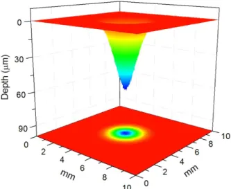
Figure 3.8: Alumina powder velocity calibration using a short nozzle and WD = 100 mm. .... 54 Figure 3.9: 3D topographical map of an SPE wear scar in c-Si. ... 55 Figure 3.10: Parameters and Gaussian fit used in numerical volume integration of SPE
experimental data. ... 57 Figure 3.11: SPE scar profiles on c-Si after exposure to 2 g of alumina powder at varying WDs. ... 58 Figure 3.12: Geometrical description of a Vickers type indenter [185]. ... 62 Figure 3.13: Depth-sensing indentation: (a) surface profile under indentation and (b) typical
load-displacement curve (adapted from [185]). ... 64 Figure 3.14: Load-displacement curve with the indicated areas representing the work of
indentation dissipated trough plastic means (Wp) and stored through elastic means (We). ... 67 Figure 3.15: Half-penny crack extending from a cube-corner indentation with the crack length c
indicated. ... 68 Figure 3.16: Step-like trench milled by focused ion beam to expose sample cross-section. ... 70 Figure 4.1: Erosion Examples of cracking under cube corner indentation: (a) half-penny
cracking with crack length c indicated and (b) lateral cracking. ... 79 Figure 4.2: Depth profiles of H and Er for all six target materials. ... 80 Figure 4.3: Depth profiles of plasticity for all target materials using (a) a cube corner indenter,
and (b) a Berkovich indenter. ... 81 Figure 4.4: Measured crack lengths versus applied load for half-penny crack evaluation. ... 83 Figure 4.5: Threshold loads for lateral (solid symbols) and radial (empty symbols) cracking as
a function of material index of brittleness. ... 83 Figure 4.6: Differential contribution of particle size to powder (a) volume (or mass) and (b)
area. ... 85 Figure 4.7: Differential micrographs of the alumina and glass powders before (a and c) and
Figure 4.8: Effect of SPE at Vp = 75 m/s on the alumina powder volumetric (a) and surface area (b) distributions, and on the glass powder volumetric (c) and surface area (d) distributions. ... 88 Figure 4.9: Changes in specific surface area as a function of the ratio Hp/Ht. ... 89 Figure 4.10: SPE rates for all six target materials using (a) alumina powder and (b) glass
powder as a function of Vp. ... 90 Figure 4.11: Residual impressions left on FQ glass by alumina particle impact at a velocity of
45 m/s. ... 91 Figure 4.12: Glass particle debris after impact at 45m/s on (a) BSG and (b) SLG... 91 Figure 4.13: Single impact tests using glass powder at an average velocity of 75 m/s for target
materials (a) BK7, (b) BSG, (c) FQ, (d) c-Ge, (e) c-Si and (f) SLG. ... 93 Figure 4.14: Single impact of glass particle with a velocity of 75 m/s on c-Ge. ... 94 Figure 4.15: Experimental ER versus predicted volume loss by the quasi-static SPE model
using (a) rigid particles and (b) deformable particles for Hp/Ht<1. Note that the tests on SLG with glass are represented by green half-empty triangles. ... 97 Figure 4.16: SPE velocity exponent as a function of yield pressure. ... 99 Figure 5.1: Partial-unload load-function used to obtain the coating mechanical properties. .. 106 Figure 5.2: Example, on a CrN coating, of cracking under cube corner indentation with crack
length c indicated. ... 108 Figure 5.3: 3D topographical map of an SPE wear scar in c-Si. ... 109 Figure 5.4: Volume loss measurement methodology: (a) Surface map of an SPE scar in c-Si
indicating the scanned area and the three line scans; (b) Parameters and Gaussian fit used in numerical volume integration illustrated on CrN coating SPE experimental data. ... 110 Figure 5.5: ER results of brittle bulk materials measured by the mass loss and volume loss
Figure 5.6: Effect of WD on SPE: (a) Erosion scar profiles and (b) Measured ER on c-Si at Vp = 45 m/s. ... 114 Figure 5.7: ER of c-Si and SLG as a function of fr. ... 115 Figure 5.8: Normalized ER of c-Si and SLG as a function of normalized inter-particle spacing. ... 115 Figure 5.9: SEM cross-sections of the coatings deposited on c-Si: (a) CrN-1, (b) TiN-2 and (c)
TiSiN-1. ... 117 Figure 5.10: Ht and Er for the three coatings deposited on c-Si as a function of hc/t. ... 118 Figure 5.11: KIC for the three coatings deposited on c-Si as a function of hres /t. ... 119 Figure 5.12: ER as a function of Vp for (a) the three coatings deposited on c-Si, and (b) TiSiN-1
deposited on various substrates with the substrate Er trend indicated. The erosion velocity exponents are in parenthesis in each legend. ... 120 Figure 5.13: Micrographs of the alumina powder before (a) and after (b) SPE testing at Vp = 60
m/s on TiSiN-1 deposited on c-Si. ... 121 Figure 5.14: Surface morphology in the middle of the wear scar after SPE testing at Vp = 60m/s
on (a) CrN, (b) TiN and (c) TiSiN. ... 123 Figure 5.15: Single impact morphology of (a) CrN at Vp = 60 m/s on, (b) TiSiN at Vp = 60 m/s,
(c) CrN at Vp = 120 m/s and (d) TiSiN at Vp = 100 m/s. ... 124 Figure 5.16: Effect of SPE at Vp = 60 m/s on the alumina powder volumetric (a) and surface
area (b) distributions. ... 125 Figure 5.17: Rp as a function of Ht/Er for all the tested coatings. ... 125 Figure 5.18: Correlation between ER and material parameters H, H/E and H3/E2. ... 126 Figure 5.19: ER as a function of surface Ht and Hp/Ht. ... 128 Figure 6.1: SPE velocity exponent as a function of yield pressure. ... 135 Figure 6.2: Effect of WD on wear scar uniformity. ... 136
Figure 6.3: Effect of sample masking by the QCM holder on ER of c-Si as a function of Vp. The inset presents the percentage of particles penetrating the mask as a function of Vp. ... 137 Figure 6.4: QCM natural frequency variation as a function of air pressure and illumination.139 Figure 6.5: Typical uncoated QCM sample mass loss as a function of total particle mass
impacting the surface. ... 141 Figure 6.6: Uncoated QCM SPE rates measured by the in situ and conventional techniques. ... 141 Figure 6.7: Cross-sectional SEM micrograph of the CrN monolithic coating. ... 143 Figure 6.8: Mass loss as a function of total particle mass impacting the surface for the CrN
monolithic coating: (a) complete curve and (b) detail of the beginning of the test. ... 143 Figure 6.9: Monolithic CrN SPE rates measured by the in situ and conventional techniques. ... 144 Figure 6.10: SEM micrographs of the Cr/CrN multilayer coating: (a) cross-section prepared by
FIB of coating before in situ testing, (a) cross-section prepared by FIB of coating after in situ testing, and (c) surface of coating after in situ testing. ... 146 Figure 6.11: SPE of a CrN/Cr multilayer coating: (a) mL vs. mp* , and (b) ER vs. m
p*. ... 147 Figure C.1: SPE protective system design cycle. ... 155 Figure A.1: SEM micrographs of, (a) as deposited CrN, (b) as deposited Cr-Si-N with CSi =
11.6 at.%, (c) eroded CrN film showing brittle SPE behavior (d) eroded surface of a CrN coating, and (e) eroded surface of a Cr-Si-N coating with CSi = 11.6 at.%. ... 175 Figure A.2: Bragg-Brentano XRD patterns for Cr-Si-N coatings with various CSi. ... 177 Figure A.3: Erosion rate (■), Hv (▲) and Hv3/Er2 (●) as a function of CSi. ... 180
LIST OF ACRONYMS AND SYMBOLS
Abbreviations
AISI American Iron and Steel Institute
ASTM American Society for Testing and Materials BK7 BK7 optical glass
BSG Borosilicate glass CAD Cathodic arc deposition c-Ge Single crystal germanium
CRIAQ Consortium for Research and Innovation in Aerospace in Quebec c-Si Single crystal silicon
CVD Chemical vapor deposition
DA Damage accumulation
DC Direct current
DLC Diamond-like carbon DSI Depth-sensing indentation
EBPVD Electron-beam physical vapor deposition EIPS Érosion par impact de particules solides
ERD-TOF Elastic recoil detection in the time of flight regime FCSEL Functional Coating and Surface Engineering Laboratory FEG Field emission gun
FEM Finite element modeling
FIB Focused ion beam
FQ Fused quartz glass
FQRNT Fonds de recherche du Québec - Nature et Technologies
FS Frequency shift
HEPA High-efficiency particulate air HVN Vickers hardness number ISE Indentation size effect
ISO International Organization for Standardization LDS Laser diffraction spectroscopy
MeN Transition metal nitride MS Magnetron sputtering
NSERC Natural Sciences and Engineering Research Council PC Protective coating
PDCMS Pulsed DC magnetron sputtering
PECVD Plasma enhanced chemical vapor deposition PVD Physical vapor deposition
QCM Quartz crystal microbalance
RF Radio-frequency
RQMP Regroupement Québecois sur les Matériaux de Pointe SEM Scanning electron microscope
SLG Soda-lime glass SPE Solid particle erosion SS410 AISI 410 stainless steel SZM Structure zone model TBC Thermal barrier coating
Ti64 Titanium alloy with 6% aluminum and 4% vanadium XRD X-ray diffraction
Symbols
3D Three-dimensional
(h/t)c Indentation depth over coating thickness ratio at which circular cracking occurs a Model based coefficient for hardness deconvolution
A Projected contact area
AE Area exposed to the flow of particles at.% Atomic percentage
B Fitting constant in Oliver and Pharr model
c Crack length
C0, C1, C2, etc. Fitting coefficients in area function cl Lateral crack length
cr Half-penny crack length CSi Silicon content
D Particle size
d Diagonal of the residual trace
dc Depth of the crack beneath the surface dd Spacing between diffracting planes
dg Grain size
E Young’s modulus
Ef Coating Young’s modulus
Ei Diamond Young’s modulus
Ep Particle Young’s modulus Er Reduced Young’s modulus
ER Erosion rate
ER* Normalized erosion rate ER90 90o erosion rate
ERconv Erosion rate evaluated by conventional mass loss technique ERQCM Erosion rate evaluated by QCM technique
f Natural frequency
F Fraction of particles which cut the target in an ideal manner f0 Crystal fundamental resonant frequency
fL Loaded natural frequency fr Particle feed rate
fu Unloaded natural frequency g Tabor material specific constant
G Toughness
H Hardness
h Indentation depth
H/E Elastic strain to failure H/KIC Index of brittleness H3/E2 Yield pressure
Hc Composite hardness hc Indentation contact depth hc/t Normalized contact depth
hf Fitting constant in Oliver and Pharr model Hf Actual coating hardness
Hi Intrinsic hardness
hmax Penetration depth at maximum load Hp Particle hardness
hres Residual indentation depth Hs Substrate hardness
Ht Target material hardness
Hv Vickers hardness
k Hall-Petch material constant
K Ratio of the vertical and horizontal forces applied to the particle tip Kc Fracture toughness
KE Kinetic energy
KIC Mode I fracture toughness KICp Particle fracture toughness
KICt Target material fracture toughness
L Lateral distance
L* Normalized inter-particle spacing
LL Lateral fracture threshold LR Radial fracture threshold
m Fitting constant in Oliver and Pharr model
M Meyer index
m0 Total coating mass per unit surface area before SPE testing ṁL Mass loss rate per unit of surface area
ṁp Particle mass feed rate in QCM testing mL Incremental mass loss per unit of surface area Mp Projected mass of particles
mp Particle mass
mp* Total particle mass impacting the exposed QCM surface mpi Incremental projected mass of particles
n Velocity exponent
nd Integer in Bragg's law
Nq Frequency constant for the AT-cut quartz crystal
P Applied load
p0 Mean contact pressure
Pm Maximum load during indentation PR Particle penetration ratio into the mask
q ISE Constant
r Radius
R2 Coefficient of determination
rd Radial distance between the wear scars and the rotation axis in double disk apparatus
Re Elastic recovery rn Nozzle inner radius
rp Particle radius
Rp Index of plasticity
RpBerk Index of plasticity measured with Berkovich indenter RpCC Index of plasticity measured with cube-corner indenter s Offset in double disk apparatus
S Material stiffness
Sm Material stiffness at maximum load
t Coating thickness
T* Generalized substrate temperature
TE Taux d'érosion
V Velocity
Vb Substrate bias during deposition Vcrit Critical velocity
Ve Volume lost per impact Vp Particle velocity
Vtotal Total volume loss after SPE testing
WD Working distance
Wirr Irreversible work of indentation Wp Plastic work of indentation
wt% Mass fraction
Wtotal Total work of indentation
z Depth of penetration during particle impact Z Measured depth of a given point in a scan Zf Z-Factor of a film
zm Maximum depth of penetration
Greek symbols
α Indentation fracture toughness constant β Factor depending on the indenter geometry
Δf Observed change in oscillation frequency of the crystal
Δm Mass loss
Δmp Mass of particles the sample is exposed to ΔV Elementary volume ring
Δx Scan lateral resolution
ε Strain
η Constant that depends on indenter geometry
θ Incidence angle
θd Diffraction angle
λ Wave length
μf Film shear modulus μq Quartz shear modulus ν Poisson coefficient
νi Diamond Poisson coefficient
ρ Density
ρp Particle density
ρq Quartz density
σ Stress
σstat Standard deviation
σy Yield strength (elastic limit)
χ Ratio between the length and width of the cut
ψ Cone half angle
LIST OF APPENDIX
CHAPTER 1
INTRODUCTION
Economic and technological progress as well as environmental concerns require that modern equipment be designed with ever more stringent performance criteria, frequently pushing components to the very limits of their capabilities. One major consequence of this increased demand on performance is that tribological deficiencies, such as lubrication breakdown, excessive wear and tribo-corrosion, can be significantly amplified, leading to unnecessary operational costs, decreased efficiency and premature failure. Because tribological processes result from the interaction of two or more bodies in relative motion in a particular environment, surface engineering can be used to confer to surfaces the high performance needed for demanding operational conditions. In this context, the design of the appropriate material system must be guided by an accurate understanding of the degradation mechanisms and the surface response to loading and deformation, frequently acting in synergy.
With sales of 12 Billion Canadian Dollars annually, the aerospace industry is the fourth in importance in the province of Quebec and the first in terms of exports with 80% of its production sold outside of the country. Its 235 companies employ 40,000 skilled workers and its average annual growth rate over the 25 years preceding 2010 was of 8.5% [1]. In order to maintain and increase this level of economic performance, new materials need to be developed to enhance overall aircraft efficiency through improved component lifetimes. One field of interest where research and development are needed is that of problems related to Solid Particle Erosion (SPE) of various aircraft components during the military or civilian missions. Sand or dust in the environment can cause significant damage to components such as helicopter rotor blades, compressor and turbine blades of jet engines, windshields or any exposed surfaces.
Research into SPE has been ongoing for more than 50 years but the protection of parts from the negative effects of SPE, by using surface treatment technologies, really started in the late 1980s in the USSR in order to protect military aircraft operating in the harsh environments of Afghanistan. Shortly thereafter, during the first Gulf War in the early 1990s, Great Britain’s Royal Air Force reported helicopter engine lifetimes of only 20 hours because of SPE-related performance degradation [2]. Since then, SPE has remained a pressing issue for the aerospace industry. In fact, Pratt & Whitney announced in 2004 that because of the premature wear by SPE of certain components, modifications would be made to the F135 engine of the new F35 Joint
Strike Fighter [3]. Finally, in 2010, the eruption of the Icelandic volcano Eyjafjallajökull led to one of the largest air travel shutdown since World War II because of the risks of visibility degradation by windscreen SPE and engine stalling through particulate ingestion and melting in the high temperature sections of the engine.
The damage to jet engines by SPE occurs primarily in the compressor section where the ingested particles follow trajectories which are strongly influenced by their size and speed, and the engine geometry (Figure 1.1).
Figure 1.1: Trajectories in a compressor flow path for (a) 2.5 μm particles and (b) 135 μm particles [4].
Combined to the complex geometrical shapes of the engine components, these lead to particles impacting surfaces at many angles of incidence: from grazing angle to perpendicular impacts. In fact, compressor blades typically show preferential erosion of the trailing edge where the particles impact with trajectories nearly parallel to the surfaces (Figure 1.2).
In order to minimize the ingestion of particles, filters and inertial particle separators are used but are not entirely efficient in stopping small sized particles from entering the engine. In addition, these components add weight to the aircraft while diminishing the overall performance of the engine. For these reasons, hard protective coatings (PCs) have been increasingly used in such applications in order to improve component lifetime while not adding significant weight.
The PC can drastically improve resistance to SPE by conferring to surfaces mechanical properties that are not possible to be attained with bulk materials. A full engine test conducted by the US Navy [6], in conjunction with the University of Cincinnati, showed the highly protective nature of the soviet developed SPE protective coatings based on a Ti/TiN multilayer structure. In that study, half of the compressor blades were coated and after more than 7 kg of ingested sand, these were relatively unworn when compared to the uncoated blades (Figure 1.3).
Figure 1.3: GE T64 jet engine compressor with half the blades coated with a TiN-based multilayer coating [7].
In the years since these first developments, many different coating systems in terms of architecture and composition have been proposed and studied. However, in order to select the optimal coating for particular operational conditions, it is necessary to understand the material loss mechanisms under SPE.
The surfaces of the components to be protected are generally metallic (stainless steel or titanium alloys) and the impacting particle will remove material predominantly through micro-cutting or ploughing. Conversely, the protective coatings are composed of much harder ceramic materials,
such as titanium nitride-based compounds, and will present much more complex erosion behaviors. In fact, it has been shown that brittle materials exhibit surface removal mechanisms closely related to fracture modes encountered during indentation (Figure 1.4) where different types of deformation (elastic and plastic) and cracking (Hertzian, radial and lateral) can occur depending on indenter geometry, applied load and surface properties. Consequently, transitions can occur between the different SPE material removal process depending on operational conditions and, in particular, on particle properties such as shape, size and brittleness.
Figure 1.4: Modes of fractures during indentation of brittle surfaces [8].
Because of the complex nature of SPE mechanisms, rigorous testing methodologies need to be employed and the effects of all testing parameters need to be fully understood. Unfortunately, most published studies on SPE protective coatings cannot be compared quantitatively because of a lack of methodological consistency.
In this PhD project, the importance of testing methodology will be addressed throughout in order to effectively study the SPE mechanisms of brittle materials and coatings. In this chapter, the context and the objectives of the project will be presented.
1.1 Context
From a very young age, I was greatly interested in all that involves aircraft and their use. Indeed, this passion led me to start my studies at the Collège Militaire Royal of St-Jean where I pursued a career in aviation. That adventure only lasted one year, but it nevertheless led me to complete a degree in Mechanical engineering at the École Polytechnique de Montréal with a concentration in aerospace engineering. Unfortunately, the importance given to materials science in the program was very small at the time and for that reason, I chose to work in the field of industrial mechanical engineering upon finishing my degree. For three years, I worked for SKF Canada Ltd, as an application and reliability engineer. One of my responsibilities was to design bearing and sealing systems for a variety of applications such as paper machine hot press rolls, wood chippers, train wheel assemblies, watercraft turbine impellers, etc. In the later part of my employment with SKF, I was also tasked in increasing machinery lifetimes and reliability for many different industrial clients through implementing predictive maintenance programs on site. In my capacity as a reliability engineer, I discovered a general lack of knowledge on tribological issues such as wear, friction and lubrication. This was not surprising to me because I had only spent about three or four hours of course time on tribology-related topics during all of my engineering studies. This lack of training seemed to be generalized in industry, as illustrated by the millions of dollars I have witnessed to be lost through the lack of proper tribological knowhow.
In an effort to reorient my career towards the field of protective coatings research, I was welcomed in the Functional Coating and Surface Engineering Laboratory (FCSEL) in January 2004 where my Master’s project was focused on the study of hard nanocomposite coatings, especially their mechanical properties. At first, I collaborated with Pawel Jedrzejowski, a recent PhD recipient, on an in situ growth study of TiN-based nanocomposite coatings which was later published in Applied Physics Letters [9]. Afterwards, I worked on the re-design and implementation of an increased capacity plasma enhanced chemical vapor deposition (PECVD) chamber and undertook the task of re-optimizing the deposition conditions of the TiN-based nanocomposite coatings.
In the subsequent years, I worked extensively on the development of the tribo-mechanical characterization capabilities of the FCSEL, by contributing to the grant application process,
investigating future equipment functionalities and purchasing and commissioning new equipment. Subsequently, I developed and implemented new indentation, scratch and erosion testing methodologies while training many users of the new equipment.
Being one of the most experienced users within the FCSEL, I also participated in numerous projects in collaboration with industrial (DAC aviation, DALSA Semiconductors, MDS Coatings Technologies, Novelis Inc., Pratt & Whitney, Bell Helicopter Textron, etc.), institutional (NRC, VAMAS, NPL, etc.) and academic (Aachen University, Institut national de la recherche scientifique, McGill University, Université de Mons, etc.) partners. These collaborations have led to five publications as co-author which are presented in Table 1.2.
Following my transfer to the PhD program in 2006, I was fully integrated into a new project in collaboration with several industrial partners and the Consortium for Research and Innovation in Aerospace in Quebec (CRIAQ) on the development and testing of protective coatings for aerospace applications. It was based on the needs of this collaborative project that I undertook my PhD research project.
1.2 Preliminary study on the effect of microstructure on the SPE of CrSiN
In a preliminary study that was accomplished in the context of this thesis, we studied the effect of the addition of silicon (Si) on the microstructure, mechanical properties and, more specifically, on the SPE resistance of thick CrN-based coatings. The article was published in Surface and Coatings Technology [10] and is presented in Appendix A.
This study was a continuation of the work done by the FCSEL’s post-doctoral fellow M. Benkahoul et al. [11] in which they demonstrated the increased hardness of CrSiN coatings when compared to the basic CrN coating. They showed that the maximum hardness (24 GPa) was attributed to solid solution hardening at a Si content of 2.3 at.%. As the silicon content increased, Si segregation to the grain boundaries occurred and the hardness dropped due to the formation of a weaker Si3N4 matrix.
In our study, we tested all the samples under the same SPE conditions (normal impact angle and a particle velocity of Vp = 70 m/s) and found that the addition of Si significantly improved the erosion resistance. In addition to using nanoindentation for hardness evaluation, we also used Vickers microindentation to evaluate the hardness at a similar scale as that found during a typical
SPE impact event. Interestingly, we concluded that the SPE results correlated much better with the microhardness values and that the coating with the highest microhardness also had the lowest erosion rate (ER). This suggested that the microstructure at the scale of the single particle impact volume of interaction played a large role in the erosion processes.
However, there were two additional findings that had the greatest impact on the orientation of the research in this thesis. First of all, it was found that circular cracking during Vickers indentation of hard coatings on ductile substrates was not representative of coating toughness. In fact, we found that ring cracking resulted from the inability of the coating to accommodate the important plastic deformation of the substrate. This meant that toughness could not be evaluated by indentation for hard coatings deposited on highly compliant ductile substrates. The second and most important finding was that the ERs showed a very strong dependence on the surface hardness. We believed that this finding could be a result of a mechanism based on a transition to micro-chipping as proposed by Shipway and Hutchings [12], but that was yet to be confirmed in the case of the studied PC.
These findings led to three interrogations which form the backbone of this thesis: i) what is the material loss mechanism of hard protective coatings during erosion; ii) what is the role of toughness on the erosion mechanism; and iii) what is the role of particle properties on the strong dependence of ER on the hardness of the target material?
1.3 Objectives
Based on the results from the preliminary study on the CrN-based coatings and on the needs of the collaborative projects with our industrial partners, the main objective of this PhD project is to investigate the material loss mechanisms during SPE of hard protective coatings, including nanocomposite and nanostructured systems. In particular, this research is focused on SPE using angular particles at relatively low velocities (below 100 m/s).
In order to accomplish the main goal of the project, the specific objectives are to: • Develop a robust methodology for the SPE characterization of coated systems;
• Investigate the effects of particle properties on the solid particle erosion mechanisms of brittle materials;
• Establish a systematic relationship between the mechanical properties of coated surfaces and their SPE behavior;
• Develop an in situ real time testing methodology to investigate SPE mechanisms of hard protective coating systems.
1.4 Thesis outline
Including this first introductory chapter, the thesis is divided into seven chapters and one appendix. In chapter 2, the important elements necessary to comprehend the content of this research project are reviewed, namely surface mechanical response, surface engineering techniques, nanocomposite coatings, solid particle erosion of materials and coatings. The following chapter (chapter 3) is an overview of the experimental techniques and methodologies that were used during the project for coating deposition, solid particle erosion testing, and microstructural and mechanical characterization.
In chapter four (Article 1), we study the effects of the particle properties on the SPE behavior of six brittle bulk materials using glass and alumina powders. First, we apply a robust methodology to accurately characterize the elasto-plastic and fracture properties of the studied materials. We then correlate the measured ER to materials’ parameters with the help of a morphological study and an analysis of the quasi-static elasto-plastic erosion models. Finally, in order to understand the effects of impact on the particles themselves and to support the energy dissipation-based model proposed here, we study the particle size distributions of the powders before and after erosion testing. It will be shown that tests using both powders lead to a material loss mechanism related to lateral fracture, that the higher than predicted velocity exponents point towards a velocity-dependent damage accumulation mechanism correlated to target yield pressure, and that damage accumulation effects are more pronounced for the softer glass powder because of kinetic energy dissipation through different means.
In the fifth chapter (Article 2), we study the erosion mechanisms for several hard coatings deposited by pulsed DC magnetron sputtering. We first validate a new methodology for the accurate measurement of volume loss, and we show the importance of optimizing the testing parameters in order to obtain results free from experimental artefacts. We then correlate the measured erosion rates to the material parameters measured by depth-sensing indentation. In order to understand the material loss mechanisms, we study three of the coating systems in
greater detail with the help of fracture characterization and a morphological study of the eroded surfaces. Finally, we study the particle size distributions of the powders before and after erosion testing in an effort to understand the role of particle fracture. It will be shown that the measured ERs of the coatings are strongly dependent on the target hardness and do not correlate with coating toughness. In fact, the material removal mechanism will be found to occur through repeated ductile indentation and cutting of the surface by the impacting particles and that particle breakup is not sufficiently large to influence the results significantly.
Studying SPE mechanisms of hard protective coating systems in detail has proven to be quite challenging in the past, given that conventional SPE testing is notoriously inaccurate due to its aggressive nature and its many methodological uncertainties. In the sixth chapter (Article 3), we present a novel in situ real-time erosion testing methodology using a quartz crystal microbalance, developed in order to study the SPE of hard protective coating systems. Using conventional mass loss SPE testing, we validate and discuss the advantages and challenges related to such a method. In addition, this time-resolved technique will enable us to discuss some transient events present during SPE testing of hard coating systems leading to new insights into the erosion process. Finally, in chapter 7, the work accomplished in this thesis will be summarized and the open questions and possible avenues of future research will be discussed. In the appendix, the article on the “Effect of microstructure on the erosion resistance of Cr-Si-N coatings” is presented. In the following Table 1.1, we present a list of the four publications directly related to this thesis, while Table 1.2 presents the five publications resulting from collaborations but not directly related to the project, and Table 1.3 presents a list of my invited talks, conference proceedings and other contributions.
Table 1.1: Peer reviewed publications resulting from this PhD project.
E. Bousser, M. Benkahoul, L. Martinu, J.-E. Klemberg-Sapieha «Effect of microstructure
on the erosion resistance of Cr-Si-N coatings». Surface & Coatings Technology, 203 (2008) 776.
E. Bousser, L. Martinu, J.-E. Klemberg-Sapieha «Effect of erodent properties on the solid
particle erosion mechanisms of brittle materials». Journal of Materials Science, Accepted, February 12th 2013.
E. Bousser, L. Martinu, J.-E. Klemberg-Sapieha «In Situ Real-Time Solid Particle Erosion
Testing Methodology for Hard Protective Coatings». Surface & Coatings Technology, Submitted, February 21st 2013.
E. Bousser, L. Martinu, J.-E. Klemberg-Sapieha «Solid Particle Erosion Mechanisms of
Hard Protective Coatings». Surface & Coatings Technology, Submitted, March 14th 2013.
Table 1.2: Peer reviewed publications resulting from collaborations.
S. Ligot, T. Godfroid, D. Music, E. Bousser, J.M. Schneider, R. Snyders «Tantalum-doped Hydroxyapatite Thin Films: Synthesis and Characterization». Acta Materiala, 60 (2012) 3435.
D. Li, S. Guruvenket, S. Hassani, E. Bousser, M. Azzi, J.A. Szpunar, J.E. Klemberg-Sapieha «Effect of Cr interlayer on the adhesion and corrosion enhancement of
nanocomposite TiN-based coatings deposited on stainless steel 410». Thin Solid Films, 519 (2011) 3128.
R. Snyders, E. Bousser, D. Music, J. Jensen, S. Hocquet, J.M. Schneider «Influence of the chemical composition on the mechanical properties of RF sputtered hydroxyapatite
coatings». Plasma Processes and Polymers, 5 (2008) 168.
R. Snyders, E. Bousser, P. Amireault, J.-E. Klemberg-Sapieha, E. Park, K. Taylor, L. Martinu «Tribo-mechanical properties of DLC coatings deposited on nitrided biomedical stainless steel». Plasma Processes and Polymers, 4 (2007) S640.
P. Jedrzejowski, A. Amassian, E. Bousser, J. Klemberg-Sapieha, L. Martinu «Real Time In-Situ Growth Study of TiN- and TiCxNy- Based Superhard Nanocomposite Coatings Using Spectroscopic Ellipsometry». Applied Physics Letters, 88 (2006) 71915-1.
Table 1.3: Invited talks, conference proceedings and other contributions.
Invited talks
E. Bousser, L. Martinu, J.-E. Klemberg-Sapieha, « Erosion Mechanisms of Hard
Nanocomposite Coatings ». Invited presentation, ICMCTF, 2012. San Diego, CA USA.
Conference proceedings, oral and poster presentations
E. Bousser, L. Martinu, J.-E. Klemberg-Sapieha, « In-situ Real Time Solid Particle
Erosion Testing Methodology for Hard Protective Coatings ». Presentation, ICMCTF, 2013. San Diego, CA USA.
E. Bousser, L. Martinu, J.-E. Klemberg-Sapieha, « Characterization and understanding of
the solid particle erosion mechanisms of hard coating systems ». Presentation, SVC conference, 2013. Providence, RI USA.
E. Bousser, L. Martinu, J.-E. Klemberg-Sapieha, «Multi-functional Analysis of Erosion
Resistant Coatings Using the OPX-MCT Apparatus». Presentation, CSM User Meeting, 2011. Boston, MA USA.
E. Bousser, S. Hassani, J.-E. Klemberg-Sapieha, L. Martinu, «Mechanisms of Erosion
Resistance in Brittle Materials and Coatings». Presentation, FCSE, 2011. Montreal, QC Canada.
E. Bousser, S. Guruvenket, S. Hassani, D. Li, M. Azzi, J.-E. Klemberg-Sapieha, L.
Martinu, «Protective TiN-based Nanocomposite Coatings for Tribological and Aerospace». Presentation, ICMCTF, 2011. San Diego, CA USA.
E. Bousser « Methodology for the Evaluation of Solid Particle Erosion Mechanisms in
Brittle Substrates and Coatings » Presentation, Final meeting CRIAQ – Project 1.20, 2010. Montreal, QC Canada.
E. Bousser « Erosion Performance of TiN/VN coatings » Presentation, Annual meeting
CRIAQ – Project 1.20, 2008. Montreal, QC Canada.
E. Bousser, M. Benkahoul, M. Azzi, L. Martinu, J.-E. Klemberg-Sapieha « Performance
of Cr-Si-N erosion resistant coatings for aerospace applications » Poster, ICAP, 2008. Churchill College, Cambridge, UK.
M. Benkahoul, E. Bousser, L. Martinu, J.-E. Klemberg-Sapieha « Microstructure, mechanical and tribological properties of Cr–Si–N coatings prepared by pulsed dual magnetron sputtering ». Poster, FCSE, 2008. Montreal, QC Canada.
E. Bousser, M. Benkahoul, P.Robin, L. Martinu, J.-E. Klemberg-Sapieha «Effect of
microstructure on the erosion resistance of Cr-Si-N coatings ». Presentation, ICMCTF, 2008. San Diego, CA USA. Silver Medal student award winner.
E. Bousser, J.-E. Klemberg-Sapieha « Erosion resistance coatings for aerospace ».
Presentation, INNO 08, 2008. Montreal, QC Canada.
E. Bousser « Erosion evaluation of coatings » Presentation, Annual meeting CRIAQ –
Project 1.20, 2007. Montreal, QC Canada.
E. Bousser, S. Hassani, J.-E. Klemberg-Sapieha « State of the art in erosion resistant
coatings » Presentation, kick-off meeting CRIAQ – Project 1.20, 2006. Montreal, QC Canada.
E. Bousser, P. Jedrzejowski, A. Amassian, L. Martinu and J.-E. Klemberg-Sapieha «
Growth study of TiN- and TiCxNy-based superhard nanocomposite ». Presentation, AVS Symposium, 2006. San Francisco, CA USA.
E. Bousser, P. Jedrzejowski, A. Amassian, R. Snyders, L. Martinu and J.-E.
Klemberg-Sapieha « Towards the application of nanocomposite coatings ». Poster, ICMCTF, 2006. San Diego, CA USA.
P. Jedrzejowski, A. Amassian, E. Bousser, L. Martinu and J.-E. Klemberg-Sapieha « In situ growth monitoring of nanocomposite TiN/SiN1.3 and TiCxNy/SiCN films using spectroscopic ellipsometry ». Proceedings, 48th Annual Technical Conference - Society of Vacuum Coaters, 2005, p 68-73.
CHAPTER 2
LITERATURE REVIEW
2.1 Surface mechanical response
The appropriate material’s selection for a given application must be guided by an accurate understanding of the intervening tribological process which results from the interaction of two or more bodies in a particular environment. The behavior of the system will be intimately related to the surface response to loading and deformation [13], which can generally be classified in three types:
1) Elastic deformation,
2) Plastic or permanent deformation, and 3) Fracture behavior.
2.1.1 Elastic response
It is common to characterize the mechanical behavior of a material by its strain (ε) response under an applied stress (σ) as illustrated in Figure 2.1 where the tensile behaviors of brittle and ductile samples are presented.
Figure 2.1: Schematic representation of brittle and ductile material behavior under tensile testing [14].
In the first portion of the curves, we observe the elastic response of the material which is characterized by being fully reversible and linear as defined by Hooke’s law with the material’s Elastic or Young’s modulus (E) as the proportionality constant so that,
ε
σ =E . (2.1)
In this regime, the material will fully recover its original shape once the load is removed.
2.1.2 Plastic response
Above a certain stress, plastic deformation occurs: the material no longer recovers and a residual strain is observed upon unloading. The stress above which plastic deformation is observed, which also corresponds to the stress where Hooke's law is no longer respected, is the proportionality limit. However, since it is impossible to determine this exact stress, in practice the transition from elastic to ductile behavior is defined by convention as the stress at which 0.2% of residual strain is observed. This stress is the material’s yield strength or elastic limit (σy).
In practice, it is not simple to obtain σy of a surface, in particular in the case of coatings or surface treatments. For that reason, the material strength is generally represented by the Hardness (H) which can be obtained by surface indentation. Hardness can be defined as a material’s ability to resist deformation under indentation, but unlike σy, it is a measure of the elastic and plastic deformations. Nonetheless, it has been shown by Tabor [15] to be directly related to σy by:
y g H = σ
(2.2) where g is a material specific constant (for metals, g ≈ 3). This equation has been found to be inaccurate for hard elastic materials, and a more accurate relationship between H and σy for elastic perfectly plastic materials was proposed by Hill [16] where:
− − + + = ) 1 ( 3 ) 2 1 ( 2 ln 3 2 3 2 ν ν σ σ y y E H (2.3) and ν is the material’s Poisson coefficient.
The strength of a material is a function of many parameters. At the atomic scale, bonding and interatomic distance are indicative of a material’s strength as can be seen in Figure 2.2, where
![Figure 1.3: GE T64 jet engine compressor with half the blades coated with a TiN-based multilayer coating [7]](https://thumb-eu.123doks.com/thumbv2/123doknet/2325916.30363/36.918.248.671.466.758/figure-engine-compressor-blades-coated-based-multilayer-coating.webp)
![Figure 2.1: Schematic representation of brittle and ductile material behavior under tensile testing [14]](https://thumb-eu.123doks.com/thumbv2/123doknet/2325916.30363/46.918.289.636.659.932/figure-schematic-representation-brittle-ductile-material-behavior-tensile.webp)
![Figure 2.4: Representation of the structure zone model proposed by Anders [36] showing the effects of deposition parameters on the coating microstructure](https://thumb-eu.123doks.com/thumbv2/123doknet/2325916.30363/54.918.154.772.507.913/figure-representation-structure-proposed-anders-deposition-parameters-microstructure.webp)
![Figure 2.7: Typical evolution of hardness as a function of material grain size [46].](https://thumb-eu.123doks.com/thumbv2/123doknet/2325916.30363/58.918.268.653.106.387/figure-typical-evolution-hardness-function-material-grain-size.webp)
![Figure 2.12: Illustration of the effect of strain hardening ability on the erosion of ductile materials [61]](https://thumb-eu.123doks.com/thumbv2/123doknet/2325916.30363/64.918.260.671.102.371/figure-illustration-effect-hardening-ability-erosion-ductile-materials.webp)

![Figure 2.16: Illustration of the brittle to ductile transition for glass when the abrasive particle size is reduced from 127 µm (120 Mesh) to 9 µm (1000 Mesh) [70]](https://thumb-eu.123doks.com/thumbv2/123doknet/2325916.30363/69.918.295.625.290.703/figure-illustration-brittle-ductile-transition-abrasive-particle-reduced.webp)
![Figure 2.21: Erosion of thick diamond films by large and high speed sand particles with interfacial (a) debonding [118] and (b) cracking [119]](https://thumb-eu.123doks.com/thumbv2/123doknet/2325916.30363/78.918.154.773.240.491/figure-erosion-thick-diamond-particles-interfacial-debonding-cracking.webp)