A simple approach for the design of steel and composite
sway building frames
René MAQUOI 1 and Jean-Pierre JASPART 2 Department M&S
Institute of Civil Engineering University of Liège
Chemin des Chevreuils, 1 B 4000 Liège (Belgium)
___________________________________________________________________________
Abstract
The Merchant-Rankine approach is a practical design procedure which allows to predict the
ultimate resistance of sway steel building frames with rigid structural joints. In the present paper the background and the traditional field of application of the Merchant-Rankine formula are first
described. Its extension to the design of steel frames with so-called semi-rigid joints is then presented and justified. Finally its application to steel-concrete sway composite building frames is
investigated and first conclusions of this work are drawn.
Key words: sway frames, stability, semi-rigid joints, composite construction.
___________________________________________________________________________
1.
General
Low-rise steel buildings can often be idealised as a series of two-dimensional frames, each of which
resists loading in its own plane primarily by flexure. Plastic theory provides an economical basis for the design of such frames when these are fabricated using shapes of uniform cross-section. In
rigid-plastic analysis it is assumed that when the collapse mechanism is formed, the deformations experienced by the structure are insufficient to alter significantly the equations of equilibrium. The
resulting method of analysis is straightforward to apply and is especially appropriate therefore for low-rise buildings.
It is generally agreed that first-order rigid-plastic hinge theory may be applied directly to the design
of frames up to three storeys, as far as the estimation of the collapse load is concerned. Of course the limit of three storeys is just a statement, that is valid in most - but not all - the situations met in
design practice, when the columns are neither too slender, neither too flexible. Some criteria exist which allow for using the first-order plastic hinge theory. For instance, it is required in (ECCS 1984)
that (figure 1):
a) The ε factor, defined as ε=l N /EI is not larger than 1,6 in all the columns; b) No plastic hinges develop between column end points;
c) r r
I
r ≤Q /10P
ψ , a inequality which means approximately that the additional storey shear
produced by the axial forces in the columns due to sway is smaller than 1/10 of the storey shear Qr =Hr +ψoPr and therefore may be considered negligible.
In above expressions, the symbols have the following meaning:
I r
ψ : Column-slope of storey r calculated based on the stress resultants at collapse obtained by
a first-order plastic hinge analysis;
o
ψ : Initial out-of-plumb;
Hr : Total sum of factored external horizontal working loads above storey r;
Pr : Total sum of factored vertical working loads above storey r ;
l : Column depth;
EI : Column flexural stiffness;
N : Factored axial working load in the column.
The restriction ε≤1.6 and the requirement of no plastic hinges between column end-points are necessary to preclude local instability of highly compressed slender columns. Above restriction (c)
makes the commonly termed P−∆ effect negligible.
In order to help the designer in his daily work, several studies have been aimed at giving yet more simple limits within which second-order effects can be neglected in plastic analysis of plane
single-storey, single bay, pinned base frames (ECCS 1991). The limits are applicable to such topological frames only, where vertical forces can be treated as distributed loading along the beams and/or
rafters as is usually the case in building structures.
In Eurocode 3 (Eurocode 3 1992), the field of application of the first order rigid-plastic theory is limited to structures such that VSd /Vcr ≤ 0.1 where VSd and Vcr are respectively defined as the
design vertical load acting on the frame and its elastic critical instability load. This criterion is used in Eurocode 3 as a boundary when classifying a frame as sway (P-∆ effects to be considered) or non-sway (P-∆ effects to be disregarded); it is further discussed in Section 4.
For multi-storey frames of many storeys, first-order plastic hinge analysis is no more permitted and modifications are to be brought to assure safety, because of two different effects:
b) Frame collapse may be due to instability, which is likely to prevent the structure from reaching the ultimate plastic capacity provided by the first-order plastic hinge theory.
Then a more refined structural analysis must be contemplated. In contrast to the concept of plastic
hinge, where the material yielding is assumed to concentrate into a single cross-section, the one of plastic zone accounts for the actual spreading of material yielding in the close vicinity and on both
sides of the fully yielded cross-section. The ultimate strength theory, based on the concept of plastic zones, requires the use of very sophisticated non-linear computer programs. It provides only a slight
change in the results, compared to a second-order plastic hinge theory. Therefore the latter is very much preferred and numerous proposals have been made that are aimed at adopting the rigid-plastic
analysis to allow for the reduction of ultimate load capacity due to both change in geometry and frame instability.
Compared to rigid joints, semi-rigid beam-to-column joints would result in a larger flexibility of the
frame, and consequently in a larger sensitivity to global frame buckling. Therefore it is generally agreed that multi-storey frames should make use of rigid joints. Should the joints be semi-rigid
anyway, then, at the beam-to-column interface, the plastic capacity of the joint - which is generally less bending resistant that the beam section - must be substituted for the plastic bending resistance of
the beam.
Plastic analysis may be utilised in the global analysis of structures or of their elements provided that
plastic hinge mechanisms be able to develop really. Therefore the available rotation capacity of both structural shapes and joints cannot be less than the rotation capacity required by the formation of
Ideally it is desirable to obtain as close an estimate as possible of the true collapse load factor. One
of the easiest ways to do so is known as the Merchant-Rankine formula. The latter provides an approached value of the ultimate load factor, computed based on the sole knowledge of both the
first-order rigid-plastic limit load factor and the elastic critical buckling load factor. The relevant relation is quite similar to the one established for the axial resistance of a single eccentrically loaded
column. Therefore column stability and frame stability are examined in turn in this respect.
2.
Column buckling by excess of bending in the loading plane
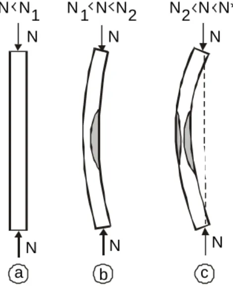
Let us consider a slender pin-ended column made of a compact section, which is eccentrically
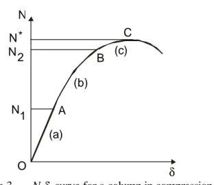
loaded by a growing compressive force (figure 2.a). Its load-transverse deflection response is the one plotted in figure 3. At the very first beginning, the column bends elastically till the material yield
stress is reached in the most compressed fibre at mid-length (point A in figure 3). When the load is further increased, the plastic zone progresses in depth and extends over a certain region close to
mid-length (figure 2.b). Possibly the direct stress on the convex side may yield too, especially when the load eccentricity is small (figure 2.c). The load-deflection curve then grows non-linearly beyond
the elastic region OA; the more extended the yielded zone the more the flexural stiffness of the column is reduced, and the lesser the slope of the N-δ curve. A neutral state of equilibrium is reached when the bending resistance is exhausted (peak C in figure 3); the structural stability is no more warranted and the column is prone to collapse.
Though the neutral equilibrium is preceded by stable plastic strains, instability is well of concern at
internal resistance and external forces.
Because the determinative cross-section - the one located at mid-span - is actually subject to bending and compression, it is not able to exhibit the full bending resistance Mp of the section and to
develop an ideal notional plastic hinge.
Usually elastic column buckling approach assumes that the ultimate strength limit state is governed by the onset of material yielding in the most compressed fibre of the critical cross-section. That results
in the well-known secant formula. Such a solution is not fully satisfactory because it disregards any plastic strength reserve. No doubt indeed that the latter exists with a magnitude, which depends on:
- The relative eccentricity of the compressive force; - The shape of the column cross section;
- The type of material, especially reflected by the stress-strain response curve.
A rather simple way of accounting for such a strength reserve is based on the assumption that a plastic hinge develops all a sudden in the determinative section at mid-length of the column, when the
moment loading amounts the relevant reduced plastic bending resistance MpN allowing for the axial
force N (Vogel 1965). Then the column is no more stable because transforming into a plastic
mechanism; the corresponding collapse load N* is drawn from equilibrium condition at mid-span:
pN * M d (e N + )= (1)
of above assumption - sudden onset of the plastic hinge -, the total deflection
(e + δ) can be computed elastically according as the well-known expression :
[
1 N*/NE]
/ e − = +δ e (2)where NE is the elastic critical column buckling load. A further simplification consists in disregarding
the influence of axial force on the plastic bending capacity of the section (Ligtenberg 1965). Then
Eq. (1) writes simply:
p
E] M
- N*/N 1
N*e/[ = (3)
Another reasoning bases on a simple rigid-plastic design approach, according to which elastic strains
as well as second-order effects are fully neglected. Collapse should occur when the bending moment produced by the eccentrically applied axial force of magnitude Nl reaches the full plastic bending
resistance Mp of the section, wherefrom:
p l e M
N = (4)
Formulae (3) and (4) result in:
) N /(N N N N* = E l E + l (5.a) or:
This latter expression is commonly known as the Rankine formula (Rankine 1866). It allows for a
fairly good assessment of the ultimate load N* when the loading eccentricity is not too large. The attractiveness of above approach lies in the theoretical background it gives to a similar expression,
which was suggested to assess the detrimental effect of the buckling by divergence on the collapse load of sway multi-storey frames (Merchant 1954).
Ultimate loads computed in accordance to (5.b) for I and H sections subject to strong axis bending
are found in quite satisfactory agreement with those provided by a refined approach on the one hand (Vogel 1965) and exact solutions on the other hand (Jäger 1937), provided the loading eccentricity
be not less than four times the central core radius.
3.
Global frame buckling
By nature a framed structure is initially geometrically and materially imperfect. More especially the
columns exhibit an unavoidable out-of-plumb. When such a frame is subject not only to gravity loads but also to horizontal forces (wind loads, for instance), it deflects horizontally since the very first
beginning of the loading. Horizontal drifts provide lever arms to gravity loads wherefrom second-order bending moments; the frame response in terms of load-displacement relationship is
non-linear. The carrying capacity is given as the peak of the corresponding curve, where a neutral state of equilibrium is reached. Because most of the vertical forces acting onto the frame are gravity
loads, their magnitude does not decrease while sway increases; therefore the peak load is the ultimate load.
What is said here above implies that the flexural stiffness of all the structural elements composing the frame is not substantially changed when the loading magnitude is progressively increased. That is
mostly in contradiction with the true frame behaviour. In more than once statically indeterminate frames plastic hinges indeed develop usually prior to complete loss of frame stability. They reduce
the flexural stiffness of the structural elements - and therefore of the global frame - and change the bending moment distribution. Material yielding and more especially onset of plastic hinges result in a
progressive deterioration of the frame stability.
Most of the complexity in sway frames arises because of the possible too large drift when lateral load is applied. Let us consider, as an example, the four storeys frame of figure 4, which is loaded
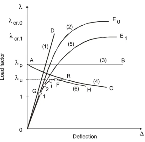
by concentrated gravity forces at mid-span of the beams and wind forces applied horizontally at each storey. All the loads are increased proportionally by means of a load factor λ. The qualitative load factor - drift behaviour is plotted in figure 5:
- Straight line (1) is the linear elastic relation, in which instability, change of geometry as well as
material yielding are ignored; it is the first-order elastic response.
- Curve (2) results from a second-order elastic analysis, where the material is assumed indefinitely
elastic and due consideration paid to changes in geometry (P-∆ effects); its asymptotic load is measured by the elastic critical buckling load factor λcr,o because collapse results from frame
instability.
- Horizontal line (3) represents the first order rigid-plastic collapse load factor λp ; material
yielding is accounted for while change in geometry is disregarded.
- When allowance is made for change of geometry in the rigid-plastic theory, descending curve
- In an elastic-plastic analysis conducted on the initial frame geometry (first-order analysis) plastic hinges develop successively; once the first hinge has developed (point 1 on curve (2)), the
load-deflection response follows the second-order elastic curve branch (5) relevant for the frame fitted with a hinge at the location of the yet occurred plastic hinge. Each time an additional hinge
develops, the frame stiffness decreases accordingly and the behaviour adapts similarly. The frame response follows the curve (6) and peaks at load factor λu.
- Should the change of geometry be now accounted for, then a continuous curve slightly lower than curve (6) would be obtained. In addition following additional effects should be included:
a) Spreading of yielding according as plastic zones instead of plastic hinges; b) Influence of possible residual stresses and initial geometric imperfections;
c) Material strain hardening.
The two first of these factors tend to lower the peak load whereas strain hardening tends to
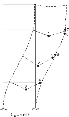
raise it. On balance, there is a tendency for a conservative estimate of the peak of the true load-deflection curve. The collapse mode of the frame illustrated in figure 4 is the one indicated on
figure 6; the numbers show the order of onset of plastic hinges.
The process according to which the flexural stiffness deterioration contributes in controlling the actual ultimate load (Wood 1958) helps very much in understanding the interaction between hinge
onset and instability. Therefore it is useful to comment somewhat more.
The elastic critical frame building load factor is termed λcr,o. It will not be reached if one or more
plastic hinges occur(s) at load level(s) lower than λcr,p. Let us assume that a first plastic hinge occurs
rotate, while being subject to a constant bending moment equal to the plastic resistance of the relevant section. Provided the rotation does not reverse, this section shall henceforth no more
contribute the flexural stiffness of the frame. Thus, once this plastic hinge is formed, the frame has become more flexible and its elastic critical frame buckling load factor decreases from λcr,o down to
λcr,1. The latter value can be computed, similarly as λcr,o, after substitution of the plastic hinge by a
free hinge. Above reasoning process can be repeated at each time an additional plastic hinge
develops in the structure.
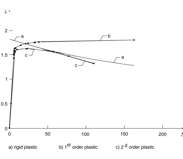
To which extent the stability may be deteriorated is highlighted by the example of figure 4. For this frame, the first-order rigid-plastic mechanism should require ten plastic hinges and the relevant
plastic load factor would be λp = 1.79. On the other hand, the elastic critical buckling load factor of the original frame is λcr,o = 16,92; this large value should let expect that second-order effects can
be disregarded in service conditions (λ = 1). Values of λcr,i of the frame where some plastic hinges
- in number i - have occurred are given in figure 7.
When the load factor is progressively increased, plastic hinges successively develop in the structure
with the result of a decrease in the elastic critical load factor of the evolutive frame.
Understandably the onset of only some of the ten plastic hinges may be sufficient to deteriorate the frame flexural stiffness to such an extent that the decreasing elastic critical load multiplier λcr,i
overtakes the increasing load factor λ. That will prevent the frame from reaching the rigid-plastic first-order collapse load. For the building structure represented in figure 4, plastic hinges occur
can be concluded that the loss in strength due to second-order effects, when compared to first-order plastic collapse load (figure 8), amounts approximately: (1.79 - 1.63)/1.79 = 6%.
Of course the number of plastic hinges that are yet formed when collapse occurs depends very much
on the global relative slenderness of the frame. Should the latter be small enough - what would mean that the P-∆ effects can be disregarded - then there is no significant interaction between yielding and instability and the collapse load factor is close to λp.
4. Merchant-Rankine-Wood formula
It has been postulated (Merchant 1954) that Eq. (5.b), established for a column, has a general
validity and can be generalized with a view to assess the ultimate buckling load of elastoplastic sway frames. Although suggested by Merchant as a purely empirical formula, it has been shown (Horne
1963) to have some degree of theoretical justification. Another demonstration of this validity was provided based on theoretical considerations (Witteveen 1975).
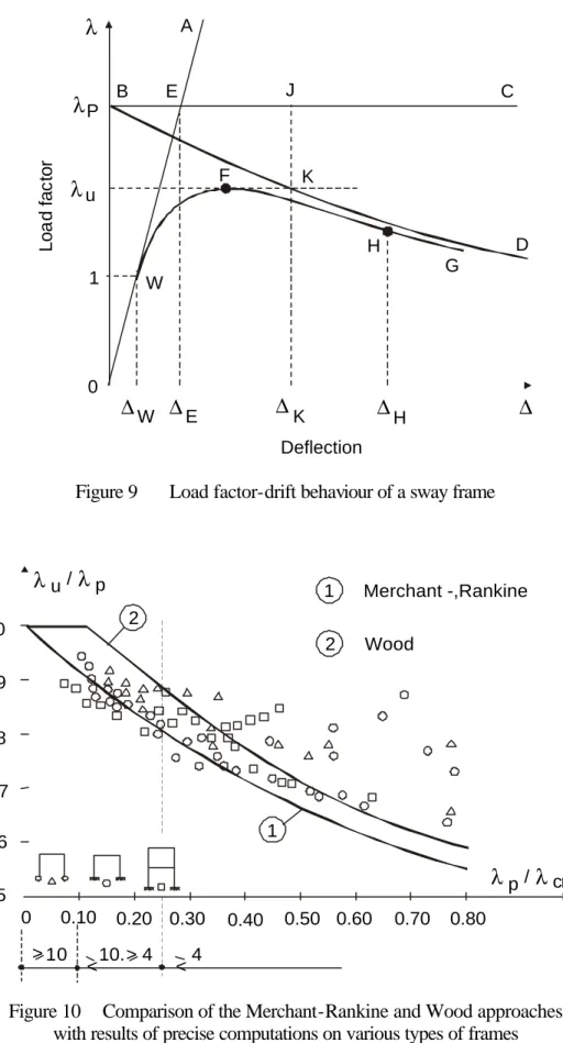
Using the concept of load multiplier introduced in previous section, Merchant's basic idea leads to
write : cr p u 1 1 1 λ λ λ = + (6.a) or: ) / ( 1 p cr p u λ λ λ λ + = (6.b) with :
λp : first-order rigid-plastic load factor ;
λcr : elastic critical frame buckling load factor (equal to λcr,0 in Section 3).
All the forces composing the frame loading are thus assumed to increase proportionally indeed. Eq.
(6.b) is thus likely to account for the interaction between elastic critical buckling load (line OA in figure 9) and the first-order rigid-plastic load multiplier (line BC in figure 9).
According to the limit states design philosophy, the reliability of a specified frame at the ultimate limit
load is warranted when the ultimate load multiplier λu is at least equal to the design load factor γF,
the value of which is given in codes or standards. Because collapse of unbraced multi-storey frames
involves interaction between elastic buckling and onset and spreading of material yielding, λu is also
termed elasto-plastic frame buckling load factor.
Should the frame be very stiff against sides-way, then λcr is much larger than λp with the result of a
low (λp/λcr) ratio. Then a minor influence of the geometric second-order effects is expectable; the ultimate load will be close to the first-order rigid-plastic load.
In contrast, a flexible sway frame is characterised by a large value of the (λp/λcr) ratio. It shall
collapse according to a nearly elastic buckling mode at a loading magnitude, which approaches the elastic bifurcation load.
Merchant and his collaborators have analysed a large number of single bay frames, with one or two
are plotted in figure 10 and compared to those drawn from Eq. (6.a.), which is most often found safe. Comparisons with accurately calculated elastic-plastic failure loads (Salem 1958) and with
experimental results (Low 1959) show that Eq. (6.a) gives a reasonable estimate of failure loads for multi-storey frames with significant side loads, and a conservative estimate for multi-storey frames
with side loads, which are small compared to simultaneously applied vertical loads. That is illustrated in figure 11 which shows values of the failure load factor λu/λp derived from tests on 3,5 and 7
storey model frames (Low, 1959); the lower straight line AB represents the Merchant-Rankine formula and it is seen that all experimental points lie on or above this line. In figure 11, the radial
straight lines are quoted in values of λcr/λp.
Similar comparisons (Ariaratnam 1959) and (Zandonini 1991) show also that Eq. (6.a) provides generally an unsafe estimate of the failure load factor for multi-storey frames with a very large ratio
of horizontal to vertical loads; such a loading pattern is not common in practice.
In another study (Jaspart 1991), the relative accuracy of the Merchant-Rankine formula has been linked to both the ratio of horizontal to vertical loading and the type of first-order plastic mechanism.
It is worthwhile stressing that a panel mechanism develops mainly in frames subject to predominant side loads. Usually such frames do not fulfil the design requirements under non factored loads and
the Merchant-Rankine approach is of course not applicable in such conditions. Design studies (Anderson 1982) show however that Eq. (6.a) provides a safe estimate of the non-linear
elasto-plastic failure load, λu, for frames which satisfy a serviceability limit of 1/300 on sway, and are
Strain hardening tends to raise plastic hinge values above the values calculated from the yield stress. Therefore most practical frames of only a few storeys in height attain at collapse a load at least equal
to the theoretical rigid-plastic collapse load. When the ratio λcr/λp is commonly greater than 10, the
residual stiffness due to material strain-hardening more than compensates for the effects of changes
of geometry. A detailed study has been made of the effects of strain hardening (Horne et al , 1967).
In addition to the effect of strain hardening, it is found that even a small amount of stiffness from cladding is sufficient to compensate for changes of geometry.
To allow in a general treatment for the minimum benefit effects to be expected from both
strain-hardening and cladding, a modification of the Merchant-Rankine formula was suggested (Wood 1968 and 1974) in the simple form :
p cr p p * u ) / ( 9 . 0 λ λ λ λ λ = + >/ (7)
in the range λcr/λp≥ 4. This formula is represented by respectively the lines CD and AC in figure
10. Wood has recommended that his formula should not be used in practice for values of ratio
(λcr/λp) lower than 4 and that a second-order elastic-plastic analysis is carried out in this range.
When λp/λcr ≤ 0.1, λu is limited to λp, what means that the frame can be designed according to
the simple first-order plastic hinge theory. A clear and immediate relationship may be established between this criterion and the one, expressed in Section 1, which limits the application of the
The use of Eq. (7) is commonly restricted to frames in buildings, in which the cladding has not been
specifically designed as a main structural element and provided that (ECCS 1984): 1) The frame is braced perpendicular to its own plane;
2) The average bay width in the plane of the frame is not less then the greatest height of one storey; 3) The frame does not exceed 10 storeys in height;
4) The sway at each storey, due to non factored wind load does not exceed 1/300 of the storey height;
5) The capacities of the columns are based on the onset of yielding in extreme fibres;
6) λp is calculated with storey shears given by Qr = Hr + ψoPr, the terms being defined in above
Section 1; 7) λcr/λp≥ 4.
For bare frames, or for frames in which specific account is taken of the cladding's structural strength
or stiffness, the collapse load factor λu may be calculated by Eq..(6.b) provided that conditions (1) - (7) are also satisfied.
It is generally considered that above criterion (3) is abnormally restrictive. It is nevertheless kept as a
safeguard because a lack of information in this respect.
When using such a simplified design approach as the Merchant-Rankine-Wood formula, it is usually not necessary to care for the buckling check of individual columns between the storeys. It was
buckling of the global frame. The latter is thus governed by the gravity loads, which are distributed on all the beams of each storey. Indeed checkerboard load distributions produce beam deflections,
which are not consistent with the sway buckling mode of the frame. However a local checkerboard loading is likely to be determinative for the column of the upper storeys.
5.
Generalisation to frames using semi-rigid joints
The Merchant-Rankine-Wood approach thus substitutes the complex straightforward assessment of the ultimate load factor λu by the more simple computation of both the elastic critical buckling load
λcr and the first-order rigid plastic load factor λp. Methods allowing for the appraisal of λcr and
λp are available for a long time for frames using rigid connections (Jaspart 1991).
Compared to rigid joints, semi-rigid joints would result in a larger flexibility of the frame and
consequently in a larger sensitivity to global frame buckling. Though it is generally agreed that multi-storey frames should preferably make use of rigid joints, the generalization of the
Merchant-Rankine-Wood approach to frames using semi-rigid joints may appear questionable.
A so-called semi-rigid joint exhibits a behaviour between that of a rigid joint, which requires a full rotational continuity, and a pinned joint, which is not able to transfer bending moment. There are
several sources of deformability taking place mainly in the connection properly and in the column web panel. For practice purposes, they are usually not discriminated and the resulting global
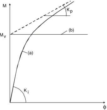
behaviour is then characterized by a single response curve plotting the joint moment M versus the relative rotation φ between both column and beam axes. Actually such a curve is non linear; it can normally be described by the initial stiffness Ki, the strain-hardening stiffness Kp and the
pseudo-plastic moment capacity Mv (fgure. 12 - curve a). Because a semi-rigid connection may be a
weak point, it is a possible location for a pseudo-plastic hinge. The question arises whether the
actual joint behaviour presents some similarity with a compact section subject to bending. It may be answered positively having in mind that the concept of plastic hinge is, for its own, an idealisation of
the pure flexural behaviour of a section. Therefore it is quite justified to refer to a rigid-plastic joint behaviour, which is fully described by the magnitude of above pseudo-plastic moment Mv (fgure 12
- curve b). Indeed the initial stiffness of the joint is not likely to influence the λp load factor as far as
a first-order plastic hinge theory is concerned. In addition strain-hardening in the joint behaviour is
accounted for, similarly to material strain-hardening, by means of the correction factor 0.9 introduced in Eq. (7) yet.
Of course the plastic moment resistance to be used at the beam end shall be chosen equal either to
the plastic capacity Mpb of the beam or to the pseudo-plastic moment Mv of the joint, according to
which is the lesser; indeed the plastic hinge may occur either in the beam or in the joint.
The assessment of λp is a rather tedious task for multi-storey frames. Should the designer not have
access to adequate computer programs, then a simplified procedure may be used alternatively (Jaspart 1991).
The elastic critical frame buckling load factor refers to the linear elastic analysis and thus to the
bifurcation theory of frame buckling. The beam-to-column joints shall consequently be characterized by their initial stiffness Ki (figure 12). Of course above factor can be determined based on a
preliminary design is largely facilitated by following procedure (Jaspart 1988 and 1991):
a) The actual complete structure with semi-rigid joints is transformed into an equivalent substitute
single bay frame with rigid joints; and then, either :
b) A Grinter frame is derived from the equivalent substitute frame with rigid joints; c) An equivalent Grinter frame is determined aimed at the stiffness-distribution method;
or
b) Simplified procedures for the assessment of λcr, which are available in the literature, are applied to the single bay frame with rigid joints.
Of course, step (a) is by-passed when the frame has rigid joints.
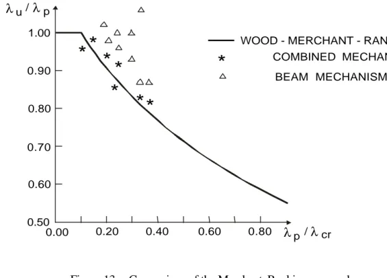
Comparisons between the Merchant-Rankine-Wood formula and results of numerical simulations
for multi-storey frames with semi-rigid joints are presented in figure 13 (Jaspart 1988 and 1991). They confirm that, when used within its application range, the Merchant-Rankine-Wood formula
gives:
- A good estimate of the collapse load factor as far as the collapse mechanism is a combined
one;
- A slightly conservative estimate of λu when a partial beam mechanism is governing.
6.
Generalisation to composite frames
More recently the generalisation of the Merchant-Rankine and Wood approaches to sway steel-concrete composite building frames has been contemplated at the University of Liège (Majkut
composite structures to sway frames" funded by ECSC (European Commission for Steel and Coal) and in which several European partners are also involved (Universities of Aachen and Bochum in
Germany, ProfilARBED in Luxembourg, CTICM in France, University of Pisa and European Joint Research Centre in Italy and LABEIN in Spain).
The validation of the Merchant-Rankine and Wood approaches is achieved through comparisons
with numerical simulations carried out with the non-linear finite element program FINELG (FINELG 1999) developed at the University of Liège. The results of such numerical simulations is illustrated in
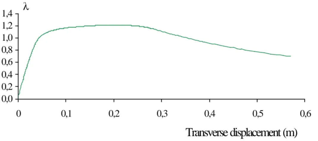
figures 15 a-c in the case of a three-bays and four-storeys frame (figure 14) with steel columns and composite floors (reinforced floor slab connected by means of shear studs to a steel I profile), which
is loaded as indicated in table 1.
In the preliminary study (Majkut 2001), the numerical simulations have been performed on a parametrical basis, by varying the values of the two following parameters, which significantly
influence the frame behaviour: the rotational stiffness and the resistance of the column bases and the steel grade.
The diagrams presenting the results of the comparison between two series of numerical simulations
and the Merchant-Rankine approach are shown in figures 18 and 19 respectively. As the strain-hardening effects have not been taken into consideration in the FEM analysis, only the
Merchant-Rankine curve is reported in figures 18 and 19.
numerical simulations is seen to be rather good (maximum difference of 6%). Hence as a first preliminary conclusion, the level of interaction between instability and plasticity effects in composite
frames seems, roughly speaking, to be similar to the one met for steel frames.
However, from a closer examination of the results, it appears that the application of the Merchant-Rankine formula in combination with the fully elastic critical instability load factor λcr,uncracked leads in
most cases to an unsafe evaluation of the ultimate resistance of the frames. The fully elastic critical instability load factor has to be considered as the one obtained by assuming than both constitutive
materials (steel and concrete) behave in a fully elastic way and, in particular, that the concrete remains uncracked. The results of the computations based on this assumption are identified as
“uncracked” in figures 18 and 19.
This conclusion is in direct contradiction with what is observed for steel frames (see Sections 4 and 5), at least as long as beam and combined yield mechanisms are associated to the rigid-plastic load
factor λp of the frames, what is the case for the composite structures considered in the parametric
study.
In fact it seems that this discrepancy results from the empirical nature of the Merchant-Rankine
approach. This one has been developed for sway steel building frames where the loss of stability is related to the onset of plastic hinges in the structure while, in composite structures, another source of
deformability exists and develops well before the apparition of the first plastic hinge: the cracking of the concrete.
This effect, which is specific to composite construction, tends to increase the lateral deflection of the frame and consequently to amplify the second-order effects and reduce the ultimate resistance of the
frames. In other words, for an equal number of hinges formed at a given load level in a steel frame and in a composite frame respectively, larger lateral displacements will be reported in the composite
one.
In order to integrate this detrimental effect into the Merchant-Rankine approach, Majkut suggests to substitute the critical “uncracked” instability load factor λcr,uncracked by a “cracked” one, noted
λcr,cracked . This modification allows to increase the calculated ultimate load factors, as seen in figures
18 and 19, and therefore to eliminate, or at least reduce, the unsafe character of an “uncracked”
Merchant-Rankine approach.
Further studies on different types of structures and loading conditions would be required to validate the presented approach. This work is planned for this academic year at the University of Liège.
7.
Conclusions
In the present paper, the scope of the well-known Merchant-Rankine approach is extended to steel building frames to semi-rigid joints, while its initial field of application was limited to frames with rigid
joints. In a recent study, its generalisation to composite construction has been considered. From preliminary investigations carried out at the University of Liège, this extension may reasonably be
contemplated, but further validation works are required before a practical application in design offices.
8. References
Anderson, D., Lok, T.S. and Wood (1982), R.H. “Studies of the Merchant-Rankine formula”,
Research Report CE 12, University of Warwick.
Ariaratnam, S.T. (1959). “The collapse load of elastic-plastic structures”, Ph.D. Thesis, University
of Cambridge.
Bernuzzi, C. and Zandonini, R. (1991). “Stability of partially restrained sway frames”, Annual
Technical Session and Meeting of the SSRC, Chicago, U.S.A., April 15-17, pp. 449 - 462.
ECCS (1984). “Ultimate Limit State Calculation of Sway Frames with Rigid Joints”, ECCS
Publication n° 33, Brussels.
ECCS (1991). “Practical Analysis of Single Storey Frames. Part 1 : First-order Plastic Design of
Frames with Uniform Section Members”, ECCS Publication n° 61, Brussels.
Eurocode 3 (1992). “Design of Steel Structures. Part 1.1: General Rules and Rules for Buildings”,
European Prestandard – ENV 1993-1-1.
FINELG (1999). ”Manual of the FEM non-linear program FINELG”, Department MSM,
University of Liège and Bureau GREISCH, Version 8.2, 7th update.
Horne, M.R. (1963). “Elastic-Plastic Failure Loads of Plane Frames”, Proc. Roy. Soc. London,
Series A, Vol. 274, pp. 343-364.
Jäger, T. (1937). “Die Festigkeit von Druckstäben aus Stahl“, Springer, editor, Wien.
Jaspart, J.P. (1988). “Extending of the MERCHANT-RANKINE Formula for the Assessment of the Ultimate Load of Frames with Semi-Rigid Joints”. J. Construct. Steel Research, Vol. 11, pp.
283-312.
Jaspart, J.P. (1991). “Etude de la semi-rigidité des noeuds poutre-colonne et son influence sur la
Liège.
Livesley, R.K. and Chandler (1956), D.B. “Stability Functions for Structural Frameworks”,
Manchester University Press.
Ligtenberg, F.K. (1965). “Stability and Plastic Design”, Heron, n° 3, pp.1 - 12.
Low, M.W. (1959). “Some Model Tests on Multi-Storey Rigid Steel Frames”, Proc. Inst. Civ. Engrs., 13, p. 287.
Majkut, S. (2001). « Extension de l’Eurocode 4 au calcul des ossatures de bâtiments à nœuds déplaçables », Diploma work, Department MSM, University of Liège.
Merchant, W. (1954). “The Failure Loads of Rigidly Jointed Frameworks as Influenced by Stability”, The Structural Engineer, vol. 32, 7, pp. 185 - 190.
Merchant, W. (1956). “Frame Instability in the Plastic Range”, British Welding Journal, Vol. 3, pp. 366.
Merchant, W. (1956, 1958). “Critical Loads of Tall Building Frames. Parts I, II, III, IV”, Journ. Inst. Struct. Eng., March 1955, August 1956.
Rankine W.J.M (1866). “Useful Rules and Tables”, London.
Salem, A. (1958). “Structural Frameworks”, Ph. D. Thesis, Manchester University.
Vogel, U. (1965). “Die Traglastberechnung stählerner Rahmentragwerke nach der Plastizitätstheorie zweiter Ordnung“, Stahlbau-Verlag, Köln.
Vrouwenvelder, A. and Witteveen, J. (1975). “Lower Bound Approximation for Elastic Buckling Loads”, Heron, Vol. 20, 4, pp. 5 - 27.
Wood, R.H. (1958). “The Stability of Tall Buildings”, Proc. Inst. Civ. Eng., pp. 69-102.
Wood, R.H. (1974). “Effective Lengths of Columns in Multi-Storey Buildings”, The Struct. Eng.,
FIGURES
Figure 1 Frame loading and imperfections
c b a N N N N N N N1 N N1 N N2 N2 N N*
Figure 2 Buckling of a column under compressive force N story r Q r ψo ψo ψo ψo Pi r H = HΣ r P = PΣ i
Figure 3 N-δ curve for a column in compression
(axial force N and transverse displacement δ at mid-height)
Figure 4 One-bay four-storeys building frame δ O N 1 N2 (a) A (b) B C N N* (c)
λ
E 0 E 1 A (3) B (4) (6) (5) (1) (2) D C H G R 1 2 i F∆
0 1 Deflectionλ
cr.0λ
cr.1λ
pλ
u L o a d f a ct o rFigure 6 Collapse mode of the frame presented in figure 4 1 7 6 8 5 2 3 4 λu= 1.627
Figure 7 Values of the elastic critical load for various possible yield patterns 1 7 2 8 3 9 4 10 5 11 6 12
λ =
λ =
λ =
λ =
λ =
λ
λ
λ =
1.42 1.69 1.50 1.72 1.56 1.73 1.58 1.75 1.63 1.76 1.64 1.79 16.9 1.71 16.92 1.79 16.9 0.97 16.9 0.80 6.66 0.69 2.97 0.61 1.89 cr cr cr cr p cr = 9.44Figure 8 Load factor-drift behaviour of the frame presented in figure 4 λ 2 1.5 1 0.5 0 0 50 100 150 200 ∆ b a c c a
A B E C D G H K F W 1 0 P u W E K H L o a d f a c to r λ λ λ ∆ ∆ ∆ ∆ ∆ Deflection J
Figure 9 Load factor-drift behaviour of a sway frame
Figure 10 Comparison of the Merchant-Rankine and Wood approaches with results of precise computations on various types of frames
Merchant -,Rankine Wood 1 2 1.0 0.9 0.8 0.7 0.6 0.5 0 0.10 0.20 0.30 0.40 0.50 0.60 0.70 0.80 10 2 1 λu /λp λp /λcr λcr λp > > 10.>4 > 4
0.8 0.6 0.4 0.2 0 0.2 0.4 0.6 0.8 1.0 λu/λp λu /λcr 1.0 A C D B Wood Merchant - Rankine 3 - story frame 5 - story frame 7 - story frame - frame with no side load 0.10 0.20 0.33 0.50 0.67 1.00 1.25 1.6 7 2.5 3.3 5 10
Figure 11 Illustration of the safe character of the Merchant-Rankine and Wood formulae
Figure 12 Joint moment-rotation curve and its main properties K p (b) M M v (a) K i φ
Figure 13 Comparison of the Merchant-Rankine approach with numerical simulations on semi-rigid frames
HEA 280 HEA 280 HEA 280 HEA 300 IPE 600 IPE 600 IPE 600 HEA 550 IPE 600 Niveau +3 IPE 600 IPE 600 Niveau +1 Niveau +2 HD 400*237 HEA 550 Niveau +4 17,1 mètres 4,5 m 4,2 m 4,2 m 4,2 m
15,15 mètres 8,5 mètres 15,15 mètres
Figure 14 Details about the studied composite structure
λu /λp
λp /λcr
WOOD - MERCHANT - RANKINE
0.80 0.60 0.40 0.20 0.00 0.50 1.00 0.90 0.80 0.70 0.60 COMBINED MECHANISM BEAM MECHANISM
*
*
* *
*
*
**
Level +4 Level +3 Level +2 Level +10,0 0,2 0,4 0,6 0,8 1,0 1,2 1,4 0 0,1 0,2 0,3 0,4 0,5 0,6
Transverse displacement (m)
λFigure 15 Load factor - transverse displacement curve
X Y
7
1 4 2 1 2 8 3 5 4 2 5 0 5 7 6 4 7 1 7 8 8 5 9 2 1 0 0
X Y
Figure 17 Displacement shape at collapse
0,60 0,70 0,80 0,90 1,00 1,10 0,0 0,1 0,2 0,3 0,4 0,5 (λp/λcr) (λult /λp )
uncracked cracked Merchant-Rankine
0,60 0,70 0,80 0,90 1,00 1,10 0,0 0,1 0,2 0,3 0,4 0,5 (λp/λcr) (λ ult /λp )
uncracked cracked Merchant-Rankine
TABLES
Table 1 Applied loads
Perm. loads (kN/m) Var. loads (kN/m) Wind (kN)
Level +4, ext. beams 38,110 21,375
Level +4, int. beam 37,333 21,375
7,088
Levels +3,+2, ext. beams 14,176
Level +1, ext. beams
32,720 22,500
14,682
Levels +3,+2, int. beams 14,176
Level +1, int. beam
32,264 22,500
