Publisher’s version / Version de l'éditeur:
Canadian Journal of Civil Engineering, 22, 3, pp. 576-587, 1995-06-01
READ THESE TERMS AND CONDITIONS CAREFULLY BEFORE USING THIS WEBSITE. https://nrc-publications.canada.ca/eng/copyright
Vous avez des questions? Nous pouvons vous aider. Pour communiquer directement avec un auteur, consultez la
première page de la revue dans laquelle son article a été publié afin de trouver ses coordonnées. Si vous n’arrivez pas à les repérer, communiquez avec nous à [email protected].
Questions? Contact the NRC Publications Archive team at
[email protected]. If you wish to email the authors directly, please see the first page of the publication for their contact information.
NRC Publications Archive
Archives des publications du CNRC
This publication could be one of several versions: author’s original, accepted manuscript or the publisher’s version. / La version de cette publication peut être l’une des suivantes : la version prépublication de l’auteur, la version acceptée du manuscrit ou la version de l’éditeur.
Access and use of this website and the material on it are subject to the Terms and Conditions set forth at
Seismic design and analysis of masonry-infilled frames
Kodur, V. K. R.; Erki, M. A.; Quenneville, J. H. P.
https://publications-cnrc.canada.ca/fra/droits
L’accès à ce site Web et l’utilisation de son contenu sont assujettis aux conditions présentées dans le site LISEZ CES CONDITIONS ATTENTIVEMENT AVANT D’UTILISER CE SITE WEB.
NRC Publications Record / Notice d'Archives des publications de CNRC:
https://nrc-publications.canada.ca/eng/view/object/?id=d8b7bac4-bc3f-4773-95ff-4935aef17068 https://publications-cnrc.canada.ca/fra/voir/objet/?id=d8b7bac4-bc3f-4773-95ff-4935aef17068
http://www.nrc-cnrc.gc.ca/irc
Se ism ic de sign a nd a na lysis of m a sonry-infille d fra m e s
N R C C - 3 8 8 3 9
K o d u r , V . R . ; E r k i , M . A . ; Q u e n n e v i l l e , J . H . P .
J u n e 1 9 9 5
A version of this document is published in / Une version de ce document se trouve dans:
Canadian Journal of Civil Engineering, 22, (3), pp. 576-587, June 01, 1995
The material in this document is covered by the provisions of the Copyright Act, by Canadian laws, policies, regulations and international agreements. Such provisions serve to identify the information source and, in specific instances, to prohibit reproduction of materials without written permission. For more information visit http://laws.justice.gc.ca/en/showtdm/cs/C-42
Les renseignements dans ce document sont protégés par la Loi sur le droit d'auteur, par les lois, les politiques et les règlements du Canada et des accords internationaux. Ces dispositions permettent d'identifier la source de l'information et, dans certains cas, d'interdire la copie de documents sans permission écrite. Pour obtenir de plus amples renseignements : http://lois.justice.gc.ca/fr/showtdm/cs/C-42
Seismic design and analysis of
masonry-infilled frames
V.K.R. Kodur, M.A. Erki, and J.H.P. Quenneville
Abstract: A simple analytical procedure, which can be used by practicing engineers, for the seismic design of masonry-infilled frames is presented. The analysis procedure, based on the experimental and analytical studies reported in the literature, accounts for the effect of infills in all three stages, namely, in computing seismic loading, in predicting response of the infilled frame, and in determining the strength of the infilled frame. Seismic loading is computed using the dynamic properties of the structure rather than arbitrary empirical relationships as recommended in design codes. Recommendations regarding the choice of infilled frame idealization, structural damping ratio, earthquake design spectrum, structural irregularity, and computational aids are made. Practical guidelines, which can be implemented during the construction phase and which have beneficial effects on the behaviour of infilled frames, are provided. Application of the proposed analytical procedure in a design situation is demonstrated through a numerical example, and it is shown that infills can be accounted for in the seismic design of frames during the normal course of design.
Key words: masonry, infilled panels, frame behaviour, seismic design.
RCsumC : Une mCthode analytique simple, qui peut &tre utiliste par les ingCnieurs dans le calcul parasismique des ossatures avec remplissage de ma~onnerie, est prCsentCe. Cette mtthode, basCe sur les ttudes analytiques et expCrimentales rCpertoriCes dans la IittCrature scientifique, tient compte de l'effet du remplissage i trois ttapes, soit lors du calcul de la charge sismique, de la prtvision de la rCponse de l'ossature avec remplissage et de 1'Ctablissement de sa rCsistance. La charge sismique est calculCe i
l'aide des propriCtCs dynamiques de la structure plutbt qu'avec des relations empiriques arbitraires cornrne le stipulent les codes de conception. Des recommandations concernant le choix d'idkalisation de l'ossature avec remplissage, de rapport d'amortissement, de spectre de calcul parasismique,
d'irrCgularitC structurale et d'outils de calcul sont effectutes. Des lignes directrices pratiques, qui peuvent &tre mises en oeuvre durant la phase de construction et qui ont des effets bCnCfiques sur le comportement des ossatures avec remplissage, sont Cgalement prCsentCes. L'application de la mCthode analytique proposCe i la phase de conception est illustree i l'aide d'un exemple numtrique qui dCmontre que le remplissage peut &tre pris en consideration dans le calcul parasismique des ossatures durant le processus de conception.
Mots clPs : ma~onnerie, panneaux avec remplissage, comportement d'ossature, calcul parasismique. [Traduit par la rCdaction]
Introduction means of adequate ioints, the frame system can deform freely
during an earthquake. These infill walls, though constructed and frames, which find wide in as secondary elements, behave as a constituent pa* multistorey buildings, are often infdled with brick or concrete- of the structural system and determine the behaviour block masonry for functional reasons. When the infill panel of the structure, especially when it is subjected to seismic is connected to the the 'ystem acts as a sing1e unit; loads. However, designers tend to treat these infill walls as whereas in the case of a panel se~arated from the frame, by
u n o n s t N c t u r ~ v and treat the frames as conventional frames,
Received March 16, 1994.
Revised manuscript accepted September 13, 1994.
V.K.R. Kodur. National Fire Laboratory, Institute for Research in Construction, National Research Council Canada, Ottawa, ON KIA OR6, Canada.
M.A. Erki and J.H.P. Quenneville. Department of Civil Engineering, Royal Military College of Canada, Kingston, ON K7K 5L0, Canada.
Written discussion of this paper is welcomed and will be received by the Editor until October 31, 1995 (address inside front cover).
a practice that is far from representing the true behaviour. InNled frames, like any other structures, should be designed to withstand lateral forces that can result from seismic ground motion. The accuracy of the predicted forces induced by an earthquake depends on the accuracy of the calculated dynamic characteristics of the structure, namely natural frequencies, free vibrational modes, and damping. The dynamic proper- ties are significantly influenced by the presence of the infill. Empirical relationships, as proposed in design codes of prac- tice, do not properly account for the effect of the infill. Furthermore, errors greater than f 50% were observed (Ellis 1980) when the natural frequencies, computed using empirical
Kodur et al
formulas, were compared with measured natural frequencies. Hence, the dynamic characteristics of an infilled frame should be determined by accounting for the effect of infill.
The neglect of infills in seismic design can be attributed to the common misconception that masonry infill in frames can only increase the overall lateral load capacity, and, there- fore, must always be beneficial to seismic performance. However, a number of structural damages, as recorded in some of the recent earthquakes (Minarni 1987; Mitchell 1987; Mitchell et al. 1986; Stratta 1987), were traced to modifica- tions of the structural frame due to the presence of infilled walls. Hence, there is an increasing recognition (Chavez 1992; Minami 1987; Villablanca et al. 1990) among structural engineers that the infilled walls affect the characteristics of the building under the effect of dynamic loads, specifically wind and earthquake loads, and should be taken into con- sideration in design and analysis. It is now possible to account for the effect of infills, because of the improved analytical and experimental techniques in recent years.
A review of the literature on the behaviour of infilled frames (Kodur et al. 1994) indicated that the addition of infills may cause significant changes in the dynamic charac- teristics of buildings and influence their behaviour during earthquakes. According to Bertero and Brokken (1983), an infdl that is properly designed and connected to the frame offers conceptual and practical advantages, particularly if the basic structural system is a moment resisting frame. Also, seismic resistant design should be based on the principle of avoiding unnecessary masses and using necessary masses structurally to resist seismic effects. Thus, when walls and partitions are needed, attempts should be made to use masonry or concrete walls and partitions as structural elements.
Unfortunately, the lack of a simple, practical method for the analysis of infilled frames has led, in some cases, to the design of buildings without accounting for the effect of the infills. The literature review on infilled frames revealed the need for developing guidelines for the design and analysis of infilled frames. An analysis technique for the seismic design of infdled frames, which can be used by practising engineers, is presented in this paper. The steps associated with the analysis are listed, and special factors to be considered in the design phase and construction phase are described in detail. Frame
-
infill interactionFlexible frames on their own offer little resistance to lateral forces, resulting often in large deflections and rotations at the joints. Similarly, panels or walls subjected to lateral loads fail mainly in shear at relatively low loads and at small dis- placements. When the frames and panels act together, the combined action of the composite system differs significantly from that of frame or wall alone. Provided that the infilled frame is properly designed and detailed, the infilled frame may demonstrate enhanced lateral load resistance, improved lateral stability, and smaller deformations. This increased resistance of the infilled frame can be attributed to the development of high axial forces and bending moments in the frame, and to the confinement of the infill. Infills develop high diagonal forces, but lower shear stresses.
The influence of well-designed infill walls on the main mechanical characteristics of a reinforced concrete (RC) brick-
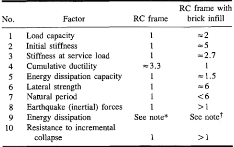
Table 1. Comparison of infilled frame behaviour with reinforced concrete frame behaviour.
-
RC frame with No. Factor RC frame brick infill
1 Load capacity 1 = 2 2 Initial stiffness 1 = 5
3 Stiffness at service load 1 ~ 2 . 7 4 Cumulative ductility ~ 3 . 3 1 5 Energy dissipation capacity 1 = 1.5
6 Lateral strength 1 = 6
7 Natural period 1 < 6
8 Earthquake (inertial) forces 1 > 1 9 Energy dissipation See note* See note? 10 Resistance to incremental
collapse 1 > 1
*Energy dissipation through large inelastic rotations at hinge regions. +Energy dissipation through hysteretic behaviour (friction across panel cracks).
infilled frame is compared with that of a bare RC frame in Table 1. This comparison, using performance factors, is based on the results from previous investigations, mainly on single-storey one-bay reinforced concrete infilled frames, which are discussed in the following section. It can be seen from Table 1 that the composite system, consisting of RC frames infilled with bricks, exhibits higher load capacity, stiffness, energy dissipation, and lateral strength.
Laboratory investigations
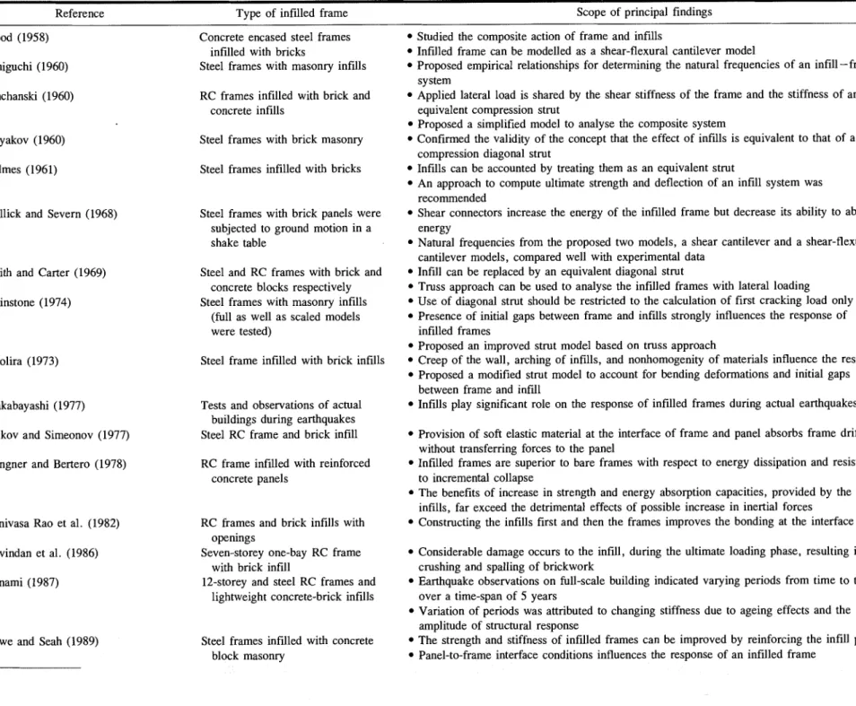
A list of reported laboratory studies is given in Table 2, which also contains the material type of the frame and the infill, as well as a summary of the scope and principal find- ings from each study. Tests were designed such that the influence of some of the parameters, such as the type of material in infill and frame, type of connection, and loading type, could be studied.
The review of the laboratory investigations (Kodur et al. 1994) on the behaviour of infilled frames revealed that the frame
-
infill interaction plays a significant role in determin- ing the dynamic response of the system. The extent of the interaction was found to vary from partial to full interaction in a number of these studies. Some contradictions on the effect of infill on the behaviour of infilled frames were revealed in these studies. A typical example of these contra- dictions can be seen from the conclusions reached by Klingner and Bertero (1978) and Govindan et al. (1986) in their studies. Klingner and Bertero, based on experimental results, predicted that the increase in strength and energy absorption would offset the detrimental effects of the possible increase in inertia forces, while Govindan et al. indicated that considerable damage would occur to the infill during the final stages of loading resulting in crushing of the brickwork. This raises doubts regarding the true influence of infills on the behaviour of infilled frames when subjected to seismic loads.Many of the laboratory investigations were specifically designed to study the beneficial effects of infills. In many cases the extent of the frame-infill interaction was almost complete by a result of the favourable laboratory conditions, such as minimum shrinkage due to ideal conditions for curing,
Table 2. Laboratory tests on infilled frames subjected to lateral loading.
Reference Type of infilled frame Scope of principal findings
Wood (1958)
Taniguchi (1960)
Sanchanski (1960)
Polyakov (1960)
Holmes (1961)
Mallick and Severn (1968)
Smith and Carter (1969)
Mainstone (1974)
Smolira (1973)
Wakabayashi (1977)
Velkov and Simeonov (1977)
Klingner and Bertero (1978)
Srinivasa Rao et al. (1982)
Govindan et al. (1986)
Minami (1987)
Dawe and Seah (1989)
Concrete encased steel frames infilled with bricks
Steel frames with masonry infills
RC frames infilled with brick and concrete infills
Steel frames with brick masonry
Steel frames infilled with bricks
Steel frames with brick panels were subjected to ground motion in a shake table
Steel and RC frames with brick and concrete blocks respectively Steel frames with masonry infills
(full as well as scaled models were tested)
Steel frame infilled with brick infills
Tests and observations of actual buildings during earthquakes Steel RC frame and brick infill
RC frame infilled with reinforced concrete panels
RC frames and brick infills with openings
Seven-storey one-bay RC frame with brick infill
12-storey and steel RC frames and lightweight concrete-brick infills
Steel frames infilled with concrete block masonry
Studied the composite action of frame and infills
Infilled frame can be modelled as a shear-flexural cantilever model
Proposed empirical relationships for determining the natural frequencies of an infill-frame system
Applied lateral load is shared by the shear stiffness of the frame and the stiffness of an equivalent compression strut
Proposed a simplified model to analyse the composite system
Confirmed the validity of the concept that the effect of infills is equivalent to that of a compression diagonal strut
Infills can be accounted by treating them as an equivalent strut
An approach to compute ultimate strength and deflection of an infill system was recommended
Shear connectors increase the energy of the infilled frame but decrease its ability to absorb energy
Natural frequencies from the proposed two models, a shear cantilever and a shear-flexural cantilever models, compared well with experimental data
Infill can be replaced by an equivalent diagonal strut
Truss approach can be used to analyse the infilled frames with lateral loading Use of diagonal strut should be restricted to the calculation of first cracking load only Presence of initial gaps between frame and infills strongly influences the response of infilled frames
Proposed an improved strut model based on truss approach
Creep of the wall, arching of infills, and nonhomogenity of materials influence the response Proposed a modified strut model to account for bending deformations and initial gaps between frame and infill
Infills play significant role on the response of infilled frames during actual earthquakes
Provision of soft elastic material at the interface of frame and panel absorbs frame drifting without transferring forces to the panel
Infilled frames are superior to bare frames with respect to energy dissipation and resistance to incremental collapse
The benefits of increase in strength and energy absorption capacities, provided by the infills, far exceed the detrimental effects of possible increase in inertial forces Constructing the infills first and then the frames improves the bonding at the interface
Considerable damage occurs to the infill, during the ultimate loading phase, resulting in crushing and spalling of brickwork
Earthquake observations on full-scale building indicated varying periods from time to time over a time-span of 5 years
Variation of periods was attributed to changing stiffness due to ageing effects and the amplitude of structural response
The strength and stiffness of infilled frames can be improved by reinforcing the infill panel Panel-to-frame interface conditions influences the response of an infilled frame
Kodur et al
point loading, low frame span to height ratios, and no open- ings. The same conditions cannot be expected in practice, where infilled frames will have characteristics such as greater shrinkage, varying distributed load throughout the height of the frame, higher frame span to height ratios, and door and window openings. This was recognized by some researchers (Minami 1987; Yamazaki et al. 1990) who resorted to obser- vations on full-scale buildings. Other researchers have com- mented that some of the limitations of the laboratory studies, such as using infilled frames with impractical characteristics, can be overcome using analytical models.
Analytical studies
The different models used for the analysis of infilled frames are shown in Table 3, together with the steps associated in the analysis. Of the different methods, the stress function method is the simplest, while the finite element method is the most complex and can also be used for nonlinear analysis. Results from the analysis, from any of the methods listed in Table 3, depend on the assumptions made and the idealiza- tion of the structure used in the analysis. In the plastic method of analysis, only the ultimate collapse load can be deter- mined, and very little information about the deflections, strains, and stresses can be obtained. A nonlinear analysis, which is capable of predicting realistic behaviour of an infilled frame, is recommended only for important engineering struc- tures, such as tall buildings located in high seismic areas, because of the complexity and effort involved in the analysis. From the review of the previous analytical investigations, it was found that while static loading on infilled frames has received considerable attention, comparatively few analytical studies have been reported with actual seismic loading (Kodur et al. 1994). This could be attributed to the complexity involved in the dynamic analysis. In the earlier investigations, infills were modelled as diagonal struts, while in recent years, the finite element method has been used to trace the response of the infilled frame subjected to varying lateral loads. The empirical relations proposed by researchers, based on analyt- ical studies, can be used in the preliminary design calcula- tions. Further, the review indicated that many codes of practice, which do not recognize the effect of infill panels, recommend the calculation of base shear as a function of the natural period of the structure computed by taking only the frame into consideration.
The New Zealand masonry code (Standards Association of New Zealand 1990) recognizes the effect of infills in that it specifically requires the interaction of all structural and nonstructural elements which, due to seismic displacements, might affect the response of the structure or the performance of nonstructural elements to be considered in the design. The design provisions in this code are largely governed by seismic load considerations and provide satisfactory structural per- formance during major earthquakes. The code requires special consideration of the infill to ensure diagonal bracing action when structural modifications result in openings. The provi- sions for structural design of masonry in Canada are governed by Canadian Standard CAN-S304-M84 (CSA 1990). The specified loads, load effects, and load combinations are com- puted according to the requirements of the National Building Code (NBC 1990), and the code specifies minimum rein- forcement to be provided in the masonry walls.
580 Can. J. Civ. Eng. Vol. 22, 1995
Table 3. Analytical methods for the analysis of infilled frames. Method (reference)
Stress function method (Polyakov 1960)
Equivalent diagonal strut method (Smith 1967; Sobaih and Abdin 1988)
Equivalent frame method (Liauw 1972; Liauw and Lee 1977)
Finite element method (Mallick and Severn 1968; Riddington and Smith 1977)
Plastic method of analysis (Liauw and Kwan 1984, 1985)
Salient features
-
The panel and frame elements of infill panel are assumed to resist a percentage of the total load The load carried by infill and frame is estimated through an iterative approach
The analysis can be carried out using hand calculations; however, the method is approximate The infill is idealized as diagonal struts, and the frame is modelled as beam or truss elements Frame analysis techniques are used for the elastic analysis
The idealization is based on the assumption that there is no bond between frame and infill Frame-infill composite system is replaced with an equivalent frame, and equivalent transformed properties are established
Elastic analysis is carried out using beam elements
Idealization is suitable for specifying varying properties or to account for openings
Infilled-frame system is idealized as panel elements, beam elements, and interface elements to simulate the structural interface
Interface conditions can be properly simulated by adjusting the properties of interface elements The analysis requires the use of a computer, but detailed results can be obtained
The frame-infill system is idealized as either integral, or semi-integral, or non-integral frame, depending on the interface conditions
Plastic collapse load corresponding to different possible mechanisms is determined
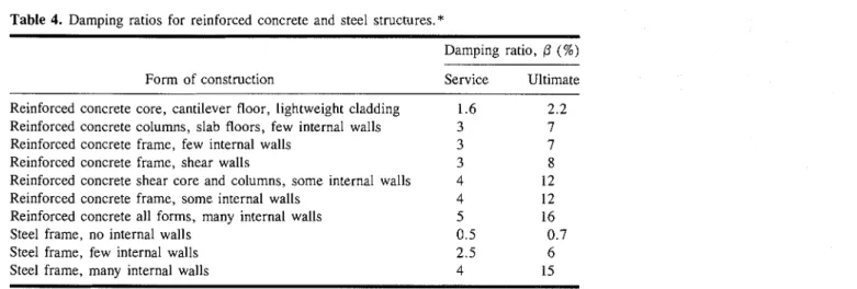
Table 4. Damping ratios for reinforced concrete and steel structures.*
Damping ratio, /3 (%)
Form of construction Service Ultimate
Reinforced concrete core, cantilever floor, lightweight cladding 1.6 2.2 Reinforced concrete columns, slab floors, few internal walls 3 7 Reinforced concrete frame, few internal walls
Reinforced concrete frame, shear walls
Reinforced concrete shear core and columns, some internal walls 4 12 Reinforced concrete frame, some internal walls
Reinforced concrete all forms, many internal walls Steel frame, no internal walls
Steel frame, few internal walls Steel frame, many internal walls
*Source: Cook 1985.
Very few guidelines for the practicing engineers, for the design and analysis of infilled frames, can be derived from the previous analytical studies. Recently, some researchers (Vintzeleou and Tassios 1989) have called for developing simplified analytical models which can be used by practicing engineers for the design and analysis of infilled frames. Efforts are being made for the development of simple guidelines that could be used by the practicing engineers in the design of reinforced masonry in all seismic zones (Noland 1990).
Simplified analysis technique
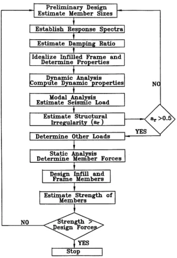
In the analysis technique proposed herein, the presence of infills is accounted for in all three stages of the analysis, namely in computing the seismic load, in determining the forces in the members, and in determining the strength of the different components of the composite system. The steps associated with the seismic design and analysis of infilled frames are illustrated in the flow chart shown in Fig. 1. Initially, the design and the seismic response spectra are established from codes. The infilled frame is idealized as
carried out to determine the dynamic properties. These proper- ties are used to compute the base shear through a modal analysis procedure. The vertical structural irregularities which arise from nonuniform distribution of infills are accounted for by the structural irregularity parameter, a,, which is estimated for the infilled frame; if a,
<
0.5, the vertical distribution of the infills is modified and the above steps are repeated.A static analysis of the infilled frame, with all loads, is ~erformed and the member forces in the infill and the frame members are estimated. The columns, beams, and infills are designed for these forces. The strengths of the members are estimated, under different failure modes. If these strengths exceed the design forces, the design is said to be safe. If the design forces exceed the strength, then the member sizes are modified, and the above procedure is repeated. The detailed procedure to be followed in each stage of the analysis is described in the following sections.
Seismic load
To accurately predict the seismic loads, the dynamic proper- described in design guidelines, and a dynamic analysis is ties of the structure must be known. The infilled frame is
Kodur et al.
Fig. 1. Steps associated with the seismic design of an infilled frame.
1 Estimate Member Sizes 1
I
I
I
Establish Response spectralt
I
I
I
Estimate Damping RatioI
1
I
I
I
Idealize Infilled Frame andDetermine Properties
I
Modal ApalJIsis Estimate Seisrmc Load
1
Stop1
idealized as recommended in design guidelines, and the equiva- lent properties of the infilled frame or the diagonal strut are established. A dynamic analysis is performed, and the natural period (T), natural frequency (a), and mode shapes
(4)
are determined. In the analysis, it is sufficient to consider only the first three modes, since higher-order modes do not sig- nificantly alter the response of the frame (Smith and Coull 1991) for buildings less than ten storeys high. The dynamic properties thus established are used to determine the base shear due to the seismic load through modal analysis.The earthquake response spectra, showing the accelera- tion (S,'), velocity (S:), and displacement (S,), corresponding to an earthquake is selected from design codes. The design value of the peak ground acceleration at the site of the build- ing location is obtained from codes (NBC 1990). The response of a structure depends on the damping present in the struc- ture, and the value of the structural damping ratio for the infilled frame under consideration is obtained from Table 4. The values of S,', S:, and S,, corresponding to a structural damping ratio and a natural period, are obtained from the selected response spectra in all three modes. The design values of S,, S,, and Sd, in all the modes, are computed by multiplying the respective values with peak ground acceleration.
In the modal analysis, to account for the effect of the infill, an equivalent frame is used to estimate the seismic
load. The properties of the equivalent frame are estimated and the maximum base shear is computed as described by Kodur et al. (1994). The maximum base shear thus obtained is distributed as lateral forces to different storeys, based on their masses. At each storey, the lateral forces are further distributed to different columns of the corresponding storey.
Static analysis
The second stage in the seismic design is to establish the response of the infilled-frame composite system under different loading combinations. The different loads to be considered in the analysis are computed as recommended in codes of practice. Torsional loads that might arise from a nonsym- metrical distribution of the infills are calculated. The total load acting on the infilled-frame system is established, with due consideration to any load factors and load combination factors, as given in codes of practice.
The infilled frame is idealized, and an elastic analysis is carried out. The member forces in the columns, beams, and infills and the resulting deflections are computed. These member forces are used as the design values, and the infills and frame members are designed as recommended in codes of practice.
Strength of frame and infills
Having determined the forces in the frame members, the next step is to check the adequacy of the infilled-frame system for the induced forces. The cracking and failure modes are to be considered in carrying out these checks for both concrete frames and infills, since increased cracking leads to crushing of these members. The design of the frame and infill is satis- factory when the computed strengths for anticipated modes of failure exceed the design forces in these members. In the strength calculation for the seismic loading, only the failure modes corresponding to the columns and infills are consid- ered in this section, because the beam stiffness has very little effect on the behaviour of infilled frame (Smith and Carter 1969). However, strength checks for beams, corresponding to usual failure modes, should be carried out during the course of the analysis.
The possible modes of frame failure that result from the presence of seismic loads are tension failure of the windward columns, or shear failure of the columns and beams (Smith and Carter 1969). If the frame strength is sufficient to with- stand collapse by one of these modes, the increasing load eventually produces failure of infills. In concrete infills, the usual failure modes are tension cracking along the compres- sive diagonal, followed by crushing near one of the loaded comers. In the case of a relatively stiff frame, crushing might occur in the interior region of the infill. For infills constructed with brick masonry, shear failure along the mortar joint to masonry panel should be considered. The strength of the columns and infills under different cracking and failure modes is computed, using empirical relationships developed by previous researchers (Govindan et al. 1986; Smith and Carter 1969), as described by Kodur et al. (1994).
Design guidelines
Implementation of the proposed analytical procedure in the design process requires detailed knowledge of some of the
Can. J. Civ. Eng. Vol. 22, 1995
Fig. 2. Idealization of an infilled frame: (a) diagonal strut;
(b) equivalent frame. (a)
b: Beam Element b: Beam Element t: Truss Element
factors that influence the behaviour of infilled frames. Some of the factors that are relevant to the seismic analysis of infilled frames are discussed in the following, with practical design recommendations.
Idealization of infilled frames
In the proposed approach, the infill is accounted for in the static and dynamic analysis by idealizing the infilled frame as either a frame-diagonal strut system or an equivalent frame system. In the frame-diagonal strut system, the infill is modelled as an equivalent diagonal compressive strut. While in the equivalent frame system, the action of the infill and that of the frame are combined to obtain an equivalent frame. The frame-diagonal strut idealization is suitable for frames with no shear connectors, while the equivalent frame ideali- zation can be used in cases where there are shear connectors or openings. The two idealizations for a typical infilled frame are shown in Fig. 2. When the frame-diagonal strut idealiza- tion is used, the columns and beams of the frame are modelled as beam elements, with three degrees of freedom at each node, namely rotation and two displacements, while the diagonal strut is modelled using truss elements. For the case of the equivalent frame idealization, beam elements are used. Shear deformations and axial deformations should be included for both idealizations, since these effects are predominant when the infilled frame is subjected to seismic or other lateral loads. When additional loads, induced by irregular geometry or torsional effects, are to be applied in between the storeys, the analysis can be facilitated by using more than one beam ele- ment for each column and beam. This approach is also useful when varying properties along the length of the frame mem- bers are specified or when deflections and rotations at points other than at beam-column joints are to be obtained.
Diagonal struts
When the infill is modelled as an equivalent diagonal strut, the contact length parameter (A) and width ( w ) are computed using the relationships proposed by Mainstone (1974):
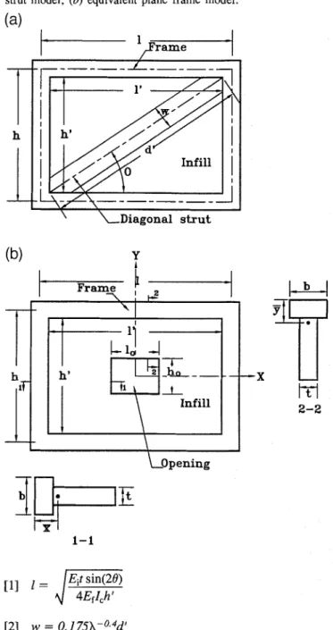
Fig. 3. Dimensions of an idealized infilled frame: (a) diagonal strut model; (b) equivalent plane frame model.
(a)
where Ei is the modulus of elasticity of the infill material, E f is the modulus of elasticity of the frame material, I, is the moment of inertia of column, and t is the thickness of infill. The variables h , h ' , d ' , and 0 are shown in Fig. 3a, which shows the analytical idealization of an infill panel as an equivalent strut. Knowing the values of X and w , the other design parameters required for the analysis, namely area of infill (Ai = wxt), length of contact
(M),
and panel ratio(l'lh') can be determined.
Equivalent frame
When an infilled frame is idealized as an equivalent frame, as shown in Fig. 3b, the effect of the infill is accounted for by modifying the properties of the frame. The properties of the equivalent frame are computed using the procedure
Kodur et al.
Fig. 4. Influence of decreased natural period of infilled frame on design spectrum.
recommended by Liauw (1972). It should be noted that the comer parts of the infill are used twice to calculate the moment of inertia of the beams and columns of the frame. This tends to increase the stiffness of the frame, which is to be expected, since the corners of the infill stiffen both the beams and columns.
Damping ratios
Damping plays a significant role in determining the behaviour of an infilled frame subjected to seismic loads. The amount of damping in a structure depends on the magnitude of the displacements and the stress levels. Cook (1985) has given typical values of damping ratios
(P)
for different types of concrete and steel frames, both at service and at ultimate conditions. These values are reproduced in Table 4. It can be seen from Table 4 that the damping ratio is higher for ulti- mate load levels, and that the presence of infill increases the damping, for both steel and reinforced concrete frames, at service and ultimate conditions. The ultimate damping ratio is to be used when the response of the structure is traced from precracking to collapse using a nonlinear analysis. For an elastic analysis, appropriate damping ratios corresponding to the service state should be used.Uncertainty in design
When infills are included in the analysis, the natural period of the structure decreases owing to increased stiffness. The effect of this decreased natural period on the base shear value depends on the characteristics of the expected ground motion. Therefore, the addition of infills might be favourable or unfavourable from the point of base shear, depending on the frequency content of the ground motion (Vintzeleou and Tassios 1989).
However, during the course of the design, only unfavour-
able effects of the infill on the natural period of the building are to be considered. This is because the effect of a first earthquake might cause some damage to the infill, resulting in a decrease in the stiffness of the frame. A decreased stiff- ness results in an increased period. Consequently, during a subsequent earthquake, the frame might attract higher forces.
A typical case of the above situation is illustrated in Fig. 4. The natural period of the frame, TBS, reduces to TI,, when the infills are accounted for, resulting in an increase in seismic acceleration from a1 to a; for the first (I) earthquake. How- ever, due to this earthquake, the infills are slightly damaged resulting in a decreased stiffness, thereby leading to a decrease in the period of TBS. When the second earthquake occurs near the site of this frame, the peak acceleration would be an instead of ah. So the design spectrum for this frame should be drawn by considering both cases as represented by the elastic design spectrum in Fig. 4.
Structural irregularities
Both horizontal and vertical structural irregularities arise if the infills are not uniformly distributed in plan and elevation. These irregularities influence the seismic behaviour consid- erably. Vertical irregularities arising from the nonuniform distribution of infills along the height of the building might cause considerable variation of the difference between the available and required shear resistances from floor to floor, leading to an increased ductility demand.
The ratio between the minimum
$
and the average value of i is called the regularity index, a,, where$
is computed as the ratio between the available shear resistance, VRj, and the required shear resistance, V*. For vertically regular buildings, a , is close to unity. If the value of a , is less than 0.8 for the jth storey, then additional design steps to account for reduced ductility are to be used (Vintzeleou and TassiosCan. J. Civ. Eng. Vol. 22, 1995 1989). Buildings with a,
<
0.5 should be modified so as toget a higher value of a,, since the actual seismic behaviour of highly irregular buildings is unpredictable, even when using elaborated mathematical models (Vintzeleou and Tassios 1989). It is recommended to design the structures with a minimum value of a, of 0.8.
The horizontal irregularity of the building arising from a nonuniform distribution of infill walls in-plan introduces additional torsional seismic effects. For computing horizontal irregularity, due to the nonsymmetrical distribution of infill walls in-plan, an equivalent stiffness should be used when determining the coordinates of the centre of stiffness. The distance between the centre of the masses and the centre of stiffness should be used to calculate the torsional effects on infilled frames.
Torsional effects
Torsional effects result from lateral forces applied at the centre of the floor mass, at an eccentricity from the centre of rigidity. Additional torsional effects may result during the dynamic response of the structure, if the assumed stiffness in the analysis differs from the actual stiffness. The torsional effect of an infilled frame, due to the shift of the centre of rigidity, is estimated to be similar to that for a bare frame (Paulay and Priestley 1992). The difference between the actual and assumed stiffnesses of the frame can be eliminated by using the equivalent stiffness of the infilled frame in the analysis.
Computational aids
Any frame analysis program, which has static and dynamic analyses options, can- be used for the design of infilled frames subjected to seismic loads. The frame analysis, both static and dynamic analyses, can be carried out using the frame analysis program; and the remaining steps associated with the proposed analytical procedure (Fig. 1) can be carried out on a spreadsheet. These steps include calculating the base shear using a modal analysis, computing the equivalent proper- ties, designing the infill-frame members, and determining the strength of the members. Shear deformations and axial deformations should be accounted for in the analysis. The use of a spreadsheet software for these calculations has the advantage of simplicity and ease in modifying the design for different cases.
Construction guidelines
Available ex~erimental observations indicate that it is mssible to achieve a nonseparating, tight interface condition by follow- ing certain steps during construction. The following guidelines can be implemented during the construction phase in order to get a good frame to infill monolithic action, thereby improv- ing the behaviour of the composite system (Thiruvengadam 1985; Velkov and Simeonov 1977).
1. Proper care should be taken to check the water absor- bent quality of bricks, and the bricks should be soaked well before placing them in position in order to reduce the shrinkage of masonry and the resulting interface gaps.
2. A rich mortar when applied at the frame to masonry interface, with an expansive-type cement, improves the bond- ing and minimizes the initial gaps.
3. Shear connectors should be provided in the form of
protruding steel reinforcement, taken from the column mem- bers and anchored in the courses of masonry. Vertical dowels from the supporting beam when connected to the infill also improve the composite action.
4. The bonding at the interface can be improved signifi- cantly by constructing the brick masonry first, and then casting the reinforced concreteTrame using masonry as part of form- work for concrete. The filler walls and the structural frame may be constructed in stages. This practice, though not prac- tical in North American construction, was found to be bene- ficial (Srinivasa Rao et al. 1982).
5. Hollow block masonry, when used for constructing masonry infill walls, can be used to obtain good connection, since the reinforcement taken from the frame members can be anchored inside the void of the blocks which can be subse- quently filled with plain concrete.
6. The doorway openings should be placed preferably at the centre of the panel in order to allow the diagonal strut action to be developed in the infilled frame. It should be noted that the infills with large openings do not behave as - -
solid panels and the compressive strut gction might not be obtained in such situations.
7. Shattering and spalling of masonry infills leading to explosive failure during an earthquake can be avoided by adding well-anchored light wire meshes on both faces of the infill walls.
8. The vertical load imposed to an infilled frame improves the confinement of the infill, which leads to increased strength and improvement in the overall behaviour of the inffilled frame. 9. If the infills are not connected to the frame, then soft elastic material can be used at the interfaces of the frame and the panel to absorb the frame drifting and to buffer the transfer of forces to the panel.
The infilled-frame system, damaged by the earthquake, can be repaired and strengthened in order to resist future seismic loadings. Zarnic et al. (1986) have given some prac- tical methods for the repair of such structures.
Numerical example
The proposed analytical procedure was applied to the seismic design and analysis infilled frames and results from a typical infilled frame example are discussed in the following. Detailed calculations are presented in Kodur et al. (1994).
The analysis was carried out for the infilled frames located in a three-storey three-bay reinforced concrete building. The building was assumed to be located in a seismic zone with peak ground acceleration of 0.4g, and the analysis was carried out for three cases. In the first case, Case A, the analysis was carried out by taking the contribution of the frame acting without infill, or the bare frame. The effect of infill through- out the frame is accounted for in Case B, which represents an infilled frame. In Case C, the openings present in the infill are considered.
The dynamic properties of the building, determined using the frame analysis computer program with the recommended idealization, are compared in Table 5. It can be seen from the table that the effect of the infill in Case B significantly reduces the natural period. The presence of openings in Case C results in a slightly higher natural period as compared to that in Case B. As expected, the natural period in all three cases
Kodur et al.
Fig. 5. Variation of base shear for three cases of frame idealization.
1
1
NBC
m
lnfill with opening
m
lnfilled frame0
I
Bare frameI
I 1 I t I 1 I I , I 0 10 20 30 40 50 60 7 0 80 90 id0Storey Shear Force (kN)
Table 5. Dynamic characteristics for the frame.
Property Bare frame (Case A) Infilled frame (Case B) Mode No. 1 2 3 1 2 3
Circular frequency (radls) 10.0 32.2 55.6 23.4 88.8 93.3
Natural frequency (Hz) 1.59 5.12 8.84 3.72 14.1 14.9 Period (s) 0.627 0.195 0.113 0.269 0.071 0.067 Mode shape 1 0.329 -1.127 2.446 0.234 1.147 0.286 2 0.743 -0.778 -2.365 0.636 -1.03 0.214 3 3 1 1 1 1 1
Infilled frame with opening (Case C)
1 2 3
20.2 78.6 92.8 3.21 12.5 14.8 0.311 0.08 0.07
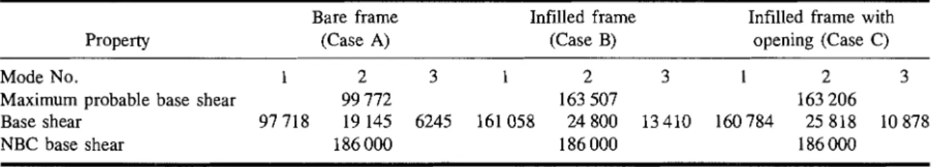
Table 6. Equivalent lateral forces and base shears for the frame. Bare frame
Property (Case A)
Infilled frame Infilled frame with (Case B) opening (Case C)
Mode No. 1 2 3 1 2 3 1 2 3
Maximum probable base shear 99 772 163 507 163 206
Base shear 97718 19145 6245 161058 24800 13410 160784 25818 10878
NBC base shear 186000 186 000 186 000
NOTE: All units are in Newtons.
decreases with higher-order modes. The mode shapes for cases A, B, and C varied widely from one case to the other, indicating that the variation in the behaviour of an infilled frame depends on the idealization used in the analysis.
The maximum probable base shear and the base shears in the three modes are presented in Table 6 for the three cases of analysis, together with the base shear as per National Building Code (1990). It can be seen from the table that the second and third modes have little influence on the maximum probable base shear values and confirms that higher-order modes need not be accounted for in seismic design and analysis. It can also be seen from the table that the maximum probable base shear is significantly higher in cases B and C,
indicating that the presence of infills attracts higher seismic loads. The higher shear can be attributed to the increased seismic acceleration, which results from the reduced natural period. The base shear calculated from NBC is higher than that obtained from modal analysis for all three cases. The NBC formula does not recognize the effect of infill panels and is very conservative when compared with the base shear of the bare frame. The effect of infills can be further seen in Fig. 5, which shows the variation of shear, resulting from seismic loads, in different storeys corresponding to three frame idealizations and that from NBC.
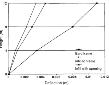
Figure 6 shows the plot of horizontal storey deflections for three cases of frame idealization. It can be seen from the
Can. J. Civ. Eng. Vol. 2 2 , 1995
Fig. 6 . Variation of storey deflections for three cases of frame
idealization.
Deflection (m)
figure that the top-storey deflection of the bare frame is nearly three times higher than that of the infilled frame. This increased deflection is inspite of the smaller magnitude of applied lateral forces at each storey. The deflections increase for Case C because of the reduction in stiffness from the presence of an opening.
Conclusions
The following conclusions may be drawn from the investiga- tion reported herein.
1. The behaviour of an infilled frame is dependent on the properties of frame and infill; hence, the response of such frames should be based on overall frame to infill composite action rather than on isolated bare frame behaviour.
2. The proposed analytical procedure accounts for the effect of infill in all stages of analysis: in computing the seismic loads, in predicting the response of the infilled frame, and in determining the strength.
3. The proposed analytical procedure can be implemented in the normal course of design and uses readily available computational tools.
4. The performance of an infilled frame can be improved by implementing recommended guidelines during the con- struction phase. These steps not only help in achieving the better composite behaviour, but also reduce the analytical complexity and uncertainty.
Acknowledgment
Funding for this study was provided by National Defence Canada.
References
Bertero, V.V., and Brokken, S. 1983. Infills in seismic resistant buildings. ASCE Journal of the Structural Division, 109(ST6): 1337 - 1361.
Carydis, P.G., Mouzakis, H.P., Taflambas, J.M., and Vougioukas, E.A. 1992. Response of infilled frames with brick walls to earthquake motions. Proceedings of the Tenth World Conference on Earthquake
Engineering, Ottawa, Ont., A.A. Balkema, Rotterdam, The Netherlands, pp. 2829 -2834.
Chavez, M. 1992. Seismic hazard and structural safety of Mexico City. Proceedings of the Tenth World
Conference on Earthquake Engineering, Ottawa, Ont., A.A. Balkema, Rotterdam, The Netherlands,
pp. 5797 -5802.
Cook, N.J. 1985. The designer's guide to wind loading of building structures. In Building research establishment. Part 1. Butterworths, London, United Kingdom. CSA. 1990. Masonry design for buildings. Canadian
Standards Association, Rexdale, Ont., Standard CAN3-S304-M84.
Dawe, J.L., and Seah, C.K. 1989. Behaviour of masonry infilled steel frames. Canadian Journal of Civil Engineering, 16(6): 865 - 876.
Dawe, J.L., Schriver, A.B., and Sofocleous, C. 1989. Masonry infilled steel frames subjected to dynamic load. Canadian Journal of Civil Engineering, 16(6): 877 - 885.
Ellis, B.R. 1980. An assessment of the accuracy of predicting fundamental natural frequencies of buildings and the implications concerning the dynamic analysis of structures. Proceedings, The Institution of Civil Engineers, 69(2): 763-776.
El-Quali, T., Houde, J., and Tinawi, R. 1991. Comportement d'un cadre rempli soumis h un chargement cyclique : modelisation pour une analyse dynamique non 1inCaire. Canadian Journal of Civil Engineering, 18(6): 1013 - 1023.
Govindan, P., Lakshmipathy, M., and Sanathkumar, A.R. 1986. Ductility of infilled frames. American Concrete Institute Journal, 83: 567 - 576.
Holmes, M. 1961. Steel frames with brickwork and concrete infilling. Proceedings, The Institution of Civil Engineers, 19: 473 -478.
Klingner, R.E., and Bertero, V.V. 1978. Earthquake resistance of infilled frames. ASCE Journal of the Structural Division, 104(ST6): 973-989.
Kodur, V.K.R., Erki, M. A., and Quenneville, J.H.P. 1994. Seismic behaviour and design of masonry-infilled frames. Royal Military College of Canada, Kingston, Ont., Civil Engineering Research Report CE 94-1. Liauw, T.C. 1972. An approximate method of analysis
for infilled frames with or without opening. Building Science, 7: 233-238.
Liauw, T.C., and Kwan, K.H. 1982. Nonlinear analysis of multistorey infilled frames. Proceedings, The Institution of Civil Engineers, Part 2, 73: 441 -454. Liauw, T.C., and Kwan, K.H. 1984. New developments
in research on infilled frames. Proceedings of the Eighth World Conference on Earthquake Engineering, Vol. IV, Prentice-Hall, Inc., Englewood Cliffs, N.J., pp. 623-630.
Liauw, T.C., and Kwan, K.H. 1985. Unified plastic analysis for infilled frames. ASCE Journal of the Structural Division, lll(ST7): 1427- 1448.
Liauw, T.C., and Lee, S.W. 1977. On the behaviour and the analysis of multi-storey infilled frames subject to lateral loading. Proceedings, The Institution of Civil Engineers, Part 2, 63: 641 -656.
Kodur et al
Mainstone, R.J. 1974. Supplementary note on the stiffness and strength of infilled frames. Building Research Station, Watford, United Kingdom, Current Paper C.P. 1314.
Mallick, D.V., and Severn, R.T. 1968. Dynamic characteristics of infilled frames. Proceedings, The Institution of Civil Engineers, 19: 261 -287. Minami, T. 1987. Stiffness deterioration measured on a
steel reinforced concrete building. Earthquake Engineering and Structural Dynamics, 15: 697 -709.
Mitchell, D. 1987. Structural damage due to the 1985 Mexico earthquake. Proceedings of the Fifth Canadian Conference on Earthquake Engineering, Ottawa, Ont., A. A. Balkema, Rotterdam, The Netherlands,
pp. 87-111.
Mitchell, D., Adams, J., Devall, R.H., Lo, R.C., and Weichert, D. 1986. Lessons from the 1985 Mexican earthquake. Canadian Journal of Civil Engineering, 13:
535 -557.
NBC. 1990. National building code of Canada. National Research Council of Canada, Ottawa, Ont.
Noland, L.J. 1990. 1990 status report: U.S. coordinated program for masonry building research. Proceedings of the Fifth North American Masonry Conference, Vol. 1, Urbana-Champaign, Ill., pp. 57-68. Paulay, T., and Priestley, M.J.N. 1992. Seismic design
of reinforced concrete and masonry buildings. John Wiley & Sons, Inc., New York, N.Y.
Pires, F., and Carvalho, E.C. 1992. The behaviour of infilled reinforced concrete frames under horizontal cyclic loading. Proceedings of the Tenth World
Conference on Earthquake Engineering, A.A. Balkema, Rotterdam, The Netherlands, pp. 3419 - 3422.
Polyakov, S.V. 1960. On the interaction between masonry filler walls and enclosing frame when loaded in the plane of the wall. Earthquake Engineering, Earthquake Engineering Research Institute, San Francisco, Calif., pp. 36-42.
Riddington, J.R., and Smith, B.S. 1977. Analysis of infilled frames subject to racking in design
recommendations. The Structural Engineer, 55(6):
263 -268.
Sanchanski, S. 1960. Analysis of the earthquake
resistance of framed buildings taking into consideration the carrying capacity of the filling masonry.
Proceedings of the Second World Conference on Earthquake Engineering, Vol. 2, Japan,
pp. 2127-2141.
Smith, B.S. 1967. Methods for predicting the lateral stiffness and strength of multistorey infilled frames. Building Science, 2: 247 -257.
Smith, B.S., and Carter, C. 1969. A method of analysis of infilled frames. Proceedings, The Institution of Civil Engineers, 44: 3 1 -48.
Smith, B.S., and Coull, A. 1991. Tall building structures -
analysis and design. John Wiley & Sons, Toronto, Ont. Smolira, M. 1973. Analysis of infilled shear walls.
Proceedings, The Institution of Civil Engineers, Part 2,
55: 895-912.
Sobaih, M., and Abdin, M.M. 1988. Seismic analysis of infilled reinforced concrete frames. Computers and Structures, 30(3): 457-464.
Sofocleous, C. 1988. Dynamic response of masonry infilled steel frames. M.Sc. thesis, Department of Civil Engineering, University of New Brunswick,
Fredericton, N.B.
Srinivasa Rao, P., Achyuta, H., Jagadish, R., and Devanarayanan, N. 1982. Influence of methods of construction on the behaviour of infilled frames. Proceedings of the Sixth International Brick-Masonry Conference, Rome, Italy, pp. 549-560.
Standards Association of New Zealand. 1990. Code of practice for the design of masonry structures. Part 1. Wellington, New Zealand, Standard NZS 4230. Stratta, J.L. 1987. Manual of seismic design.
Prentice-Hall, Inc., Englewood Cliffs, N. J. Taniguchi, M. 1960. Seismic wall effect in framed
structures. Proceedings of the Second World
Conference on Earthquake Engineering, Vol. 2, Japan, pp. 1013-1019.
Thiruvengadam, V. 1985. On the natural frequencies of infilled frames. Earthquake Engineering and Structural Dynamics, 13: 401 -419.
Velkov, M., and Simeonov, B. 1977. Earthquake resistant design of ten storeyed mixed steel and reinforced concrete structures with infill brick masonry. Proceedings of the Sixth World Conference on Earthquake Engineering, Vol. 2, New Delhi, India, pp. 1975-1979.
Villablanca, R., Klingner, R., Blondet, M., and
Mayes, L.R. 1990. Masonry structures in the Chilean earthquake of March 3, 1985: behavior and correlation with analysis. Proceedings of the Fifth North American Masonry Conference, Vol. 1, Urbana-Champaign, Ill., pp. 225-236.
Vintzeleou, E., and Tassios, T.P. 1989. Seismic behaviour and design of infilled RC frames. International Journal of Earthquake Engineering and Engineering Seismology, III(2) : 22 - 28.
Wakabayashi, M. 1977. Behaviour of systems. Proceedings of the Sixth World Conference on Earthquake Engineering, Vol. 1, New Delhi, India, pp. 65-76.
Wood, R.H. 1958. The stability of tall buildings.
Proceedings of the Institution of Civil Engineers, 11:
69 - 102.
Yamazaki, Y., Okamoto, S., Kaminosono, T., and Teshigawara, M. 1990. Seismic tests on a five storey full scale reinforced masonry building. Proceedings of the Fifth North American Masonry Conference, Vol. 1, Urbana-Champaign, Ill., pp. 69 - 80.
Zarnic, R., Tomazevic, M., and Tomaz, V. 1986. Experimental study of methods for repair and strengthening of masonry infilled reinforced concrete frames. Proceedings of the Eighth European
Conference on Earthquake Engineering, Vol. 5, Lisbon, Portugal, pp. 11.1141 -48.