Publisher’s version / Version de l'éditeur:
Vous avez des questions? Nous pouvons vous aider. Pour communiquer directement avec un auteur, consultez la première page de la revue dans laquelle son article a été publié afin de trouver ses coordonnées. Si vous n’arrivez pas à les repérer, communiquez avec nous à [email protected].
Questions? Contact the NRC Publications Archive team at
[email protected]. If you wish to email the authors directly, please see the first page of the publication for their contact information.
https://publications-cnrc.canada.ca/fra/droits
L’accès à ce site Web et l’utilisation de son contenu sont assujettis aux conditions présentées dans le site LISEZ CES CONDITIONS ATTENTIVEMENT AVANT D’UTILISER CE SITE WEB.
Paper (National Research Council of Canada. Institute for Research in
Construction); no. IRC-P-3487, 1993-12-01
READ THESE TERMS AND CONDITIONS CAREFULLY BEFORE USING THIS WEBSITE.
https://nrc-publications.canada.ca/eng/copyright
NRC Publications Archive Record / Notice des Archives des publications du CNRC :
https://nrc-publications.canada.ca/eng/view/object/?id=7cc614b7-a58f-4c98-a5f7-f62bb189d08d https://publications-cnrc.canada.ca/fra/voir/objet/?id=7cc614b7-a58f-4c98-a5f7-f62bb189d08d
NRC Publications Archive
Archives des publications du CNRC
For the publisher’s version, please access the DOI link below./ Pour consulter la version de l’éditeur, utilisez le lien DOI ci-dessous.
https://doi.org/10.4224/40000396
Access and use of this website and the material on it are subject to the Terms and Conditions set forth at
Guidelines for seismic evaluation of existing buildings
Allen, D. E.; Rainer, J. H.; Jablonski, A. M.
GUIDELINES FOR SEISMIC EVALUATION
OF EXISTING BUILDINGS
Preparedby:
Institute for Research in Construction National Research Council Canada
Funded by:
B.C. Buildings Corporation
B.C. Housing Management Commission Canada Mortgage and Housing Corporation Publics Works Canada
Societe Immobiliere du Quebec City of Vancouver
Institute for Research in Construction, NRC Canada
© National Research Council of Canada 1993 December 1993
ISBN 0-660-15382-3 NRCC 36941
NOTICE
These Guidelines have been prepared by the Institute for Research in Construction (IRC) of the National Research Council (NRC) Canada for the organizations listed above. With the agreement of these organizations these guidelines are made available to interested individuals or organizations for their information and review. These guidelines are not tobe intetpreted as replacing or superseding applicable building regulations. Neither the IRC nor the sponsoring organizations assume any liability for the use of this document.
ACKNOWLEDGMENT
These guidelines were developed from the preliminary version of ''NEHRP Handbook for Seismic Evaluation of Existing Buildings" issued by the u.s. Federal Emergency Management Agency (FEMA), Washington, D.C., in June 1992. The preliminary version of this document was prepared by the Applied Technology Council of Redwood City, California, and identified as "ATC-22" in its series of publications. These guidelines have been adapted to be compatible with Canadian practice and .the requirements of the 1990 National Building Code of Canada. A draft version was tried out on seven buildings across Canada. Feedback from trial applications plus a review of the "NEHRP Handbook for Seismic Evaluation of Existing BUildings" was used to revise those draft Guidelines. This project was made possible with joint funding from Public Works Canada, Canada Mortgage and Housing Corporation, B.C. Housing Management Corporation, Societe Immobiliere du Quebec, City of Vancouver, and the Institute for Research in Construction of the National Research Council Canada.
These guidelines were prepared by the following participants. D.E. Allen, principal investigator, IRC/NRC, Ottawa Contributors:
J.H. Rainer, IRC/NRC, Ottawa A.M. Jablonski, IRC/NRC, Ottawa
J. Blohm, Wayte Blohm & Associates, Victoria P. Byrne, University of British Columbia, Vancouver A. Caron, Polygec Groupe-Conseil, Levis
R. DeVall, Read Jones Christoffersen, Vancouver
F. Knoll, Nicolet Chartrand Knoll Limited, Montreal W. McKevitt, McKevitt Engineering, Vancouver
Robertson Kolbeins Teevan Gallaher Associates, Vancouver
The assistance of the U.s. Federal Emergency Management Agency (Mr. Ugo Morelli) and the Building Seismic Safety Council (Mr. James A. Smith) for providing ATC-22 on floppy disk as well as a draft and final version of the NEHRP Handbook is gratefully acknowledged, as well as the assistance of Mr. Mel Green of Melvyn Green and Associates, Manhattan Beach, California, and Mr. John Kariotis of Kariotis and Associates, South Pasadena, California, in providing information on the most recent criteria for seismic evaluation of unreinforced-rnasonry buildings.
BACKGROUND TO THIS DOCUMENT
These Guidelines are based on the NEHRP Handbook for Seismic Evaluation of Existing Buildings (FEMA 1992-1) produced by the
u.s.
Federal Emergency Management Agency and a preliminary version of the NEHRP Handbook called ATC-22 (1989). The following provides a background on the development of these Guidelines.
A draft version of these Guidelines was produced in June 1991 based on the ATC-22 (1989) document. The ATC-22 document was based on the methodology of ATC-14 (1987), the first set of practical guidelines on seismic evaluation of existing buildings in North America, in addition to studies on the application of ATC-14 to the eastern United States and to San Francisco, as well as trial applications to 100 buildings across the United States.
For the draft Guidelines, the following changes were made to the ATC-22 document:
(1) adaptation to the 1990 National Building Code of Canada (NBC) and the Canadian Standards Association (CSA) structural design standards.
(2) incorporation of the latest criteria for evaluation of unreinforced-masonry buildings with flexible floor/roof diaphragms (Uniform Code for Building Conservation 1991).
(3) imp r0 v e men t s con c ern i n g
foundations, seismic geological site hazards, moment frames, shear walls, and non-structural components.
(4) change in the title from "Handbook" to "Guidelines".
The draft version of these Guidelines was then tried out on seven buildings across Canada. The feedback from the trial applications plus a review of the 1992 NEHRP Handbook for Seismic Evaluation of Existing Buildings resulted in a number of changes to the draft Guidelines, including:
(5) a reduction factor of 0.6 from the NBC criteria (as compared to 0.75 used for the draft Guidelines) on the basis of risk and calibration studies described in Section 1.3.3 of these Guidelines.
(6) the use of a single comprehensive set of evaluation statements instead of 15 sets for different types of construction (to avoid repetition of evaluation statements and because many existing buildings contain two or more types of construction).
(7) a soil factor in the evaluation criteria for unreinforced-masonry bearing-wall buildings with flexible diaphragms contained in Appendix A (based on earthquake experience in zones of medium seismicity).
(8) adjustments to some of the NEHRP evaluation criteria to make them zone-dependent (many of the NEHRP criteria are conservative for regions of medium or low seismicity) as well as dependent on ground conditions.
It is hoped that experience with the application of these Guidelines will generate feedback which can serve to improve its usefulness in the future. To this end a User Comment form can be found at the end of the document to stimulate those who work with the Guidelines to report their experiences.
SUMMARY AND APPLICATION
These Guidelines are a technical manual that offers guidance to engineers in the seismic evaluation of existing buildings. These Guidelines are addressed to well-qualified structural engineers, but who are not necessarily experts in earthquake engineering.
The objective of the Guidelines is to identify typical structural deficiencies that have been observed in past earthquakes to lead to failure and falling of structural components and to partial or total collapse, with an attendant injury or loss of life.
The methodology and criteria of the Guidelines are based on life safety, not property damage, and therefore satisfy the basic life-safety objective of the National Building Code. They do not, however, comply with specific requirements of the National Building Code, which are appropriate for the design of new buildings.
The Guidelines present a set of questions that are designed to uncover weaknesses of the particular building being evaluated. The questions are in the form of Evaluation Statements that relate to various vulnerability areas in the structural system that require specific consideration. The Evaluation Statements are written so that a positive or 'true' response to a statement implies that the building is adequate in that area. If a building passes all applicable statements with 'true' responses, it can be passed without further evaluation, i.e., it is deemed not to be a life-safety hazard. For statements that are 'false,' additional evaluation is required. A 'false' statement does not necessarily imply that a complete structural evaluation is necessary, or that the building is automatically deficient; it simply flags an area of concern for the evaluating engineer and implies that a life-safety hazard may exist. Ifany such potential life-safety hazards are identified, an appropriate detailed analysis is recommended, with acceptance criteria suggested for each element of concern. Through this procedure, not
only are weak links in the structural system identified, but the presence of the life-safety hazard is also assessed.
These Guidelines provide a methodology that can be applied nation-wide to all existing buildings tha t are suspected of posing a potentially serious risk of loss of life and injury in case of a damaging earthquake. This procedure covers both structural and non-structural elements and requires the review of construction documents, the general condition of the building, and calculations. The Guidelines include checklists, diagrams, and sketches that help to guide the user.
These Guidelines are organized to be compatible with the NEHRP Handbook of Techniques for Seismically Rehabilitating Existing Buildings (FEMA, 1992-2). The NEHRP document
identifies and describes seismic rehabilitation techniques for a broad spectrum of building types and building components, including both structural and non-structural elements. To aid the reader in the process of moving from evaluation to rehabilitation, the Guidelines and the NEHRP document on upgrading techniques are both organized to address building systems and components. Building components are organized into the following subsystems: vertical elements resisting horizontal loads (i.e., moment-resisting frames, shear walls, and braced frames); horizontal elements resisting lateral loads (i.e., diaphragms); foundations; connections between subsystems; and non-structural building components. The NEHRP document has, however, not been adapted to be compatible with Canadian practice.
The Guidelines provide the tools to identify seismically hazardous buildings. It is not a directive or a requirement, but rather a practical technical approach that can be used to identify seismic deficiencies in existing buildings.
TABLE OF CONTENTS
ACKNOWLEDGMENT
BACKGROUND TO THIS DOCUMENT SUMMARY AND APPLICATION NOTATIONS
GLOSSARY
1. INTRODUCTION
1.1 Purpose of the Guidelines 1.2 Post-Disaster Buildings 1.3 Basis of the Guidelines
1.3.1 Scope and Limitations 1.3.2 Criteria
1.3.3 Force Level for Analysis 1.4 The Guidelines Methodology 1.5 Contents of the Guidelines 2. THE EVALUATION PROCEDURE
2.1 Site Visit and Data Collection
2.2 Determination of Lateral-Force-Resisting System and Initial Review of Evaluation Statements
2.3 Follow-Up Field Work 2.4 Analysis of the Building 2.5 Final Evaluation
2.5.1 Review the Statements and Responses
2.5.2 Assemble and Review the Results of the Seismic Evaluation 2.5.3 Develop a List of Deficiencies
2.5.4 Final Evaluation 2.6 The Final Report
3. ANALYSIS OF THE BUILDING 3.1 Scope of Analysis
3.2 Load Effects (Demand)
3.3 Seismic Analysis of the Building Structure 3.3.1 Base Shear
3.3.2 Quick Checks for Strength and Stiffness
3.3.3 Determination of Seismic Effects in the Building Structure 3.3.4 Dynamic Analysis
3.4 Seismic Forces on Parts and Portions of the Building 3.5 Element Capacities 3.6 Acceptance Criteria ii iii iv ix xi 1 1 1 1 2 2 2 3 3· 5 5 5 7 7 7 7 7 8 8 8 15 15 16 16 16 17 19 21 23 23 24
4. COMMENTARY AND PROCEDURES FOR BUILDING SYSTEMS 4.1 Load Path
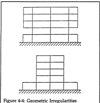
4.2 Redundancy 4.3 Configuration 4.4 Adjacent Buildings
4.5 Evaluation of Materials and Conditions
5. COMMENTARY AND PROCEDURES FOR MOMENT RESISTING SYSTEMS 5.1 Frames with Infill Walls
5.2 Steel Moment Frames 5.3 Concrete Moment Frames
5.4 Precast Concrete Moment Frames
5.5 Frames Not Part of the Lateral-Foree-Resisting System 6. COMMENTARY AND PROCEDURES FOR SHEAR WALLS
6.1 Concrete Shear Walls
6.2 Precast Concrete Shear Walls 6.3 Reinforced-Masonry Shear Walls
6.4 Unreinforced-Masonry Load-Bearing Walls 6.5 Unreinforced-Masonry Infill Walls in Frames 6.6 Walls in Wood-Frame Buildings
7. COMMENTARY AND PROCEDURES FOR BRACED FRAMES 7.1 Braced Frames
7.2 Concentric Braced Frames 7.3 Eccentric Braced Frames
8. COMMENTARY AND PROCEDURES FOR DIAPHRAGMS 8.1 Diaphragms - General
8.2 Wood Diaphragms 8.3 Metal Deck Diaphragms 8.4 Concrete Diaphragms
8.5 Precast Concrete Diaphragms 8.6 Horizontal Bracing
8.7 Other Systems
9. COMMENTARY AND PROCEDURES FOR CONNECTIONS 9.1 Anchorage for Normal Forces
9.2 Shear Transfer
9.3 Vertical Components to Foundations 9.4 Interconnection of Elements 9.5 Panel Connections 28 28 28 29 34 35 39 40 41 43 48 48 50 50 54 55 55 56 57 59 59 59 61 63 63 68 69 70 70 71 71 72 72 74 74 75 76
10. COMMENTARY FOR FOUNDATIONS AND SEISMIC GEOLOGIC SITE HAZARDS 10.1 Foundation Assessment Procedure
10.2 Subsurface Profile and Foundation Factor 10.3 Structural Aspects of Foundations
10.4 Soil Failure Due to Seismic Loading 10.5 Soil Strength Loss
10.6 Seismic Geologic Site Hazards
11. EVALUATION OF ELEMENTS THAT ARE NOT PART OF THE LATERAL-FORCE-RESISTING SYSTEM
11.1 Walls: Structural and Non-structural 11.2 Unintended Structural Effects 11.3 Life-Safety Concerns
11.4 Non-structural Elements 11.5 Performance Characteristics
11.5.1 Parapets, Cornices, Ornamentation, Chimneys, and Appendages 11.5.2 Exterior Cladding, Glazing, or Veneers
11.5.3 Means of Egress 11.5.4 Partitions 11.5.5 Ceiling Systems 11.5.6 Light Fixtures
11.5.7 Building Contents and Furnishings 11.5.8 Elevators
11.5.9 Mechanical/Electrical Equipment 11.5.10 Hazardous Materials
11.6 Other Issues
11.6.1 Cladding, Glazing, and Veneer 11.6.2 Partitions 11.6.3 Ceilings 11.6.4 Light Fixtures 11.6.5 Mechanical Equipment 11.6.6 Piping 11.6.7 Ducts 11.6.8 Electrical EqUipment 11.6.9 Elevator Equipment
11.6.10 Building Contents and Furnishings
77 77 77 77 78 78 80 84 84 84 85 85 85 86 86 86 86 86 86 87 87 87 88 88 88 89 89 89 89 89 89 89 90 90 REFERENCES 91
APPENDIX A: EVALUATION OF UNREINFORCED-MASONRY BEARING-WALL BUILDINGS 93 Al Scope A.2 Notations A3 Elements to be Evaluated A4 Analysis Procedure A.5 Masonry 93 93 94 94 95
A,6 Stability of Masonry Walls A,7 Masonry Wall Anchorage A,8 Masonry Wall Shear Force A,9 Masonry Wall Shear Resistance A,10 Wood Diaphragms
A,11 Crosswalls
A,12 Buildings with Open Fronts A,13 Truss and Beam Support A,14 Parapets
APPENDIX B: EXAMPLES OF EVALUATIONS B.l Steel Moment Frame Building
B.2 Steel Moment Frame and Braced Frame Building B.3 Steel Frame with Infill Walls of URM
B.4 Concrete Moment Frame Building B.5 Concrete Shear Wall Building B.6 Unreinforced-Masonry Building APPENDIX C: EVALUATION STATEMENTS
Evaluation Statements for The Basic Building System
Evaluation Statements for Vertical Systems Resisting Lateral Forces Evaluation Statements for Diaphragms (Horizontal Bracing Systems) Evaluation Statements for Structural Connections
Evaluation Statements for Foundations and Geologic Site Hazards Evaluation Statements for Non-structural Elements
APPENDIX D: DATA SUMMARY SHEET
97 97 98 98 99 100 100 101 101 109 110 114 117 122 124 126 131 132 134 141 143 145 146 150
s = S = Sp = t = T = Ta = U = v = Abr = Ac =
Aw
= C = Cp = D = Ds = DR = d =NOTATIONS
1.5 times the average area of a diagonal brace,mm2
Summation of the cross-sectional area of all columns in the storey under consideration
Summation of the horizontal cross-sectional area of all shear walls in the direction of loading with height-to-length ratios less than2.The wall area should be reduced by the area of any openings. Capacity
Response factor from Table3-5
Effect of dead load, Equations 3-1 to3-3
Overall length of the building or of shear/braced walls at the base, m Interstorey displacement divided by interstorey height (drift ratio)
Distance from compression surface to centroid of tension reinforcement in a reinforced concrete section,mm.
db = Diameter of reinforcing bar, mm.
E = Modulus of elasticity, MPa; effect of combined loads (total demand), Equations3-1 to3-3
F = Foundation factor
Fbr = Average axial force in diagonal bracing Ft = Shear force applied at the top of the building Fx = Shear force applied at level x,kN
h = Storey height, mm
セ = Height above the base to the highest level of the building, m
セ = Height of a wall or pier
hx
= Height above the base of the building to level xhit = Height-to-thickness ratio ofURMwall between wall anchorage levels and/or slab-on-grade
I = Moment of inertia, mm4;importance factor for base shear, Equation3-4
j = Number of storey levels under consideration
K = Effective length factor for buckling kb = IlL for the beam
kc = IlL for the column L = Span; effect of live load
セイ = Average length of the braces, m
lw
= Length of a wall or pierN = Total number of storeys above ground level
Nbr = Number of braces in tension for the direction of loading
nc = Total number of columns
nf = Total number of frames in the direction of loading
Q = Effect of seismic forces, Equations3-1 to3-3
R = Force modification factor from Table3-1
Average span length of braced spans, m Seismic response factor, Figure 3-1
Coefficient given in Table3-4
Wall thickness
Fundamental period of the building
Approximate fundamental period of the building, Equation3-5.
Calibration factor to determine base shear, Equation3-4 Peak horizontal ground velocity, Figure2-2
v·Fセ 0.4, a seismic input factor for criteria contained in Evaluation Statements. =Average shearing stress by Quick Check procedure, Equations 3-9and 3-10.
Base shear, Equation 3-4 Shear in the column, kN
V·
=
セ
=
=
セ
=
=
)w
x=
Za=
Zv =
y=
Storey shear at the level under consideration determined from Equation 3-7 Total lateral seismic force on part on portion of building.
Total dead load and applicable portions of certain other loads Weight of the element or component
Total seismic dead load of all storeys above level j Building weight at level x
Acceleration-related seismic zone Velocity-related seismic zone
GLOSSARY
Appendage: An architectural component, such as a canopy, marquee, ornamental balcony, or statuary. Base: The level at which the horizontal seismic ground motions are considered to be imparted to the building.
Base Shear: Total calculated lateral force or shear at the base.
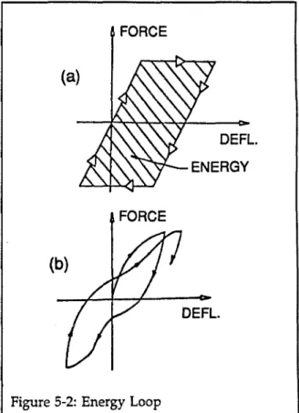
Brittle Systems: Systems that do not have a definite yield phase and that have a significant strength degradation immediately after the displacement associated with peak strength.
Chord: Edge of a diaphragm that acts in tension or compression (see Figure 8-1). Collar Joint: The vertical space between adjacent wythes, which may contain mortar. Collector: A member that transfers diaphragm shear into a shear wall (see Figure 8-4). Cripple Wall: Short stud wall between first floor and foundation wall.
Cross Wall: A wall that meets the requirements of SectionA.ll of AppendiX A.
Diaphragm: A horizontal, or nearly horizontal, system designed to transmit seismic forces to the vertical elements of the lateral-foree-resisting system.
Diaphragm Edge: The intersection of the horizontal diaphragm and shear wall. Drift Ratio: Interstorey lateral displacement divided by interstorey height.
Ductile Systems: Systems that have a definite yield phase. The post-yield load-displacement relationship is stable, but when displaced with multiple cycles, a system may have a strength less than the strength under monotonic loading.
Flexible Diaphragm: A diaphragm of wood construction or other construction of similar flexibility. Frame, Braced: An essentially vertical truss, or its equivalent, of the concentric or eccentric type that is provided to resist lateral forces.
Frame, Space: A three-dimensional structural system composed of interconnected members, other than bearing walls, that are capable of supporting vertical loads and that may also provide resistance to lateral forces.
Normal Wall: A wall perpendicular to the direction of seismic forces.
Open Front: An exterior building wall plane on one side only without vertical elements of the lateral-force-resisting system in one or more storeys.
Redundancy: The presence of multiple alternate load paths so that, if one or several elements have substantial strength and stiffness loss, continuing lateral displacement will be resisted by the other elements of the system.
Semi-Ductile Elements: Elements that yield and maintain only part of their yield strength while absorbing energy during repeated excursions into the inelastic range.
Storey Drift Ratio: The ratio of the maximum lateral displacement of a floor with respect to the floor below divided by the storey height.
Subsystems: A set of building elements that makes up a major portion of the lateral-foree-resisting system, such as diaphragms, moment frames, and shear walls.
Moment-Resisting Frame: A structural system with an essentially complete space frame providing support for vertical loads with moment resisting frames providing support for lateral loads.
Unblocked Diaphragm: A diaphragm made of panels having edges unsupported by wood joists or blocking.
Unreinforced-Masonry (URM) Wall: A masonry wall in which the area of reinforcing steel is less than 25% of the minimum steel ratios required by CSA Standard for reinforced masonry.
Unreinforced-Masonry Bearing Wall: A URM wall which provides the vertical support for a floor or roof for which the total superimposed load exceeds 1.5 kN/m of wall.
Veneer: Facing or ornamentation, not used to develop resistance to lateral forces, composed of brick, concrete, stone, tile, or similar materials that are connected to a backup structure either by anchorage or adhesion.
Vertical Elements: Subsystems in a vertical plane including shear walls, braced frames, and moment resisting frames.
Wall, Bearing: An interior or exterior wall providing support for vertical loads.
Wall, Nonbearing: An interior or exterior wall that does not provide support for vertical loads other than its own weight.
Wall, Shear: A wall, bearing or nonbearing, capable of resisting seismic forces acting in the plane of the wall.
1
INTRODUCTION
1.1 PURPOSE OF THE GUIDELINES These Guidelines are a technical manual that offers guidance for engineers in evaluating existing buildings to determine potential earthquake hazards and identify buildings or building components that present unacceptable risk to human lives. A building does not meet the life-safety objective of these Guidelines if in an earthquake one or more of the following events occurs:
• The entire building collapses. • Portions of the building collapse. • Components of the building fail and fall. • Exit and entry routes are blocked, preventing the evacuation and rescue of the occupants.
The identification of life-safety hazards in an existing building consists of determining whether any of these events could potentially happen during an earthquake that could be expected to occur. Hence, a major portion of the Guidelines is dedicated to directing the evaluating engineer on how to determine if there are any weak links in the structure that could precipitate structural or component failure.
To aid the reader in the process of moving from evaluation to rehabilitation, the Guidelines have been organized to be compatible with the
NEHRP Handbook of Techniques for Seismically Rehabilitating Existing Buildings (1992). Both
documents are organized to address structural systems and building components. Building components are organized into the following subsystems: vertical elements resisting horizontal loads (i.e., moment-resisting frames, shear walls, and braced frames); horizontal elements resisting
lateral loads (Le., diaphragms); foundations; connections between subsystems; and non-structural building components.
The information contained in both these documents is based primarily on experience gained in evaluating and upgrading buildings in areas of high seismicity. The evaluation statements and criteria in these Guidelines, while conservatively applicable to all seismic areas, should be tempered with engineering judgment when applied to low seismic areas. For buildings in acceleration- or velocity-related zones 0, 1, or 2 and founded on rock or firm soil, earth-quake experience shows that life-threatening damage to the building structure is very unlikely. Life-threatening damage to non-structural components, such as unsupported slender masonry parapets over entrances, is more likely. The risk of life-threatening damage increases not only with seismic zone but, equally important, with soil conditions. Most life-threatening building damage in past earthquakes in Canada has been to non-structural building components and most ofithas occurred on soft ground.
1.2 POST-DISASTER BUILDINGS
Post-disaster buildings generally must remain operational after an earthquake disaster. Although the procedures in these Guidelines can be used to evaluate the life-safety capability of post-disaster buildings, they will not necessarily assure continued post-earthquake performance.
1.3 BASIS OF THE GUIDELINES
The basis of the Guidelines is introduced here under four major aspects of the evaluation problem: scope, criteria, force level, and capacity versus demand. Other standards for evaluation are also discussed.
1.3.1 Scope and Limitations
The Guidelines deal with life-safety objectives; they do not address other objectives such as damageability (some guidance is given on p. 21 under 'Deformation and Drift') or building performance under special conditions. The buildings treated in the Guidelines are ordinary buildings with ordinary occupancies, not unusual or special structures, or structures devoted to industrial processes.
The deficiencies identified in the evaluation can be addressed under the guidance of the
NEHRP Handbook of Techniques for Seismic Rehabi-litation of Existing Buildings (FEMA, 1992-2). In
selecting rehabilitation schemes, however, an understanding of the overall deficiencies of the building is required, since the overall deficiencies may be due to a combination of component deficiencies, inherent adverse design and construction features, or a weak link.
It is recommended that the analysis called for in the Guidelines be carried out by appropriate simple procedures in order that truly hazardous buildings may be quickly identified. With this approach, it is anticipated that many existing buildings will not pass the tests given in the Guidelines. Failure to pass the tests does not automatically indicate a hazardous building. For marginal or questionable buildings, a more detailed investigation may be justified. Such an investigation would be most effectiveifdone as part of a building renovation program.
These Guidelines do not prevent an engineer from making a properly substantiated evaluation using other procedures.
1.3.2 Criteria
The criteria followed by the Guidelines are made compatible with the 1990 NBC seismic provisions. The development of seismic codes has always sought life-safety.Itis the consensus of the committee which developed the 1990 NBC seismic provisions that the specified ground motion is appropriate for design and that a building properly designed to both the specified base shear and the specified detail requirements
will have an acceptable level of life-safety. The criteria of the 1990 NBC provisions, written for the design of new buildings, are modified in these Guidelines for the purpose of evaluating existing buildings. It should be noted that the NBC seismic provisions are subject to ongoing revision as more is learned about ground motion and building response.
Nothing in these Guidelines should be inter-preted to mean that existing buildings must meet provisions more stringent than the NBC provi-sions for new buildings.
1.3.3 Force Level for Analysis
For investigation of existing buildings, some building codes, such as those for the City of Vancouver, specify a force level lower than that prescribed by the criteria for new buildings. This concept is generally acceptable because it is believed that a building should be substantially below the current standard before triggering the requirement for a costly seismic upgrade and because a higher level of earthquake damage is acceptable in an existing building. This accep-tance is based on an appraisal of the cost-benefits of the reduction of damage level due to seismic upgrading and on a rationalization that life-safety threats will be substantially reduced even if the possible earthquake damage level may be higher than that anticipated for new buildings.
The Guidelines adopt a reduction factor of 0.60 applied to the NBC seismic loading criteria, which corresponds to a V-factor of 0.36, as a minimum for triggering seismic upgrading for any deficiency. This reduction was chosen on the basis of the following considerations:
(1) The NEHRP criteria are based on a reduction factor of 0.67 for most buildings, 0.85 for stiff low-rise buildings. This reduction is justified in the NEHRP handbook as the removal of a hidden safety factor contained in the dynamic response factor (5-factor in the NBC) associated with the use of a response spectrum in the NEHRP model code corresponding to the mean-plus-one standard deviation rather than
the mean. Further background to this is given in ATC-14.
(2) A risk study (Allen, 1991) on minimum load factors for structural evaluation of existing buildings based on the life-safety goal of the NBC recommends that the NBC-specified earth-quake load can be reduced as a function of the consequences of the potential failure. The conse-quences are assessed on the basis of redundancy and the likelihood and number of people at risk (life-risk category). Assuming a medium' redundancy as recommended by these Guide-lines and a 'normal' life-risk category, the risk study (Allen, 1991) determines a reduction factor close to 0.6. The evaluator may wish to consider adjusting the factor 0.6 up or down, according to redundancy and life-risk category for each potential failure. Further guidance is given by Allen (1991).
(3) The resulting triggering criteria in the Guidelines were compared to those contained in the NEHRP handbook for the same seismicity (same ground velocity or acceleration), taking into account all factors entering into the determination onactored base shear. With a V-factor of 0.36, the Guidelines criteria range from a minimum of 0.9 to a maximum of 2.0 times the NEHRP handbook criteria. Thus the Guidelines criteria remain conservative in comparison with the NEHRP handbook criteria.
The Guideline force levels, with V
=
0.36, should be considered suitable as a triggering criterion for seismic upgrading for any identified deficiency. They should not be considered suitable for the design of the upgrading. For design of upgrading, the V-factor should be increased based on considerations of future building use, control of seismic damage (to the building and contents), and the differential in upgrading costs with force level.1.4 THE GUIDELINES METHODOLOGY
The methodology of the Guidelines is centred on a set of questions that is designed to
uncover the flaws and weaknesses of a building. The questions are in the form of positive Evaluation Statements that describe characte-ristics of the building type that are essential in avoiding the failures that have been observed in past earthquakes. The evaluating engineer addresses each statement and determines whether it is true or false. 'True' statements identify conditions that are acceptable. 'False' statements identify issues or concerns that need further investigation. The Guidelines specify a procedure for dealing with false statements.
The evaluation procedure consists of two phases. The first phase consists of an initial quick evaluation of the building involving an initial survey of a building and its drawings followed by a review of the Evaluation State-ments applicable to the building. This review includes Quick Check calculations triggered by Evaluation Statements for lateral resistance and displacement of the structure subjected to seismic forces. The result of the first phase is a list of potential deficiencies that either do not satisfy the Quick Checks or that cannot be answered without further investigation. The second phase of the evaluation procedure is focused on site investigations and detailed structural analyses to see whether or not the 'false' statements point to real deficiencies. One advantage of this approach is that it is often clear after the first phase as to whether the building is safe or whether it requires upgrading for deficiencies clearly identified, and therefore a detailed investigation may not be required. Another is that the second phase of the evaluation is focused on only potential deficiencies in the grey area between 'true' and 'false'.
1.5 CONTENTS OF THE GUIDELINES
The three major elements of the Guidelines are (1) the evaluation procedure, including Evaluation Statements, (2) structural analysis of the building, including the Quick Checks, and (3) the Commentary and Procedures to be used when the Statements are addressed.
Evaluation Procedure. Chapter2 provides a guide to the evaluation procedure, from the first look at the building to the final judgment of the capacity of the building to resist damage from earthquake ground motions.
Analysis of the Building. Chapter 3 and, for unreinforced,load-bearing masonry, Appendix A contain the methods of analysis and acceptance criteria for seismic evaluation.
Commentary and Procedures. Chapters 4
through 11 and Appendix A provide commentary on building systems and procedures for dealing with Evaluation Statements that are found to be false. The commentary includes definitions of the deficiencies that are addressed in NEHRP Handbook of Techniques for Seismic Rehabilitation of Existing Buildings(FEMA, 1992-2).
Chapters4 through11 cover:
1. Building systems (Chapter4)
2. Building subsystems
a. Vertical components of the lateral-force-resisting system (moment frames in Chapter5,shear walls in Chapter6,and braced frames in Chapter7)
b. Horizontal diaphragms (Chapter 8) c. Connections among the components (Chapter9)
d. Foundations and geological site hazards (Chapter 10)
3. Non-structural elements (Chapter11) Appendices. Appendices include the evaluation procedure for unreinforced, load-bearing masonry (Appendix A), examples for the application of the Guidelines (Appendix B), the set of Evaluation Statements to be used by the engineer (Appendix C), and the Data Summary Sheet (Appendix D).
2
THE EVALUATION PROCEDURE
The evaluation procedure includes the following steps:
1. Visit the site and collect data. 2. Determine the lateral-foree-resisting
system and make the initial review of the Evaluation Statements using, where required, the Quick Check procedures. 3. Perform follow-up field work.
4. Perform the analysis required for the 'false' Evaluation Statements.
5. Make the final evaluation. 6. Write the report.
2.1 SITE VISIT ANDDATA COLLECTION The evaluating engineer should be present on the first visit to the building during the planning of the proposal for the evaluation project, take photographs, and make the initial evaluation of the building. The engineer then should:
1. Look for an existing geotechnical report on site soil conditions.
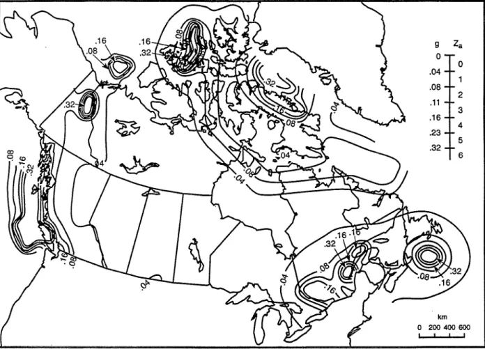
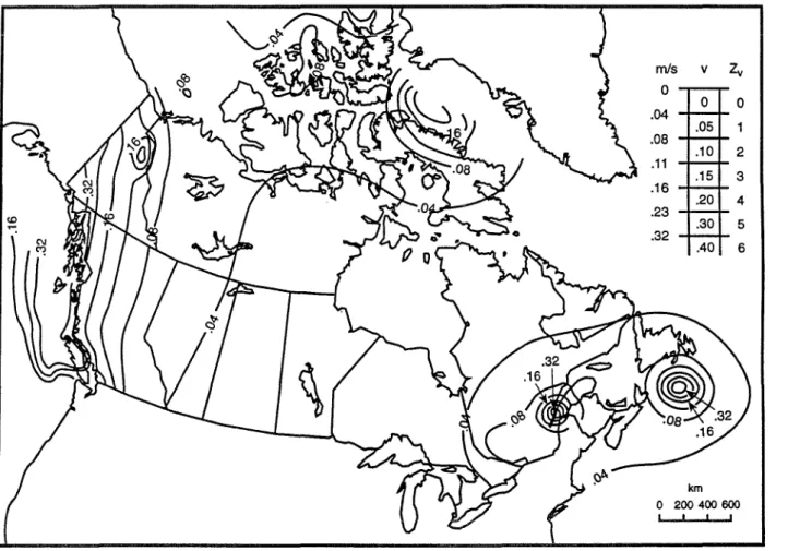
2. Establish the site and soil parameters: a. the values of the acceleration zone (Za) and the velocity zone (Zv) from the Supplement to the 1990 NBC (See Figures 2-1 and 2-2)
b. the appropriate foundation factor (F) from Table 3-2 based on the soil profile derived from the geotechnical report or other information.
3. Assemble building design data:
a. Obtain original contract drawings, specifications, and calculations. (Note: When reviewing and making use of existing analyses and member checks, the engineer should be careful about the basis of the work. The 1990 NBC seismic provisions are on alimitstate basis and use appropriate R-factors. Previous codes may have a different basis, such as working stress design.) b. Obtain similar information for
previous renovation work.
4. Look for performance data: previous earthquake evaluations of the building, and other performance data or damage investigations.
5. Make an initial site survey of the building to verify building design data and, where possible, the conditions of building components.
6. Make a summary of the data: record the data on the form in Appendix D. There are several substantial difficulties in evaluating buildings. One is the matter of uncovering the structure. In many buildings the structure is concealed by architectural finishes. The engineer will have to get into attics, crawl spaces, and plenums. Lack of plans and calcu-lations may also be a problem. This is particu-larly frustrating in concrete work.
2.2 DETERMINATION OF LATERAL-FoRCE-RESISTING SYSTEM AND INITIALREvIEw OF
EVALUATION STATEMENTS
Having seen the building and assembled all available plans and other data, the engineer should determine the lateral-foree-resisting system and address the Evaluation Statements as follows:
1. Look for and define in words the lateral-force-resisting system; make use of whatever components are available and effective to constitute a system. As an aid to the engineer, Table 2-1 provides a description of typical types of building structural systems.
2. Reproduce from Appendix C the list of Evaluation Statements needed for the building. Note that a number of statements in the general list will not be applicable to the building under evaluation.
3. Tentatively answer the Statements. Review of the completed Evaluation Statements is the heart of the evaluation process. Appendix C presents the general set of Evaluation Statements that address building systems, foundations and geologic site hazards, and non-structural elements. These statements can be used for any type of building.
If an Evaluation Statement is found to be true, the condition being evaluated is acceptable according to the criteria of the Guidelines, and the issue may be set aside. The criteria may involve the Quick Check calculation procedure described in Section 3.3.2 of these Guidelines. Use a base shear determined in accordance with Section 3.3.1. If a Statement is found to be false, a condition exists that needs to be addressed further. Each Statement includes a reference to a particular page in Chapters 4 through 11 where commentary on the issues and procedures for the resolution of the issues are given. These chapters are organized according to the basic building systems, the components of the lateral-force-resisting system (moment frames, shear walls and braced frames, and diaphragms), the connections among the components, the foundations and geologic site hazards, and the non-structural elements.
Each commentary section starts with a general discussion of the relevant system, component, or element and ends with specific
discussions of related evaluation statements from the lists in Appendix C. The evaluating engineer should always read the general discussion at the beginning of each chapter and section and then find the particular statement of interest. The statement is repeated and discussed in detail, the deficiency is described, and a procedure for dealing with the issue is given. In the simplest cases, the issue might be resolved simply by obtaining more information from the field or the defect may be so obvious that recommendations can be made without further investigation. In the more difficult cases, the issue might require a substantial analysis according to the procedures of Chapter 3, including calculation of demands and capacities.
In general, the procedure for reviewing the sets of evaluation statements presented in Appendix C consists of the following steps: 1. Evaluate the basic building system according
to the evaluation statements in Chapter 4. Remember that not all statements will be appropriate for a given building (e.g., "soft storey" is meaningless in a one-storey building).
2. Evaluate the vertical systems that resist lateral forces according to Chapter 5 (moment frames), Chapter 6 (shear walls), or Chapter 7 (braced frames), as appropriate. It is not uncommon for a building to have a combination of vertical systems; each one used in the building must be evaluated. 3. Evaluate the diaphragm or horizontal
bracing system according to Chapter 8. 4. Evaluate the structural connections according
to Chapter 9.
5. Evaluate the foundation and possible geologic site hazards according to Chapter 10.
6. Evaluate the non-structural components according to Chapter 11.
2.3 FOLLOW-UP FIELD WORK
The first assessment of the Evaluation Statements may indica te a need for more information about the building. The engineer should plan to do the following:
1. Verify'existing information on the structural system. The engineer may find it helpful to do some research on historical building systems, to consult old handbooks, and perhaps to consult with older engineers who have knowledge of early structural work in the community or region, but the evaluation should be, as much as possible, based on facts, not assumptions.
2. Where necessary, look for additional geotechnical information from the vicinity of the site, including information on previous site preparation work (i.e. soil densification, preloading, filling, drainage, etc.). The advice of a competent geotechnical engineer and/or geologist should be sought whenever the building is located on soft or loose soil or geological seismic site hazards exist.
3. To identify critical details, removal of materials may be required. For example, if
reinforcing plans are available, a limited amount of exposure of critical reinforcement may be' made to verify conformance to the plans. If the plans are not available, the quality and location of reinforcement should be determined by non-destructive methods. The results of the non-destructive testing should be verified by a limited number of exposures of the reinforcement.
4. Itmay be necessary to do some destructive testing. Destructive and non-destructive testing of reinforced concrete and masonry elements may be necessary to determine capacity and quality. Perform tests that are justified through a weighing of the costs of destructive testing and the cost of corrective work.
2.4 ANALYSIS OF THE BUILDING
The procedures for analyzing the building are given in Chapter 3 of these Guidelines, with the exception of unreinforced-masonry bearing-wall buildings, which are contained in AppendixA.
2.5 FINAL EVALUATION
2.5.1 Review the Statements and Responses Upon completion of the field work and the analysis, the engineer should review the Statements and the responses to the Statements, making sure that all of the concerns have been addressed.
2.5.2 Assemble and Review the Results of the Seismic Evaluation
Upon completion of the procedures given in the commentary in Chapters 4 through 11 and in Appendix A, the engineer should assemble and review the results.
Demand-to-Capacity Ratios
The criterion, demand セ capacity, is an indication of whether an element meets the requirements of the building code provisions as modified for the Guidelines. However, because the demand involves gravity effects, the ratio of demand to capacity for an element may not necessarily be a good indicator of the seriousness of the hazard due to earthquake.
The seriousness of the deficiencies can easily be assessed by listing the seismic-demand-to-seismic-capacity ratios in descending order. The element with the largest value is the weakest link in the building. If the element can fail without jeopardizing the building, or can be fixed easily, then attention should be focused on the element with the next lower ratio, and so on. The list may reveal a significant pattern: the building and all its parts might be more or less equally deficient so that the building as a whole might be expected to perform adequately at a
lower la teral force level than the provisions require; or a subsystem as a whole might pass, except for one critical element (e.g., a brace that could buckle and jeopardize the system); or the basic system might pass, but an exterior wall or a parapet might become detached and fall. Qualitative issues
Some of the procedures identify specific deficiencies without any calculation. These can be general concerns (e.g., an adjacent building that is too close) or element concerns (e.g., a lack of bracing or a connection). Some will be quite difficult to remedy, but the evaluation will at least identify the hazard; others can simply be listed as items that are relatively easy to deal with in an upgrade (e.g., add some braces or strengthen a connection).
Other issues
As the Guidelines deal only with life-safety issues that have proven to be troublesome in past earthquakes, the methodology may not capture every hazard in a particular building. The engineer is cautioned to be watchful for things not covered by the Guidelines.
2.5.3 Develop a List of Deficiencies
List the deficiencies that have been identified by the evaluation process. These should be listed in a way that will help the owner (and also possibly building authorities) determine a course of action for seismic upgrading of the building.
Often the owner will request the engineer to estimate the upgrading required as part of the final report, but if this is not required, the evalua tor should nevertheless give some consideration to the types of upgrading required to correct the deficiencies. As an aid to the evaluator, various upgrading techniques are described in the NEHRP Handbook of Techniques for Seismic Rehabilitation of Existing Buildings (FEMA, 1992-2), Sometimes one technique of
upgrading (such as the introduction of concrete shear walls) will correct a number of deficiencies.
The evaluator should also give some consi-deration to the risk to life-safety associated with each deficiency. For example, an unsupported cantilever masonry parapet over an entranceway is high risk because it will collapse even during a relatively small earthquake, whereas a concrete shear wall that meets 80% of the Guideline criterion poses much less risk because it is unlikely to result in building collapse, except possibly for a large earthquake, which is much less likely to occur than a small one.
The deficiencies should then be listed in terms of priority based on the risk to life associated with each deficiency, and in terms of the cost of the upgrading required to correct each deficiency, including the disruption to building use.
2.5.4 Final Evaluation
The final evaluation is a statement about the building based on a review of the qualitative and quantitative results of the procedures and the list of deficiencies. In some cases, the answer is easily resolved; in other cases, there is a complex mix of quantitative and qualitative issues that is difficult to resolve.
The engineer is urged to ponder the issues carefully, to refrain from penalizing the building over fine technical points beyond those contained in this evaluation procedure, and to visualize the building's behaviour in a design earthquake, being aware not only of the risks of brittle-failure and buckling but also of the mitigating influence of good workmanship, structural integrity, and the strengths and redundancies that are not explicitly considered to
be part of the lateral-force-resisting system.
2.6 THE FINAL REPORT
The report should include the following elements:
1. A description of the building on the Data Summary Sheet in Appendix D.
2. The set of Evaluation Statements (from Appendix C) and a synopsis of the investigation performed.
3. A list of the deficiencies that must be remedied in order to change statement responses from 'false' to 'true'.
4. Comments on the relative importance of the deficiencies.
TABLE 2-1 - TYPES OF STRUcruRAL SYSTEMS IN BUILDINGS
The following provides a description of predominant types of structural systems in buildings, including a description of the lateral-foree-resisting system for each type, and some seismic deficiencies that have been revealed in past earthquakes. A more complete description, including methods of identification during a building site visit, are contained in theNRC Manunl for Screening of Buildings for Seismic Investigation (1992).
Wood, Light Frame (WLF): These buildings are typically multiple family dwelling units with floor area greater than 600 m2or exceeding three storeys in building height. The essential structural character of this
type is repetitive framing by wood joists on wood studs. Loads are light and spans are small. Lateral loads are transferred by diaphragms to shear walls. The diaphragms are roof panels and floors. Shear walls are exterior walls sheathed with plank siding, stucco, or plywood, and interior partitions are sheathed with plaster or gypsum board.
Wood, Post, and Beam (WPB): These buildings are usually commercial or industrial buildings with a floor area of 600 m2or more, and with few, if any, interior walls. The essential structural character is framing
by beams on columns. The beams may be glulam beams or steel beams or trusses. Lateral forces are usual-ly resisted by wood diaphragms and exterior walls sheathed with pusual-lywood, stucco, plaster, or other panel-ling. The walls may have rod-bracing. Large openings for stores and garages often require post-and-beam framing. Lateral force resistance on those lines can be achieved with steel rigid frames or diagonal bracing. Steel Moment Frame (SMF): This type has a frame of steel columns and beams. In some cases the beam-column connections have very small moment resisting capacity; in other cases some of the beams and columns are fully developed as moment frames to resist lateral forces. Usually the structure is concealed on the outside by exterior walls, which can be of almost any material (curtain walls, brick masonry, or precast concrete panels), and on the inside by ceilings and column furring. Lateral loads are transferred by diaphragms, which can be of almost any material, to moment resisting frames. The frames develop their stiffness by full or partial moment connections. Usually the columns have their strong directions oriented so that some columns act primarily in one direction while the others act in the other direction, and the frames consist of lines of strong columns and their intervening beams. Steel moment frame buildings are tYPically more flexible than shear wall buildings. This low stiffness can result in large inter-storey drifts that may lead to extensive non-structural damage.
Steel Braced Frame (SBF): This type is similar to steel moment frame except that the vertical components of the lateral-farce-resisting system are braced frames rather than moment frames.
Steel Light Frame (SLF): This type is the pre-engineered, pre-fabricated building with transverse rigid frames. The roof and walls consist of light-weight panels. The frames are designed for maximum efficiency, with tapered beam and column sections built up of light plates. The frames are built in segments and assembled in the field with bolted joints. Lateral loads in the transverse direction are resisted by the rigid frames, with loads distributed to them by shear elements. Loads in the longitudinal direction are resisted entirely by shear elements. The shear elements can be either the roof and wall sheathing panels or an independent system of tension-only rod bracing, or a combination of panels and bracing.
Steel Frame with Concrete Shear Walls (SCW): The shear walls are of cast-in-place concrete and may be bearing walls. The steel frame is usually designed for vertical loads only. Lateral loads are transferred by diaphragms of almost any material to the walls that act as shear walls. The steel frame may provide a
secondary lateral-force-resisting system, depending on the stiffness of the frame and the moment capacity of the beam-column connections.
Steel Frame with Infill Shear Walls (SIW): This is one of the older types of building. The infill walls usually are offset from the exterior frame members, and wrap around them, and present a smooth masonry exterior with no indication of the frame. At low force levels, the masonry walls carry all of the lateral load by virtue of their greater stiffness; at high force levels, when the masonry has cracked and lost much of its strength, the steel frames provide a backup system of the sort that historically has tended to prevent collapse. For analysis, the building is to be treated as a shear wall system either with reinforced-masonry shear walls or with unreinforced-reinforced-masonry shear walls.
Concrete Moment Frame (CMF): This type is similar to steel moment frame except that the frames are of concrete. There is a large variety of frame systems. Buildings in zones of low seismicity or older buildings in zones of high seismicity can have frame beams that have broad shallow cross-sections or are simply the column strips of flat-slabs. Modem frames in zones of high seismicity are detailed for ductile behaviour and the beams and columns have definitely regulated proportions. Older frame buildings may have very poor or no seismic detailing.
Concrete Shear Walls (CSW): The vertical components of the lateral-foree-resisting system are concrete shear walls that are usually bearing walls. In older buildings the walls are often quite extensive and the wall stresses are low, but reinforcing is light, and when remodelling calls for enlarging the windows, the strength of the modified walls becomes a critical concern. In the newer buildings, the shear walls are often limited in extent, thus generating concerns about shear and bending strength.
Concrete Frame With Infill Shear Walls (CIW): This type is similar to steel frame with infill shear walls, except that the frame is of reinforced concrete. For analysis, the building is to be treated as a shear wall system with either reinforced- or unreinforced-masonry shear walls.
Precast Concrete Frames with Concrete Shear Walls (PCF): This type contains floor and roof diaphragms typically composed of precast concrete elements with or without cast-in-place concrete topping slabs. The diaphragms are supported by precast concrete girders and columns. The girders often bear on column corbels. Closure strips between precast floor elements and beam-column joints are usually cast-in-place concrete. Welded steel inserts are often used to interconnect precast elements. Lateral loads are resisted by precast or cast-in-place concrete shear walls. Buildings with precast frames and concrete shear walls should perform well,ifthe details used to connect the structural elements have sufficient strength and displacement capacity. In some cases, though, the connection details between the precast elements have negligible ductility.
Precast-Concrete Tilt-Up Walls (PCW): This type has a wood or metal deck roof diaphragm - often very large - that distributes lateral forces to precast concrete shear walls. The walls are thin but relatively heavy, while the roofs are relatively light. Older buildings often have inadequate connections for anchorage of the walls to the roof for out-of-plane forces, and the panel connections are often brittle. Tilt-up buildings often have more than one storey. Walls can have numerous openings for doors and windows of such size that the wall looks more like a frame than a shear wall.
Reinforced-Masonry Bearing Walls with Wood or Metal Deck Diaphragms (RML): The building has perimeter bearing walls of reinforced brick or concrete-block masonry. These walls are the vertical elements in the lateral-foree-resisting system. The floors and roofs are framed with either wood joists and beams with plywood or straight or diagonal sheathing, or steel beams with metal deck and optional
concrete fill. Wood-floor framing issupported by interior wood posts or steel columns; steel beams, by steel columns.
Reinforced-Masonry Bearing Walls with Concrete Diaphragms (RMC): This type has bearing walls similar to RML, but the roof and floors are composed of cast-in-place concrete, or precast concrete elements, such as planks or tee-beams. The roof and floor elements are supported on interior beams and columns of steel or concrete. The precast horizontal elements often have a cast-in-place topping.
Unreinforced-Masonry Bearing-Wall Buildings (URM): This building type includes structural elements that vary, depending on the age and, to a lesser extent, the geographic location of the structure. In buildings built before 1900, the majority of floor and roof construction consists of wood sheathing supported by wood subframing. In large multi-storey buildings, the floors are cast-in-place concrete supported by the unreinforced-masonry walls or steel or concrete interior framing. In buildings built after 1950, unreinforced-masonry buildings with wood floors usually have plywood rather than board sheathing. More recently, in regions of lower seismicity, these buildings can include floor- and roof-framing that consists of metal deck and concrete fill supported by steel roof-framing elements. The perimeter walls, and possibly some interior walls, are built of unreinforced masonry. The walls mayor may not be anchored to the diaphragms. Ties between the walls and diaphragms are more common for the bearing walls than for walls that are parallel to the floor framing. Roof ties are usually less common and more erratically spaced than those at floor levels. Interior partitions that interconnect the floors and roof can have the effect of reducing diaphragm displacements.
9 Za 0 0 .04 .08 2 .11 3 .16 4 .23 5 .32 6 kin o 200 400 600 I I
FIGURE 2-1 Contours of peak horizontal ground accelerations, in units of g,
having a probability of exceedance of
10%in
50years.
For values at Za at specific locationsin Canada, see Supplement to the 1990 NBC.
km o 200 400 600 I I , I 4 5 6
o
1 vZv
0 .05 .10 .15 .20 .30 .40 2 .11 3 .23 .32 .16 mlso
.04 .08FIGURE 2-2
Contours of peak horizontal ground velocities, in
m/s,
having a
probability of exceedance of 10%
in
50 years.
3
ANALYSIS OF THE BUILDING
Unless otherwise noted, the analysis of thebuilding should be performed by the equivalent lateral-force procedure of Part 4 of the 1990 NBC Provisions as that explained in this chapter or, in the case of unreinforced-masonry bearing-wall buildings, in accordance with Appendix A.
The general requirements for the analysis, including the determination of force level, horizontal distribution of lateral forces, torsion, interstorey drift, and overturning, are part of this section. The procedure is based on the 1990 NBC Provisions, and the engineer is referred to the 1990 NBC Provisions and Commentary
J
in the NBC Supplement for further information.For cases where dynamic analysis is required, the general requirements are given in Section 3.3.4.
3.1 SCOPE OFANALYSIS
Two types of analyses are carried out, the Quick Checks in Step 2 of the evaluation procedure and the detailed analysis in Step 4 of the evaluation procedure. The determination of base shear is common to both types of analysis. The analysis for Quick Check will consist of the following steps:
1. Calculate the building weights.
2. Calculate the building period in each principal direction.
3. Calculate the base shear in each principal direction.
4. Carry out the appropriate Quick Checks. The detailed analysis of the building will consist of Steps 1 to 3 plus the following steps:
i. Distribute the lateral force over the height of the building and calculate the
storey shears and overturning forces.
ii. Distribute the storey shears to the vertical resisting elements in proportion to their relative rigidities.
iii. Analyze individual elements as required by the Evaluation Statements:
a. Make load and reaction diagrams for diaphragms and for the vertical resisting elements. Forces for diaphragm, wall, and frame analysis are taken from these diagrams.
b. Calculate shearing stresses and chord forces in the diaphragm.
c. Analyze the vertical components' (walls and frames) and find the storey deflections and the member forces and deflections.
d. Calculate total forces or deflections according to the specified load combi-nations.
If original design calculations are available, the analyses therein may be usable with a scaling factor to relate the original design base shear to the base shear of these Guidelines.
The distribution of storey shears to the vertical lateral-foree-resisting elements in that storey in proportion to their relative stiffnesses is a convenient procedure that should yield reasonable results for the case of moment frames consisting of beams and columns. However, in multi-storey frame-shear wall structures or in structures, where the vertical resisting elements have significantly different lateral stiffnesses or where the stiffnesses of the vertical resisting elements change drastically over the height of the structure, a distribution of storey shears in
proportion to the relative stiffnesses of the vertical resisting elements in the individual storey can lead to erroneous results. For these and similar cases, an analysis of the entire structure under the prescribed lateral loads is recommended.
3.2 LOAD EFFECTS (DEMAND)
All building components under evaluation should be able to resist the effects of the seismic forces prescribed herein and the effects of gravity loadings from dead, floor live, and snow loads.
3.3 SEISMIC ANALYSIS OF TIlE BUILDING STRUCTURE
3.3.1 Base Shear
The seismic base shear specified below is the basic seismic demand on the building. Element forces and deflections obtained from analysis based on this demand are the element demands, Q, to be used in the load combinations of Equations 3-1 to 3-3.
The seismic base shear, V, in a given direction, is determined from:
The following load combinations specified in NBC 4.1.4.2 (3) should be used:
where Ve' the equivalent lateral base shear representing elastic response, is determined from E
=
'YQ + 1.250 E= 'Y Q -0.85 D (3-1) (3-2) V=
(Ve/R)U (3-4a) (3-4b) whereE
=
0.7'Y(Q+1.5L)+1.25D (3-3) W=
the total dead load and the following portions of other loads:E
=
D
=
L
=
Q
=
'Y
=
effect of the combined loads effect of dead load
effect of live load effect of seismic actions
importance factor taken as not less than 1.0 for all buildings, except that for buildings where it can be shown that collapse is not likely to cause injury or other serious consequences, it shall be not less than 0.8. For these Guidelines,'Y
should be taken equal to 1.0
(i)total operating weight of all permanent equipment and full contents of tanks,
(li) for storage and warehouse occupancies, a minimum of 60% of the floor live load,
(iii)25% of the effective snow load as defined in Section 4.1.7 of the NBC.
R
=
a force modification factor for evaluation from Table 3-1.If resistance is specified in terms of allowable stresses only (e.g., masonry), the stress determined from Equations 3-1 to 3-3 shall be compared to the allowable stresses multiplied by 1.5.
The seismic portion of the demand, Q, is obtained from analysis of the building by using the seismic base shear, V, from Equation 3-4 below, or, for unreinforced-masonry bearing-wall buildings, in accordance with Appendix A.
U
=
a calibration factor.Note: The seismic base shear,V,for existing buildings is to be determined as 0.6 of the value given in the Seismic Provisions of the NBC, Section 4.1.9. Thus U for these Guidelines becomes 0.36. See Section 1.3.3 for further information about this value.
v
=
the zonal velocity ratio given in the Supplement to the NBC or Figure 2-22. Method B: The fundamental period T may be estimated using the structural properties and deformational characteristics of the resisting elements in a properly substantiated analysis. This requirement may be satisfied by the use of:
I = importance factor as given in Table 3-3 S :: seismic response factor defined in
Figure 3-1
F = foundation factor given in Table 3-2. (if
not known, assume F = 1.5), except that the product F'S need not exceed 3.0 when Zaセ セL and 4.2 when Za >セN
T = the fundamental period of the building
T
=
21t2
E(w.d. )I I (3-6)
Period T: For use in determining S from Figure 3.1, the value ofT should be calculated by one of the following methods:
1. Method A: The value of T may be taken to be equal to the approximate
fundamental period of the building, Ta, determined as follows:
The values of fi represent any lateral force, associated with weights Wi' distributed approximately in accordance with the principles of Equations 3-12 to 3-14, or any other rational distribution, such as usingWi
for fi . The elastic deflections, di, should be calculated using the applied lateral forces, fi . The period so determined should not exceed
1.2 Ta.
where N is the number of storeys above ground.
a. For buildings in which the lateral-force-resisting system consists of moment-resisting frames capable of resisting 100% of the required lateral force and such frames are not enclosed or adjoined by more rigid components tending to prevent the frames from deflecting when subjected to seismic forces,
Ta
=
0.1 N (3-5a)3. Method C: The fundamental lateral period of a properly substantiated modal analysis procedure takes account of the structural properties and deformational characteristics of the resisting elements. The period so determined should not exceed
1.2 Ta.
Direction of Seismic Forces: Assume seismic forces will come from any horizontal direction. The forces may be assumed to act non-concurrently in the direction of each principal axis of the structure.
b. For all other buildings,
(3-5b)
where Ds is the overall length (in m) of the building at the base in the direction under consideration, hn is total height in metres above base of building. For well-defined shear walls or braced walls, Ds may be reduced to the total length of shear or braced walls in each direction.
3.3.2 Quick Checks for Strength and Stiffness Before embarking on a conventional analysis of a building, the evaluating engineer should make a Quick Check, a "back-of-the-envelope" estimate, of the lateral strength and stiffness of the building.
The demand specified for the Quick Checks is the basic demand obtained from Equation 3-4, multiplied by a factor of 1.2 to allow for the approximate nature of the Quick Checks.
Storey Drift for Frames
(N +j)Wj (3-7)
V. = (1.2 x V)
J (N+1)W
Quick Checks, where appropriate, are triggered by the Evaluation Statements in Appendix C. The details for particular checks follow.
In the review of an existing structure, it may be necessary to check the average shear stress or drift for upper storeys in addition to the first storey. In this case, the storey shear for an upper storey may be approximated by the following formula:
v
c=
shear in the column, NR
=
force modification factor, Table3-1Moments in Frames
For other configurations of frames compute the drift ratio from the principles of structural mechanics.
The NBC criterion for maximum drift ratio is 0.02, except for post-disaster buildings, for which
it is 0.01. The NBC drift criterion of 0.02 is equivalent to a drift criterion of 0.012, using the reduced base shear recommended in the Guide-lines. In these Guidelines, a drift ratio for steel frames of 0.015 is adopted, 0.01 for concrete frames based on the assumption of uncracked sections.
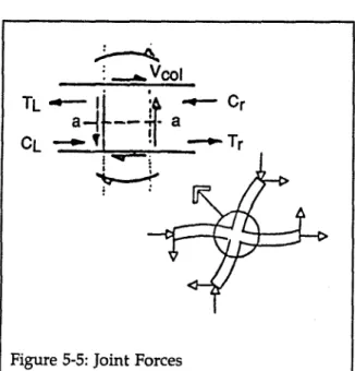
Column moments can be determined from column shears, Vc' by assuming hinges at mid-points of storey heights, with the exception of first-storey columns, where hinges should be assumed atVa the storey height. Beam moments at edge columns can be determined from the equilibrium of member moments at the beam-column connections, and at interior beam-columns from equilibrium of member moments of セィ・ beam-column connections and the relatIve stiffnesses of adjoining beams.
maximum storey shear at storey level j total number of storeys above ground level
number of storey levels under consideration
total seismic dead load of all storeys above level j (see Section3.3.1)
total seismic dead load base shear from Equation 3-4 where
セ
= = = Wj = W = V =The following drift ratio, applicable only to regular, multi-store)" multi-bay frames,isbased on the lateral deflection due to flexural displacement of a representative column, including the effect of end rotation due to bending of the representative girder.
Shearing Stress in Concrete Frame Columns The Quick Check of the average shearing stress, vav ' in the columns of concrete frames is
obtained f:.om: (3-8) nc Vj v = _ avg n -n A c f c (3-9) where DR= kb = kc = h = I = L
=
E=
drift ratio
=
interstorey displacement divided by interstorey heightIlL for the beam IlL for the column storey height, mm
moment of inertia (uncracked section for concrete members) mm4
centre-to-eentre length, nun modulus of elasticity, MPa
where
nc
=
nf=
Ac
=
total number of columns
total number of frames in the direction of loading
summation of the cross sectional area of all columns in the storey under consideration