DOCTORAT DE L'UNIVERSITÉ DE TOULOUSE
Délivré par :
Institut National Polytechnique de Toulouse (INP Toulouse)
Discipline ou spécialité :
Science et Génie des Matériaux
Présentée et soutenue par :
M. YU WANG
le vendredi 5 décembre 2014
Titre :
Unité de recherche :
Ecole doctorale :
AB INITIO CALCULATIONS OF H INTERACTIONS WITH DEFECTS IN
FCC METALS: CRACK TIP DISLOCATIONS AND VACANCIES
Sciences de la Matière (SDM)
Centre Interuniversitaire de Recherche et d'Ingénierie des Matériaux (C.I.R.I.M.A.T.)
Directeur(s) de Thèse :
M. ERIC ANDRIEU
M. DOME TANGUY
Rapporteurs :
M. LAURENT PIZZAGALLI, UNIVERSITE DE POITIERS
Mme MAYLISE NASTAR, CEA SACLAY
Membre(s) du jury :
1
M. ALEXANDRE LEGRIS, UNIVERSITE LILLE 1, Président
2
M. DANIEL MONCEAU, INP TOULOUSE, Membre
2
M. DOME TANGUY, UNIVERSITE LYON 1, Membre
2
M. ERIC ANDRIEU, INP TOULOUSE, Membre
2
M. NICOLAS COMBE, UNIVERSITE TOULOUSE 3, Membre
In many technological applications of structured metallic alloys, hydrogen embrittlement (HE) is a major concern as it can penetrate in most metals, degrade their properties and lead to premature failures. Despite numerous efforts in the past decades during which many microscopic mechanisms were proposed, a clear understanding of H embrittlement mechanisms has not been achieved yet. Since HE processes occur on an atomic-scale, the exact mechanisms leading to HE are not easily identified experimentally. One possible improvement would be to use atomic-scale simulations to try to capture details of deformation and fracture processes at the atomic level, enabling the investigation of relevant microscopic mechanism. In such context, the goal of this PhD work is to understand and quantify H interactions with defects like vacancies, dislocations and cracks in fcc metals through multi-scale modeling. The study is organized in four main parts.
In the first part, we employed first principle calculations (based on density functional theory) to describe H interaction with a vacancy in Nickel. More specifically, the segregation energies of multiple H atoms in a single and di-vacancies were computed. Two characteristic energies were found which clarify the experimental peaks observed in Thermal Desorption Spectra in the literature. The equilibrium concentrations of H-vacancy clusters was then evaluated, under con-ditions relevant to HE and stress corrosion cracking (SCC) of Ni based alloys (nuclear industry), by Monte Carlo simulations and a thermodynamic model developed from our DFT data. In the second part, we quantified the trapping effect of vacancies on H diffusion in Nickel. With DFT computed jump barriers, related to H trapping and de-trapping in vacancies, we employed accelerated Kinetic Monte Carlo (KMC) simulations to evaluate the H diffusion coefficient as a function of vacancy concentration and temperature.
In the third part, we studied the diffusion of H-vacancy clusters in Ni, based on the combination of DFT and a statistical method. DFT calculations of vacancy jump barriers were performed for clusters containing from one to six H inside the vacancy. With these computed barriers and previous calculated concentrations of H-vacancy clusters, a simple stochastic model similar to the KMC procedure was developed to estimate the diffusion coefficient of H-vacancy clusters as a function of H concentration and temperature.
In the last part, we studied the interaction of hydrogen with a blunted crack tip in Aluminum by combined EAM (semi-empirical interatomic potential) and DFT calculations. Embedded atom method (EAM) potential simulations were performed to evaluate the H effect on dislocation emission from a blunted crack tip under mixed mode loading. This phenomenon can be un-derstood by the H induced change of the unstable stacking fault energy (γus) in Rice’s model.
Therefore, DFT and EAM calculations of γuswere performed including the effects of H and of
the mixed mode loads. It is shown that the effect of the load perpendicular to the glide plane is very strong, contrary to the effect of sub-surface H, which is negligible.
Contents
1 Introduction and General Bibliography 1
2 Computational Methodology 11
2.1 Density Functional Theory . . . 11
2.1.1 Introduction . . . 11
2.1.2 The Many-electron Problem . . . 12
2.1.3 Hohenberg-Kohn Theorems . . . 13
2.1.4 The Kohn-Sham Equation . . . 15
2.1.5 Approximations . . . 16
2.1.5.1 Exchange-Correlation Functionals . . . 16
The Local Density Approximation . . . 17
The Generalized Gradient Approximation . . . 18
2.1.5.2 Crystalline Periodicity and Brillouin-zone Integrations . . . 19
2.1.5.3 Pseudopotentials . . . 21
2.1.6 VASP code . . . 23
2.2 Molecular statics : classical atomistic model . . . 23
2.2.1 Interatomic potential: Embedded Atom Method (EAM) . . . 25
2.2.2 Quenched dynamics: . . . 27
2.3 Monte Carlo simulations . . . 28
2.3.1 Monte Carlo method . . . 28
2.3.2 kinetic Monte Carlo . . . 30
2.3.3 Accelerated kMC : Mean Rate Method . . . 31
2.3.4 Transition State Theory . . . 32
3 Segregation of Hydrogen to Vacancies in Nickel 35 3.1 Introduction . . . 35
3.2 Calculation and Modeling Details . . . 38
3.2.1 DFT Calculations . . . 38
3.2.2 Monte Carlo Model . . . 39
3.3 Segregation of hydrogen to a single vacancy . . . 40
3.3.1 Preliminary Calculations . . . 40
3.3.1.1 Monovacancy . . . 40
3.3.1.2 Hydrogen in solution . . . 41
3.3.2 Interactions between hydrogen and a single vacancy . . . 42
3.3.2.1 V1H1 energetics . . . 43
3.3.2.2 V1Hm (m≤6 octa, m≤8 tetra) energetics . . . 45
3.3.2.3 V1Hm (m > 6 octa) energetics . . . . 47
3.3.3 Introduction to V2Hmclusters : the case of V2H1 . . . 48
3.4 Stability of Vacancy-Hydrogen Clusters . . . 49
3.4.1 Simplified energetic model of V1Hm . . . 50
3.4.2 Thermodynamics of Vacancy-Hydrogen Clusters . . . 51
3.4.2.1 “Out-of-equilibrium” approach . . . 51
3.4.2.2 “Full equilibrium” approach . . . 53
3.4.3 VH6-VH6 interactions . . . 56
3.5 Summary . . . 57
4 Effect of Interaction between Hydrogen and Vacancies on the Diffusion 59 4.1 Introduction . . . 59
4.2 Calculation and Modeling details . . . 61
4.2.1 DFT calculations . . . 61
4.2.2 KMC model . . . 62
4.3 H interstitial diffusion . . . 64
4.3.1 Analytical model . . . 64
4.3.2 H migration barriers: DFT results . . . 65
4.3.3 KMC-MRM results . . . 66
4.4 Hydrogen enhanced diffusion in nickel . . . 69
4.4.1 Diffusivity of vacancy-hydrogen clusters . . . 69
4.4.2 Vacancy migration and jump frequency: DFT results . . . 69
4.4.3 Vacancy diffusion . . . 72
4.4.4 Self-diffusion . . . 76
4.4.5 Cr diffusion in Ni-based alloys: vacancy mediated diffusion . . . 77
4.5 Summary . . . 80
5 Multiscale Simulation of Hydrogen Effect on Crack Tip Plasticity in Alu-minium 83 5.1 Introduction . . . 83
5.2 Calculation and Modeling details . . . 90
5.2.1 Crack simulation set-up . . . 90
5.2.2 DFT simulation setup . . . 93
5.3 Crack Simulation: Results and Analysis . . . 94
5.3.1 Mixed modes effect : pure metal case . . . 94
5.3.2 H effect on the crack tip behavior . . . 96
5.4 H stability during shear and diffusion in the glide plane . . . 100
5.5 H effect on the generalized stacking fault energy . . . 107
5.5.1 Details about the relaxations . . . 108
5.5.2 Results obtained with the EAM potential . . . 108
5.5.3 Results obtained from DFT . . . 111
5.6 Summary . . . 112
6 Conclusions and Perspectives 113
List of Figures
1.1 Comparison between the strain field obtained from image correlation (experi-mentally) and from crystalline plasticity modeling [1]. The grain structure was obtained by EBSD prior straining and meshed into the model. The sample was charged with hydrogen by cathodic polarization. H uptake occured from the sur-face presented here. After straining, cracks (marked by arrows) initiate along grain boundaries in between grains that are not well oriented for slip, but in a neighborhood which deforms extensively. The comparison of the strain fields val-idates the model, which is used in a second step to evaluate the local stresses. It was found that the stress on the GB facets, prior to fracture, were of the order of 170MPa while the macroscopic stress level was of the order of 120MPa (yield point 85MPa). . . 2
1.2 H redistribution in a polycristalline aggregate after straining (by continuum dif-fusion coupled to plasticity) [2]. . . 2
1.3 SEM image of the oxidation at the emergence of a slip band in fatigue (at imposed cyclic plastic strain amplitude) [3] obtained on 304L austenitic stainless steel in PWR environment. Each oxide layer corresponds to one cycle. . . 3
1.4 SEM images illustrating the impact of H on fracture in a hydride forming system (β Ti) [4]. (a) and (b) correspond to a H concentration of 1.4% while (c) and (d) correspond to 21%. Note the complete change of the fracture mode from ductile to quasi-cleavage. . . 4
1.5 A brittle intergranular crack in NiAl (courtesy of Ian Robertson, University of Illinois Urbana Champain). . . 4
1.6 Schematic representation of adsorbed H induced decohesion, from Lynch [5].. . . 7
1.7 Evolution of the surface excess energy (ideal work of fracture) as a function of the H coverage, for Al (resp. Fe) in the orientation {111} (resp. {110}) [6]. ML means “monolayer”.. . . 7
1.8 Post mortem TEM observation of the dislocation cell structure below the fracture surface [7]. The surface is protected, before FIB cuting, by a Pt deposit, which enables a fine inspection of the crack trajectory from the thin slices. It has never been observed that the crack deviates from the core of the GB, in spite of intense plasticity along the crack path. It should be mentioned that the macroscopic brittleness is strain rate dependent [8] and the present conditions where a strain rate of 4 10−4 s−1 with 2000appm internal H, without notch. These conditions
favor plastic deformation. These precisions are given only to mention that such an intense plastic deformation is not necessary to crack the GBs. . . 8
1.9 TEM image of the dislocation structure around a crack in fatigue in Fe-Si alloy in He atmosphere, from [9]. . . 8
1.10 TEM image of the dislocation structure around a crack in fatigue in Fe-Si alloy in H atmosphere, from [9]. . . 9
1.11 Schematic representation of the AIDE model (adsorption-induced dislocations-emission), from Lynch [5]. . . 9
2.1 Schematic diagram of “Jacobs ladder” of exchange-correlation functionals pro-posed by J. P. Perdew. . . 17
2.2 Schematic of the first Brillouin zone of FCC lattice with high symmetry points. The defined k-paths forms the wedge of the irreducible portion of the Brillouin zone. . . 21
2.3 Comparison of a wave-function in the Coulomb potential of the nucleus (blue dashed lines) to the one in the pseudo-potential (solid lines). The real and the pseudo wave-function and potentials match above a certain cutoff radius rc. . . 22 2.4 Schematic illustration of the calculation of KS-ground state in VASP.. . . 24
3.1 The experimental release results for 4.1016/cm2D implanted in single-crystal Ni at
10 keV compared with the result of the theoretical fit (upper solid curve). The dot-and-dash and the dashed curves indicate the temperature-dependent population of the two defect traps with binding enthalpies of 0.24 and 0.43 eV, respectively. The lower solid curve gives the theoretically expected release curve in the case where no traps are available., from [10]. . . 36
3.2 Thermal desorption spectrum of Ni after heat treatment at 950oC, p
H=3GPa for
2 h, from [11, 12].. . . 36
3.3 Lattice parameter changes over a whole run aimed at measuring the temporal variation at 896oC and p(H
2) =3 GPa[13]. . . 37
3.4 Magnitude of the lattice contraction measured at different temperatures and H pressures (left-hand scale).[13]. . . 38
3.5 A vacancy in a fcc structure surrounded by the first and second shell of octahedral sites (6 O1 and 8 O2 sites) and only one, out of 8, T1 tetrahedral interstitial site
represented (white ball). . . 39
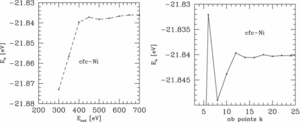
3.6 Evolution of the total energy of fcc-Ni versus the cut-off energy (left) and the number of k-points (right). . . . 39
3.7 Projected force field obtained when, after relaxation, the atom is put back into the vacancy (an arrow length of 1 represents 0.5 eV/Å). The vacancy is located at (0,0). Triangles and circles represent {200} planes. Arrows represent the forces on atoms, their lengths are proportional to the norm of the strengths. . . 41
3.8 Schematic of the dodecahedra around the vacancy (in rose). . . 42
3.9 Schematic of the different positions of the H atoms inside and in the vicinity of the single vacancy: On top, the 5×3×3 supercell and, at the bottom, the 3×3×3 supercell. The position of the vacancy is colored in blue. Labels correspond to the letters used in Table 3.3. . . 43
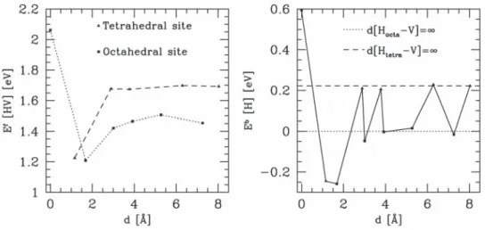
3.10 Evolution of the formation (top) and segregation (bottom) energy according to the distance between the H atom and the vacancy. . . 45
3.11 Schematic of the optimized VH6 configurations (left), and VH6 (right), the H
atoms are in the tetrahedral and octahedral sites, respectively. The smallest ball are the H atoms. . . 45
3.12 Mean segregation (hEi) energies (left) and segregation (Eseg) energies (right) according to the number of H atoms in a vacancy. Squares and stars represent octahedral and tetrahedral configurations, respectively.. . . 47
3.13 Schematic of the different hydrogen positions around a divacancy (1NN). . . 48
3.14 Schematic of the different hydrogen positions around a divacancy (2NN). . . 48
3.15 Variation of the vacancy site occupancies as a function of the bulk H content COb (Cmobilehydrogen) at T=300 K (left) and 600K (right), obtained by the Mean Field
equations (mf) and by Monte Carlo simulations (mc) using the energetic model from DFT. . . 52
3.16 Distribution of V Hn clusters at T=300 K (left) and 600K (right). Symbols cor-respond to Monte Carlo simulations and lines corcor-respond to equations 3.16. . . . 55
3.17 Variation of the cluster concentration (added to the thermal vacancy concentra-tion) at T=300 K (left) and 600K (right). . . 55
3.18 Variation of the cluster concentration (added to the thermal vacancy concentra-tion) at T=1200K. . . 56
4.1 Concentration profiles of Cu after diffusion annealing for 30 min at (a) 600oC, (b) 700oC, (c) 750oC, and (d) 800oC, in 5 GPa of hydrogen, and (e) 700oC under a mechanical pressure of 5 GPa, from [14]. The zero of distance is taken at the Boltzmann-Matano interface. . . 60
4.2 Interdiffusion coefficients in Cu-Ni alloy. The upper group of curves is the exper-imental data obtained in 5 GPa of hydrogen, and the lower group reported data obtained under ordinary conditions[14]. . . 60
4.3 Illustration of NEB simulation: exchange of a metal atom with a neighboring vacancy. . . 62
4.4 Schematic of the state connectivity.. . . 63
4.5 Illustration of interstitial sites around a vacancy (gray ball) in fcc lattice. O1(olive
green ball) and O2 (green ball) are the first (1NN) and second (2NN) nearest
neighboring octahedral site to the vacancy, respectively. T1 (blue ball) and T2
(violet ball) are 1NN and 2NN tetrahedral sites, respectively. Note that T2 are
considered as the bulk sites in the simulations. . . 65
4.6 Illustration of the energy landscape [15] between adjacent octahedral and tetra-hedral sites. . . 66
4.7 Comparison of experimental and theoretical bulk diffusion coefficients of H in Ni, without traps [15]. . . 67
4.8 Computed and theoretical diffusion coefficient of H in pure Ni (black), and for two CV ac: 31 (red) and 1160 (olive) ppm. . . 68 4.9 The ratio of Def f on DL is given as a function of CV ac: comparison between
KMC simulations and the trapping model and effect of the number of trap sites considered in the lattice model. . . 69
4.10 A vacancy (light gray ball) in an fcc structure is surrounded by 6 octahedral first neighbors (O1), 8 tetrahedral first neighbors (T1) and 8 octahedral second
neighbors (O2). . . 70
4.11 Schematic illustration of low barrier vacancy jumps. The vacancy position is represented by a light gray ball while H in O1 and T1 positions (Fig. 4.10) are
represented by smaller balls. The different jump pathways are indicated by arrows for each V Hn configuration. . . 72 4.12 Schematic illustration of migration path for the migration of Ni atoms in VH2:
on Fig. 4.11(c), path(a). . . 73
4.13 Schematic illustration of migration path for the migration of Ni atoms in VH4:
on Fig. 4.11(i), path(a). . . 73
4.14 (a) Vacancy diffusion coefficients in pure Ni (D0
vac) and in hydrogenated Ni (Dvacef f at CH = 10 and 1000 ppm). The contribution of each cluster to the diffusivity at
CH= 1000 ppm is also shown. The lower graph presents the relative errors in the vacancy diffusion coefficient for at CH = 10 and 1000 ppm (see text for details on the truncation of Eq. 4.9). (b) For comparison, the distribution of V Hnclusters as a function of temperature at CH = 1000 ppm is plotted from the thermodynamic model in [16]. . . 75
4.15 (a) Vacancy diffusion coefficient as a function of cH, at 300 K, in pure Ni and in hydrogenated Ni. The contribution of each cluster to the diffusivity is also shown (upper graph). The relative error, due to the truncation of Eq. 4.9, is given on the lower graph. (b) same as (a) but for T=600 K. . . 75
4.16 Activation energy and prefactor for the diffusion of vacancies, as a function of CH, obtained by fitting Def f
vac to the Arrhenius form for T ∈ [300, 600]K. . . . 76 4.17 (a) Ni self-diffusion coefficients in pure Ni and in hydrogenated Ni (CH = 10 and
1000 ppm). The contribution of each cluster at CH = 1000 ppm is shown on the upper graph. The relative errors for CH = 10 and 1000 ppm are presented in the lower graph. (b) Self-diffusion coefficient at T=600 K, as a function of cH.. . . . 77 4.18 Activation energy and prefactor for Ni self-diffusivity as a function of CH, obtained
by fitting Def f
4.19 Pressurecompositiontemperature phase diagram of the NiH system. Results of heating runs H1 (•) and H2 (N), cooling runs C1 (△) and C2 (◦). Pressures in each run measured at room temperature, ≃400oC and the highest temperatures are, respectively, H2 (4.34.65.4 GPa), C1 (1.52.12.4 GPa), H1 (1.92.12.2 GPa), and C2 (1.11.42.1 GPa). An isobar labeled C∗illustrates (schematically) the expected
temperature dependence at a lower pressure (< 1 GPa). from [17]. . . . 80
5.1 Schematic picture of a dislocation free zone (DFZ). Top figure: plastic zone ob-tained by 2D discrete dislocation dynamics [18], each point represents a disloca-tion; the crack tip is at x=0, y=0. Bottom: a schematic zoom of the distribution of the dislocations emitted at the crack tip. The shielding dislocations are re-pelled from the crack tip at pile up at a distance ahead of it. The region free of dislocations is of nanometer size and obeys elasticity. The stress there is singular, with a stress intensity factor which depends on the applied external load and the position of all the dislocations in the system (each of them creates a stress field which acts on the crack tip). . . 84
5.2 2D loop emission (in mode II) from a crack tip [19]. . . 85
5.3 Crack configurations studied in [20]. (a) In pure Al, dislocations are emitted perpendicular to the crack plane, in mode I. (b) and (c) illustrate the influence of H adsorbed in bridge (B-site) and top (T-site) positions on the crack flanks. The same is done for fracture (e) and (f) with spectacular differences found. . . 87
5.4 Comparison between adsorbed H and O on dislocation emission at a crack tip (see text for the precise orientation). In both cases, emission require a higher load than in pure Al. Furthermore, H involves a reconstruction of the crack tip during emission that modifies the plane where the dislocation is emitted [21]. . . 88
5.5 Generelized stacking fault energies from [22] showing the energy variation when H occupies a tetrahedral site (resp. octahedral) represented by circles (resp. squares). 88
5.6 Generelized stacking fault energies from [23], showing the energy variation for a glide in the plane containing H (GSF1), the nearest neighbor plane (GSF2) and the next ,nearest plane (GSF3). The reference without H is also shown. . . 89
5.7 Schematic of the simulation box with an embedded crack. . . 91
5.8 (a) Displacement profiles in the traction direction, in the case of pure mode I (“no shear”) and with a super-imposed shear in the y direction (“shear”). (b) and (c) are the corresponding stress profiles (σzz in mure mode I and σyz in mixed mode I+II. The curves represent the fits to Eq. 5.2 and Eq. 5.3 that where used to extract the values of kI and kII. The Virial stress is multiplied by the atomic volume and the values are given in eV, the correspondence to GPa is obtained by multiplying the values by 9.8. . . 92
5.9 Crack configurations before and after the dislocation emission on the crack plane. The plastic shear is highlighted by the atom pairs in dotted lines. . . 95
5.10 (a) Horizontal displacement ∆uy as a function of the y position for crack tips under critical load just before dislocation emission. (b) Horizontal and (c) vertical displacement (∆uy, ∆uz) as a function of the y position during the nucleation of Shockley partial dislocations, for the case of kI = 0.045 M P a√m in mixed modes. (d) Increase of the crack tip opening for crack tips under critial loads of pure mode I, mixed modes, and mixed modes with H. . . 96
5.11 Shear stress field of the simulation box project on (110) plane : (a) small shear load (b) critical shear load (c) dislocation emissions emitted symmetrically from the two crack tips. . . 97
5.12 Schematic of the crack tip at the right side, with marked tetrahedral positions (blue balls) for the insertion of H.. . . 98
5.13 (a) Projected atom displacement field on the (110) plane, induced by the presence of the H line on position 1. The starting point of the vectors are the relaxed positions without H, while the end of the vectors is the relaxed positions in the presence of H. The vector length is enlarged by a factor of 5. The red filled circle is the relaxed H position. The crack tip is under mixed loads where kI = 0.099
M P a√m. (b) Project atom displacement field relevant to the very beginning of
the relaxation when H occupies position 2 (red empty circle). (c) Projected atom displacement after full relaxation when H occupies position 2. (d) Project atom displacement field when H occupies position 3. . . 99
5.14 (a) Horizontal and (b) vertical displacement as a function of the y position during the nucleation of Shockley partial dislocations. The profiles labeled k−
IIe corre-spond to a mechanical load just below the one for dislocation emission.. . . 100
5.15 Side view (upper picture) and top view (lower picture) of the glide plane showing: the top Al layer, that is to be translated to the right to form an intrinsic stacking fault; the bottom layer which is held fixed and the three different interstitial positions in the glide plane T+, T- and O. At each value of the shear, the first neighbors of the H atom are fully relaxed, while all other Al atoms are fixed. . . 101
5.16 The Al atoms are shown in their final position where the ISF is created. The small circles represent the successive H position during the shear, starting from the three positions of the fcc structure (Fig. 5.15): T+(fcc), T-(fcc) and O (fcc). The final positions are respectively O(hcp), O(hcp) and T-(hcp). . . 101
5.17 Segregation energies for H on T+(fcc) and O(fcc) sites as a function of the shear:(a) ∆uz=0;(b) uz=0.05 a0 . . . 102
5.18 Energy profiles obtained by the NEB for jumps T+→T-(1) and T+→O(1), at two different levels of shear. . . 103
5.19 Schematic picture of the various diffusion path in the fcc structure and in the local hcp structure of the ISF.. . . 104
5.20 Evolution of the energy barrier for the various H jumps as a function of the shear obtained using the EAM potential: (a) for jumps from T+/T- sites; (b) for jumps from O site; (c) and (d) similar to (a) and (b) respectively, but with an increase of interplanar distance ∆uz on the shear plane. . . 105 5.21 Diffusion path in the fcc and hcp (ISF) structures. . . 106
5.22 Energy profiles for obtained by the NEB for T+→O(1) jump (a) and T+→T-(1) jump at different levels of shear ∆uy and opening ∆uz. . . 106 5.23 EAM and DFT computed unstable stakcing fault energy as a function of ∆uz in
the pure Al. . . 109
5.24 The generalized stacking fault energies as function of a shear long h112h direction in Pure Al for different values of ∆uz. . . 109 5.25 Variation of γusas a function ∆uz(the opening) for different levels of H coverage,
in EAM and in DFT.. . . 110
5.26 Variation of γus as a function ∆uz (the opening) for different H coverage and different relaxation methods in DFT. ZR refers to relaxations in z only of the Al toms of the two first layers around the glide plane. LR refers to a local relaxation where Al atoms within a sphere of 0.73 a0.. . . 111
6.1 Normalized stress intensity factor as a function of H coverage. ke is normalized to the value of kpure
List of Tables
3.1 Formation energies (Ef
1v, in eV) and volumes of formation (Ω
f
1v, in atomic volume)
of the single vacancy. . . 40
3.2 Insertion (Ei[H], in units of eV) and solubility (Es[H], in units of eV) energies, H frequencies (ω, in cm−1) and zero-point energies (ZPE, in meV) of the H atom in
fcc nickel. ∆E corresponds to Es[Xsite] − Es[Osite].. . . 42 3.3 Formation (Ef, in units of eV, without ZPE) and segregation energies (Eseg, in
units of eV) of V1H1 cluster according to the distance between the H atom and
the vacancy. We give the vacancy-hydrogen distances and the site where the H atom is located. Notation: V = vacancy, T = tetrahedral site and O =octahedral site, see Fig. 3.9. . . 44
3.4 Degeneracy, formation, mean segregation and segregation and formation energies (in eV) and magnetic moment (µB, in Bohr’s unit) of the V1Hmclusters. For the segregation energy, the number of the H atom removed is given in brackets. . . 46
3.5 Segregation and formation energy (in eV) of the V1Hmaccording to the number of H atoms in the cluster. . . 47
3.6 Formation and segregation (here hEi = Eseg) energies of one H atom in 1NN. Energies are presented in units of eV. For hydrogen in octahedral sites (1NN), the case 1=2, 14=7, and 15=5. . . 49
3.7 Segregation energy (∆Eseg in eV), for the bringing a H from a bulk site on a O
2
position in the V Hn−1configuration. . . 51
3.8 The number of hydrogen involved in the cluster (k), the cluster configuration, the corresponding formation energy (EV Hk
f in eV) and the number of variants (nV Hk) are presented. . . 54
4.1 Jump barriers ∆Gm(eV) (row (initial state) → column (final state)) for H in the vacancy and in the bulk calculated by the NEB method. ZPE corrections are included.. . . 66
4.2 Degeneracy and barriers for the different pathways of each relevant cluster con-figuration. The letters in the third and forth columns correspond to the indices of the jump pathways shown in Fig. 4.11, and the alphabetical order corresponds to the decrease of the distance between the exchanged Ni atom and the multiple H of the vacancy (see text for a discussion of this criterion to select, a priori, the paths having low energy barriers). . . 71
4.3 Activation energies (in units of eV) and prefactors (in units of m2s−1)
correspond-ing to the V Hn diffusivities, obtained by fitting Dvacn to the Arrhenius form.. . . 74 4.4 Some migration energies (in units of eV) of Cr and Ni atoms in VH0, VH1and VH4. 79
5.1 Results of the crack simulations under mixed mode I and mode II load. k units are in MP a√m. . . . 98
5.2 Comparison of barriers computed by full relaxation and local relaxation. The calculations are performed in undistorted fcc structre and ISF structure. The unit is eV. . . 105
5.3 DFT computed segregation energies and jump barriers for H by local relaxation. The unit is eV. . . 107
5.4 kIIe values (in MP a√m) obtained by brute force QMD simulations using the EAM potential (column ”EAM potential“); tabulated using the Rice formula Eq. 5.1 from γus calculated by EAM (column ”Rice (EAM)“) or by DFT (col-umn ”Rice (DFT)“). . . 110
Introduction and General
Bibliography
The context of this thesis is the stress corrosion cracking (SCC) of face centered cubic metallic alloys. SCC is a problem of technological relevance to structural alloys because this phenomenon (or the related fatigue-corrosion) is the source of most materials failure in service. The safety issue implies an economical cost related to the periodic inspection of structures to detect small cracks, the monitoring of their growth and finally the maintenance of the installations. The research issues are: to understand the mechanisms that govern cracking of existing alloys, to predict crack initiation and growth and to optimize composition and microstructure of future alloys for a better resistance. Of particular interest for this study are two applications: (i) Ni based alloy 600 is used for some parts of the primary circuit of pressurized water reactors. It is susceptible to show intergranular SCC. The corrosive medium is high temperature (about 600K) pure water under pressure. The issue is to predict SCC initiation and propagation in relation to life extension of civilian nuclear plants. (ii) High strength AlZnMg alloys (7XXX family) are used in the aircraft industry for structure parts. Now, it is also an objective to use it for automotive applications at a large scale (not only premium vehicles). Its high mechanical properties enable the reduction of the thickness of the pieces that would induce substantial weight gains in the vehicles. Unfortunately, it is extremely sensitive to intergranular SCC, so far, and future applications would require the development of new compositions (additions to Zn and Mg solutes) and optimization of intergranular precipitation. These applications constitute the motivation to work on two face centered cubic metals: Ni and Al.
In this context, there is a clear need to understand the mechanisms that rule SCC. This has been the subject of applied academic research for many years. The outcome is rather destabilizing at first sight because of the massive amount of material/corrosive medium specific data that have been produced. The large number of parameters and their complex interplay make the analysis of the results and the design of simplified experiments difficult. We will not review here all the data related to the specific systems we mentioned above. These can be found in dedicated PhD thesis (like Laghoutaris - Mines de Paris 2009 and Jambon - Université d’Evry 2012 for alloy 600 and Ben Ali - Mines de Saint-Etienne 2011 for AlZnMg). Instead, we give here an overview of the possible microscopic mechanisms by reviewing some of the models that have been proposed,
based on experimental observations. While doing so, we include the most recent small scale observations, or ab initio calculations, to highlight the relevance of certain mechanisms or put a distance to those that seemed to be the most appealing at the time of the formulation of the model. In any case, fine scale observations illustrate the complexity of the phenomena and underline the crucial need of sound, physically based, modeling. A specific bibliography will be given at the beginning of each chapter, and should provide the necessary complement to the generalities presented below.
Figure 1.1: Comparison between the strain field obtained from image correlation (experi-mentally) and from crystalline plasticity modeling [1]. The grain structure was obtained by EBSD prior straining and meshed into the model. The sample was charged with hydrogen by cathodic polarization. H uptake occured from the surface presented here. After straining, cracks (marked by arrows) initiate along grain boundaries in between grains that are not well oriented for slip, but in a neighborhood which deforms extensively. The comparison of the strain fields validates the model, which is used in a second step to evaluate the local stresses. It was found that the stress on the GB facets, prior to fracture, were of the order of 170MPa
while the macroscopic stress level was of the order of 120MPa (yield point 85MPa).
Figure 1.2: H redistribution in a polycristalline aggregate after straining (by continuum diffusion coupled to plasticity) [2].
Let’s first list the parameters involved in SCC to illustrate the complexity of the problem and then simplify it by making the link with the sub-problem of hydrogen embrittlement. SCC is transversal to three fields: materials, chemistry (corrosion) and mechanics. The macroscopic parameters are therefore those of these three components: (i) materials aspects are wide because they cover the composition, which impacts the electrochemical potential, the nature of the oxide layer... and also the microstructure: intergranular precipitation/segregations influences localized corrosion; intragranular precipitation modifies plasticity, stress levels... (ii) the corrosive medium is also represented by its composition (chlorides in aqueous media, wet/dry air, solution
confinement), by the overall electrochemical potential which can favor anodic dissolution or cathodic reactions, the nature of the oxide film... (iii) the mechanical load has a strong impact. Macroscopically, the key parameter is the strain rate. Indeed, the environment is often more deleterious when active plasticity periodically emerges at the surface where it can interact with corrosion. All sorts of mechanical tests are used: slow strain rate traction, constant stress (creep at room temperature is equivalent to extremely slow traction), constant K, bending, fatigue... Ultimately, the macroscopic mechanical load should be transformed into stress-deformation maps at the scale of the grain, since deformation is quite heterogeneous in a polycristal. This is what is currently done by coupling crystalline plasticity models, on polycrystalline aggregates, to local field measurements. Then it is possible to relate crack initiation, on the surface, to more physical stress and strain levels (Fig.1.1and1.2). So far, this kind of research is limited in the field of SCC but is developing. On top of the complexity related to the number of parameters are the numerous synergies between the different aspects. As an example of corrosion-deformation interaction: slip emerges at the surface or on a crack lips, breaks the oxide layer and the bare metal at the level of the slip step corrodes. Some byproducts of the oxido-reduction reactions penetrate the material (hydrogen, vacancies), which interact with dislocations. The outcome is a modification of the density of dislocations in the slip bands, an enhancement of their multiplication... which, in turn leads to more localized plasticity emerging on the surface (Fig. 1.3). This thesis deals with hydrogen embrittlement, which can be seen as a sub-problem of SCC, but nonetheless very challenging. Indeed, corrosion of metals in aqueous media (liquid or wet gas) produces hydrogen as the oxidation of metal is coupled to, primarily, the reduction of oxygen if it is present and/or to the reduction H+ coming from the dissociation of water in the liquid or adsorbed water
molecules in the gas phase. It is now widely accepted that a fraction of this H is absorbed in the material and participates in fracture. This motivated studies of the impact of hydrogen alone on materials’ properties.
Figure 1.3: SEM image of the oxidation at the emergence of a slip band in fatigue (at imposed cyclic plastic strain amplitude) [3] obtained on 304L austenitic stainless steel in PWR
environment. Each oxide layer corresponds to one cycle.
Regarding hydrogen impact on fracture, the primary concern is that it promotes brittle fracture of ordinarily ductile material. Figure 1.4shows experimental results of a H triggered transition from ductility to quasi-cleavage in Ti, at room temperature. Another example is the brittle intergranular fracture of intermetallic NiAl in the presence of H. The TEM shows that plasticity is almost absolutely absent and the crack sharp (Fig.1.5). Note that we have deliberately given an example of transgranular and intergranular fracture. For transgranular, we make a distinction
Figure 1.4: SEM images illustrating the impact of H on fracture in a hydride forming system (β Ti) [4]. (a) and (b) correspond to a H concentration of 1.4% while (c) and (d) correspond
to 21%. Note the complete change of the fracture mode from ductile to quasi-cleavage.
Figure 1.5: A brittle intergranular crack in NiAl (courtesy of Ian Robertson, University of Illinois Urbana Champain).
between clevage and quasi-cleavage which name comes from the flat facets, of the order of 1µm long, observed in scanning electron microscopy (SEM). People consider that cleavage is a true debonding, like in Si, along planes of low density, while quasi-cleavage is the result of intense and localize plasticity: one active slip band emerging at the crack front. This difference reflects in the models proposed. They are four, in the literature, which try to explain how H impacts fracture. We are going to review the main ideas that withstand them. More information can be found in review papers [5, 24, 25], also including references concerning experiments that originally supported the models.
by attracting electrons from the neighboring atoms (Fig.1.6). Proposed in the 60’s[26], some support of this idea came recently from ab initio calculations. They show, for simple surfaces, that indeed H decreases the ideal work of fracture (the difference in energy between the bonded crystal and two free surfaces covered by H). Figure1.7gives the variation of the energy with the H coverage for Al and Fe [6]. A similar trend was shown by Van der Ven for the cohesive stress [27]. Note that the surface coverage should be large. This is a problem because the driving force to localize H, in this model, is supposed to be elastic (the stress triaxiality) and this gives a modest factor 2 in between bulk concentrations and local concentrations [24]. This is not enough, in non hydride forming systems (where H-H is attractive), to reach high local concentrations that could significantly decrease cohesion. • Hydrogen Enhanced Localized Plasticity (HELP) is supported by in-situ observations of cracks, in the environmental TEM, in the presence of H2 gas. The authors observe crack
propagation upon the rise of H2 pressure by movement and emission of dislocations in
front of the tip of blunted cracks. The connection with quasi-cleavage is tentative. The generalization of the observations made on thin samples (submitted to the irradiation of the TEM beam) to fracture in bulk systems is debated [5]. In particular, propagation along the core of grain boundaries was never observed. Instead, it was seen, for example in Ni [28], that transgranular cracks are deflected by grain boundaries and propagate parallel to the GB, with the same plastic mechanism as in the bulk. The authors argued that intergranular cracking, which seemed to be brittle in scanning electron microscopy (SEM), were in fact the result of localized plastic activity in the vicinity of the GBs. Recently, modern TEM techniques (post mortem FIB slicing on intergranular fracture surfaces) revealed, on the same system, that crack propagation occurred indeed along the GB core and that, even if plasticity was intense, it formed cells in the vicinity of the GB (Fig.1.8). This sheds some doubts on the relevance of the mechanisms observed in situ for cracking of massive samples. Other recent experiments [9] show that the general idea behind HELP do correspond to reality. Crack propagation experiments in fatigue in Fe-Si single crystals along {110} were conducted in He or H gas. The TEM pictures of the dislocation structure around the crack tip are shown in Fig.1.9and1.10for He and H respectively. The difference is quite striking: H reduces the overall quantity of dislocations emitted, yet crack propagation occurs because of dislocations injected from the tip and at a faster rate in the H atmosphere. This points towards an enhanced localization of slip.
From the modeling side, HELP was supported by elastic calculations of the shielding, by the H atmosphere, of the elastic interactions between dislocations. Again, the origin is in-situ TEM where a pile up (in Al) was observed at different pressures of H2 gas. It was
seen that rising the pressure decreased the interdislocation distances in the pile-up. The effects was qualitatively well reproduced by elasticity: H segregates in the region of high triaxiality of the edge dislocations and the Cotterell atmosphere creates an elastic field similar to an edge dislocation of the opposite sign, but with a smaller Burger’s vector [29], hence decreasing the edge-edge dislocation interaction. These elastic calculations were recently questioned by atomic scale simulations which do not report the same intensity of shielding [30]. Indeed, the H concentration is unknown in the TEM samples and usually the elastic effects are small in magnitude.
• The “adsorption-induced dislocation-emission (AIDE)/void-coalescence mechanism” was proposed to explain transgranular liquid metal embrittlement, or intergranular in the case where no penetration occurs. It was extended to hydrogen effects based on some similarities of the fracture experiments. The major idea is that H adsorbs at the surface (or at the immediate sub-surface), weakens the bonds, and favor dislocation emission. This blunting is the first source of crack advance. The second step is more difficult to follow: dislocations, emitted at the crack tip, glide away from the crack and activate Frank Read sources. These sources emit dislocations on secondary slip systems (symmetric to the crack plane?) that intersect on the crack plane and give birth to cavities. Or, the plastic activity from the crack tip creates loads of vacancies that condensate in the crack plane and form cavities. The second reason for crack advance is the growth and coalescence of these cavities with the main crack (see Fig.1.11). The second main idea, which is based on observation of fracture surfaces, is that they are finely dimpled. Therefore, the fracture mechanism should be based on cavity formation and coalescence instead of decohesion.
• More recently, vacancy-hydrogen clusters have been considered as a possible source of embrittlement. First, Fukai discovered, when exploring metallic hydrides phase diagrams [31], that hydrogen can stabilize vacancies. The effect can be spectacular with vacancy concentrations reaching 25% in Ni (they reported an ordering of the vacancies in the L12
structure). The presence of vacancies, that was first seen on the lattice parameter (it was smaller than expected due to lattice dilatation of interstitial hydrogen), was later demonstrated directly in by TEM observations of dislocation loops and cavities upon heat treatment to desorb H and condensate vacancies. The physical origin is the large binding between H and the vacancy. It was seen in many metals: Fe, Al, Ni, Cu, Mo, Pd... (see table 5.10 in [31]). In addition, vacancies can be occupied by several H. Depending on H chemical potential. The vacancy formation energy can therefore be compensated by the energy gain related to multiple trapping and very high concentrations of clusters can be stable.
Since then, several groups have demonstrated the possibility of forming VHn clusters (a
vacancy with n segregated hydrogen) during electrochemical charging at room tempera-ture, in austenitic steels [32], in electrodeposited Cu [11], in pure Al [33]. The method is always similar, after charging a heat treatment is used to precipitate the vacancies and TEM observations are performed. However, a relation with H damage is not established, even though the connection with electrochemical reactions is convincing. Another way to introduce vacancies at low temperature is by extensive plastic deformation of the material. In ferritic steel [34], Nagumo has shown that the positron annihilation signal, that is at-tributed to vacancies, is stabilized by the presence of H. He proposes a mechanism where vacancies are stabilized by hydrogen and contribute to ductile fracture, or quasi cleavage, by enhancing the formation of very fine dimples. The case of ferritic steel is interested because it can be confronted to ab initio calculations in α Fe. The binding energies [35] for the first H are of the order of 0.6 eV (to be compared to a vacancy formation energy of 2 eV). The occupancy is therefore large at typical concentrations where embrittlement is observed (cb< 50ppm). It was shown that the VHn clusters have the tendency to form
linear chains and platelets, which were considered as potential weakening points [35]. The mobility of VnH1 clusters was recently studied [36]. It was shown that even a single H
0.7 eV, while it is 0.76 eV in the presence of a single H. The barrier for the H to jump out of the vacancy is 0.64 eV which tends to show that free vacancies are more mobile than clusters. This puts in perspective the model proposed in [34] and [35]. In a Ni based alloy, a similar role of plastic deformation induced vacancies in the loss of mechanical properties of the grain boundaries was proposed [37]: plasticity generates VHn clusters that diffuse
to the GBs and weaken them. By desorbing H at 200◦C, the authors show that the GB
damage remains, and therefore attribute the damaging to vacancies instead of H directly. This motivates our interest for studying the mobility of VHn clusters in Ni.
Figure 1.6: Schematic representation of adsorbed H induced decohesion, from Lynch [5].
Figure 1.7: Evolution of the surface excess energy (ideal work of fracture) as a function of the H coverage, for Al (resp. Fe) in the orientation {111} (resp. {110}) [6]. ML means
“monolayer”.
Finally, we would like to contribute to the field of HE, on the mechanistic side, by performing quantitative atomistic simulations of two elementary processes: (i) the vacancy-H interaction and (ii) the H-dislocation interaction at the crack tip. These should shed some light on processes that are mentioned in the models presented above, but, beyond this, could be useful for the future modeling of HE of fcc metals. More precisely, chapter 3 presents the static interaction of H with vacancies in Ni: from basic segregation energies to the development of a thermodynamic model for calculating the equilibrium concentrations of VHn clusters as a function of Cbulk (the
H concentration on an octahedral site in the ”bulk“, i.e. in the perfect crystal; also called Cmobile hydrogen or CH) and T (the temperature). Chapter 4 addresses ”dynamic“ interactions:
the impact of vacancies on the mobility of H is modeled and the reverse, the influence of H on the vacancy mobility is also studied. Finally the effect of VHn on the Ni and Cr mobility
is evaluated. Chapter 5 deals with the influence of sub-surface H on dislocation emission at a crack tip loaded in mixed mode I and II (i.e. tension and shear). Finally, the main results are summarized in the conclusion and a few perspectives are given.
Figure 1.8: Post mortem TEM observation of the dislocation cell structure below the fracture surface [7]. The surface is protected, before FIB cuting, by a Pt deposit, which enables a fine inspection of the crack trajectory from the thin slices. It has never been observed that the crack deviates from the core of the GB, in spite of intense plasticity along the crack path. It should be mentioned that the macroscopic brittleness is strain rate dependent [8] and the present conditions where a strain rate of 4 10−4s−1with 2000appm internal H, without notch.
These conditions favor plastic deformation. These precisions are given only to mention that such an intense plastic deformation is not necessary to crack the GBs.
Figure 1.9: TEM image of the dislocation structure around a crack in fatigue in Fe-Si alloy in He atmosphere, from [9].
The requirement of quantification of the effects motivates the use of ab initio methods. But, in practice, DFT calculations are heavy so it is useful to make first trials with a lighter method (for example H-vacancy binding and barriers where systematically calculated first with an EAM potential). Furthermore, equilibrium and kinetic Monte Carlo were used to establish numerical solutions for VHn distributions and H diffusion in the presence of traps. These references were
used to control the analytical models. For the crack problem, part of the information comes directly from atomic scale simulations, i.e. we trusted the potential to give reliable (they were tested) displacement fields in the vicinity of the crack tip. These fields were used for GSF calculations. These different methods (ab initio/classical atomistics) are introduced in chapter 1.
Figure 1.10: TEM image of the dislocation structure around a crack in fatigue in Fe-Si alloy in H atmosphere, from [9].
Figure 1.11: Schematic representation of the AIDE model (adsorption-induced dislocations-emission), from Lynch [5].
Specific bibliography, in complement of the generations presented above, is given at the beginning of each chapter.
Finally, the main results are summarized in the conclusion and a few perspectives are given (fast diffusion along dislocation cores / SaV formation along simple grain boundaries).
Computational Methodology
In this chapter, we present the tools used: ab initio calculations, Molecular statics using an empirical interatomic potential and Monte Carlo simulations.
2.1
Density Functional Theory
2.1.1
Introduction
The formulation of the Schrödinger equation in the 1920s opens the doors to investigate the quantum mechanical properties of material systems without depending on empirical or experi-mental input. All physical characteristics could be determined by the exact application of the Schrödinger equation to the system, based on the sole knowledge of the constituent atoms. How-ever, the Schrödinger equation cannot be solved exactly for systems containing more than two mutually interacting particles. Various numerical approaches to obtain approximate solutions have been proposed and developed over the years, like the perturbation theory, the variational method, the Quantum Monte Carlo (QMC) method, and WKB approximation and semi-classical expansion etc., making calculations involving a many-body Hamiltonian tractable with an ac-ceptable accuracy. Among these methods, the Density Functional Theory (DFT) is the most widely used, due to its good balance between a high accuracy and low computational costs which allows it to deal with large systems (up to hundreds of atoms or even more), when compared to the less efficient (but usually more accurate) wave functions based methods (e.g., QMC, coupled cluster theories).
DFT was conceived from Thomas-Fermi model proposed immediately after the foundation of quantum mechanics in 1927, and has been a primary method in the numerical simulation of condensed matter since the 1970s when Hohenberg, Kohn and Sham established the rigorously theoretical foundation for DFT. The main objective of DFT is to reduce the complexity of the many-body problem (3N spatial coordinates of N interacting electrons) by using the electron density (only three spatial coordinates) to describe the intricate many-body effects within a single particle formalism. In the following section, some general physical basis necessary for an overall understanding of DFT are presented. Comprehensive interpretation and discussion of
DFT can be found in a number of excellent review articles [38,39,40,41,42,43,44] and books [45, 46, 47,48].
2.1.2
The Many-electron Problem
The dynamics of a quantum system is governed by the Hamiltonian ˆH. If |Ψi is the stationary
state of the system, particularly the ground state, |Ψi is obtained by solving the time-independent Schrödinger equation
ˆ
H |Ψi = E |Ψi (2.1)
In the Hilbert space with the spatial coordinates as the continuous basis, for a system containing
M nuclei and N electrons, the wave-function Ψ of the system is a function of all the coordinates
of nuclei ({Rm} , m = 1, . . . , M) and spatial and spin coordinates of electrons ({rn, σn} , n =
1, . . . , N ). The Hamiltonian ˆH acting on Schrödinger wave-function Ψ is a sum of electronic and
nuclear kinetics and all interactions between electrons and nuclei given as (e = 1; ~ = 1) ˆ H = − N X n=1 ∇2 n 2me− M X m=1 ∇2 m 2M + N X n=1 N X n′>n 1 |rn− rn′| (2.2) + M X m=1 M X m′>m ZmZm′ |Rm− Rm′| − N X n=1 M X m=1 ZA |rn− Rm|
where M is the mass of nucleus, me the mass of an electron and Zm is the atomic number.
The first two terms represent the kinetic energies of electrons and nuclei, respectively. The rest of the terms corresponds to the Coulomb interactions between all pairs of bodies. The first important approximation, to reduce the complexity of Schrödinger equation, is to decouple the dynamics of the electrons and the nuclei. This is the Born-Oppenheimer (BO) or the adiabatic approximation, which is based on the fact that the nuclei are much heavier than the electrons (the lightest nucleus, e.g., proton, is 2000 times heavier than the electron), thus in most cases the electrons respond much faster than the nuclei. In most of cases, the nuclei can also be considered as being static with respect to the quantum particle electrons. Therefore, by ignoring the nuclear kinetic energy and the repulsion between nuclei in ˆH, the fundamental Hamiltonian
for the theory of electronic structure, for a fixed configuration of the nuclei, can be written as (me= 1) ˆ Helectronic= − N X n=1 ∇2 n 2 + N X n=1 N X n′>n 1 |rn− rn′|− N X n=1 M X m=1 ZA |rn− Rm| (2.3) BO approximation allows the wave-function of the system to be broken into electronic and nuclear components as
ΨT otal = ψelectronic({rn, σn}) × ψnuclear({Rm})
Electronic wave-function ψelectronicis the eigenstate of ˆHelectronic. The obtained ψelectronicand
the eigenvalue Eelectronic by solving the electronic Schrödinger equation, depend on electrons
the nuclear Hamiltonian ˆHnuclear, the eigenvalue of ˆHnuclear, e.g., the total energy for the fixed
configuration of the nuclei, can be given as
Etotal= Eelectronic+ Tnuclear+ Vnuclear, (2.4)
where Tnuclear and Vnuclear are, respectively, the nuclear kinetic energy and the Coulomb
inter-action energy between nuclei.
With BO approximation the resolving of Schrödinger equation is simplified by separating elec-tronic and nuclear components in ˆH as mentioned above. However, the many-electron
Hamilto-nian has 3N variables for an N-electron system, which is still intractable. Thus the next step
to simplify the resolution of Schrödinger equation is the reduction of the many-electron Hamil-tonian to a physically equivalent or analogue system which is simple to deal with. DFT has been developed for this purpose, to solve the problem by mapping the N-electron Schrödinger equation and the corresponding wave-function into an effective one-electron formalism based upon an “integrated” variable: the electronic density. An integrated variable means that it is obtained from the original N-electron wave-function, but all variables except one, in the case of the density, are averaged out:
ρ(r) = N
Z
dr2. . . drN|ψelectronic(r, r2, . . . , rN)|
2 (2.5)
The many-body problem can thus be simplified as a three dimensional problem. The idea of using the electronic density as the fundamental quantity comes from the early works on quantum me-chanics (L. H. Thomas[49] and E. Fermi[50]). In Thomas-Fermi model, the kinetic energy of the electrons is derived from the quantum statistical theory based on a non-interacting homogeneous electron gas, but the electron-nucleus and electron-electron interactions are treated classically. The Thomas-Fermi formula is of no practical use due to the underlying approximations of both a very crude kinetic energy functional and the complete neglect of the exchange-correlation en-ergy. Nonetheless, it is the first attempt that only the electron density is used as fundamental to derive the ground state energy. Until 40 years later, the approach to use the electron density alone, was proven on firm mathematical grounds by Hohenberg and Kohn[51].
2.1.3
Hohenberg-Kohn Theorems
The landmark paper published by Hohenberg and Kohn [51] in 1964, demonstrates that the Thomas-Fermi formula is only an approximation to an exact theory, the density functional theory founded on two theorems formulated by Hohenberg and Kohn, which legitimize that the electron density can in principle be used alone to obtain the ground state energy of any system for a non-degenerate ground state.
The first theorem states that there is a one-to-one mapping up to a constant value between the external potential v of a system and the ground state density ρ(r): v ⇔ ρ. v is not confined to the Coulomb potential of the nuclei. The proof is done in a simple and elegant manner using the principle of reductio ad absurdum for the case of a non-degenerate system. The method does not give a practical expression for the one-to-one mapping between v and ρ. It just states the existence of the one-to-one mapping: “it could not be else”. Consider two different external
potentials v(r) and v′(r) that differ by more than just an additive constant but give the same
ground state electron density ρ, then we have two different Hamiltonians ˆH and ˆH′corresponding
respectively to two different normalized wave-functions Ψ and Ψ′ with the same ground state
electron density. Taking Ψ′ as a trial function for ˆH, we could have
E0<DΨ′| ˆH|Ψ′|E = DΨ′| ˆH′|Ψ′|E+DΨ′| ˆH − ˆH′|Ψ′|E (2.6)
= E′ 0+
Z
ρ(r) [v(r) − v′(r)] dr
where E0 and E0′ are the ground state energies for ˆH and ˆH′, respectively. Similarly, taking Ψ
as a trial function for ˆH′ leads to
E0′ <
D
Ψ| ˆH′|Ψ|E= E0−
Z
ρ(r) [v(r) − v′(r)] dr (2.7)
Summing Eq. (2.6) and Eq. (2.7) finally gives the following contradiction
E0+ E′
0< E0+ E0′ (2.8)
Hence,
ρv6= ρv′ f or v 6= v′, (2.9)
or, in other words, there cannot be two different v that give the same ρ for their ground states. Thus ρ uniquely determines v and all ground state properties such as the kinetic energy, etc. The proof can be generalized to the case of degenerate systems [52].
Now for a given v(r), the total energy of the system can be formulated as a functional of electron density
E [ρ(r)] =
Z
ρ(r)v(r)dr + FHK[ρ(r)] (2.10)
Here, FHK[ρ(r)] is the universal functional of ρ since it does not depend on the external potential.
FHK[ρ(r)] contains the electron-electron interaction Eee[n] as well as the kinetic energy of the
electrons Te[n]
FHK[ρ] = Te[ρ] + Eee[ρ] (2.11)
The second theorem of Hohenberg and Kohn proves that the ground state energy can be obtained variationally, with the density that minimizes the total energy being the exact ground state density. For any arbitrary, well behaved electron density ˜ρ(r)
˜
ρ(r) ≥ 0 and
Z ˜
ρ(r)dr = N, (2.12)
the energy given by the functional of ˜ρ(r) is an upper bound to the ground state energy E0 E0= E[ρ] ≤ E[˜ρ] (2.13) In the light of the first theorem, the trial ˜ρ(r) corresponds to an unique external potential ˜v,
which in turn determine the corresponding Hamiltonian ˆ˜H and theground state wave-function ˜
Ψ. The application of the variational principle leads to D
˜
Ψ|H| ˜ˆ˜ ΨE= Z
dr˜ρ(r)˜v + FHK[˜ρ] ≥ E[ρ] = E0 (2.14)
Thus it has been established that, if the universal functional FHKwere known, by minimizing the
energy functional (2.10) one would find the exact density and the true energy of the interacting many-electron system. Unfortunately, it is not, and the major part of the complexities of the many-electron problem are associated with the determination of FHK. In the following section,
we will introduce an approximate form of the functional FHK that has great success.
2.1.4
The Kohn-Sham Equation
Density functional theory is the most widely used method today for electronic structure calcu-lations because of the approach proposed by Kohn and Sham in 1965 [53]. Kohn and Sham recognized that the failure of Thomas-Fermi model mainly resulted from the bad description of the kinetic energy. To address this problem they re-introduced the idea of non-interacting elec-trons moving in an effective field, which in principle can lead to exact calculations of properties of many-body systems.
The basic concept of Kohn-Sham approach is to split the kinetic contribution Teinto the kinetic
energy Tsof a non-interacting reference system subject to an external potential vKSthat has the
same ground state density as the interacting system, and a remainder (the correlation part of the kinetic energy) Tc. For a non-interacting system of electrons still exhibiting the real density
ρ(r), the kinetic energy can be written as
Ts= N X i=1 hϕi| − 1 2∇ 2 |ϕii (2.15)
where ϕi are single-particle Kohn-Sham orbitals (ρ = Phϕi|ϕii). Furthermore, the classical
Coulomb energy of electrons J[ρ] can be expressed exactly with respect to the electron density (J[ρ] = 1
2
R R ρ(r1)ρ(r2)
r12 dr1dr2). Then the Hohenberg-Kohn functional can be expressed as FHK[ρ] = Ts[ρ] + J[ρ] + Exc[ρ] (2.16)
where the exchange-correlation energy Exc[ρ] contains everything that is missing: the
quan-tum mechanical contribution due the exchange and correlation of interacting electrons, and the remaining part of the kinetic energy not being captured by Ts
Exc[ρ] = Te[ρ] − Ts[ρ] + Eee[ρ] − J[ρ] (2.17)
Thus the Kohn-Sham energy functional is expressed as
EKS[ρ] = Ts[ρ] + J[ρ] + Exc[ρ] + Eext[ρ] (2.18)
where Eext[ρ] represents the interaction of electrons and external potential v. With the
auxiliary system of non-interacting particles, the many-body problem is mapped onto an effec-tive single particle problem and all unknown terms are merged into the exchange-correlation part. Minimizing Eq. (2.18) with respect to the orbitals ϕi, using the expression of density
of non-interacting electrons ρ(r) = Pi|ϕi(r)|2 and under the ortho-normality constraint of
hϕi|ϕji = δij, leads to the Kohn-Sham Schrödinger-like equations
[−12∇2+ vef f(r)] ϕi= ǫiϕi (2.19)
with ǫibeing the Kohn-Sham orbital energies (which are different from the eigenstates of the
sys-tem), and the effective potential vef f containing the external potential v, the classical Coulomb
potential and the exchange correlation potential
vef f(r) =
Z ρ(r′) |r − r′|dr
′+ v
xc(r) + v(r) (2.20)
where vxcis the exchange-correlation potential, given by the derivative of the exchange-correlation
Exc with respect to the density
vxc[ρ(r)] =
δExc[ρ(r)]
δρ(r) (2.21)
The Kohn-Sham equations have to be solved self-consistently as the effective potential vef f
depends on the density itself. One begins with a guessed ρ(r), construct vef f(r) from Eq.
(2.20), and then find a new ρ(r) with orbitals determined from Eq. (2.19). The process repeated until convergence is achieved. The total energy can be computed directly from Eq. (2.18), or indirectly from the equation below
E = N X i=1 ǫi−1 2 Z Z ρ(r)ρ(r′) |r − r′| drdr′+ Exc[ρ] − Z vxc(r)ρ(r)dr (2.22)
If the exact forms of Excand vxcwere known, the Kohn-Sham approach would lead to the exact
total energy Ekswhich in fact is the correct eigenvalue of the many-body Hamiltonian. However,
the form of the functional Exc and the corresponding potential vxc are unknown. The difficulty
comes down to finding a suitable approximation of Exc as a function of ρ(r), therewith turning
DFT into an approximate method in practice. Finding good approximations for Exc is still the
central goal of modern density-functional theory.
2.1.5
Approximations
2.1.5.1 Exchange-Correlation Functionals
The crucial quantity in the Kohn-Sham approach is the exchange correlation energy which is expressed as a functional of the density. By explicitly separating out the independent-particle kinetic energy and the long-range Hartree terms, the remaining exchange-correlation functional
Exc[ρ] can be reasonably approximated as a local or nearly local functional of the density,
even though there is no systematic way towards improved approximate functionals like in wave-function based methods. All searching for better wave-functionals relies largely on physical or math-ematical intuition and has a strong trial and error component. Some sort of approximations for
Exc[ρ] have been developed from the explicit expression of Exc[ρ] for the assumed homogeneous
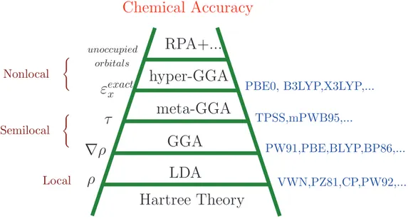
electrons gas, and proved to be extremely successful in practice. A useful way for categorizing the many and varied Exc[ρ] functionals that exist has been proposed by Perdew, known as Jacobs
ladder (Fig. 2.1) [54]. In this scheme functionals are grouped according to their complexity on rungs of a ladder which lead from the Hartree approximation on earth to the exact exchange-correlation functional in heaven. The most common types of exchange-exchange-correlation functionals in the field of solid-state physics, are the Local Density Approximation (LDA) and the Generalized-Gradient Approximation (GGA) located at the first few rungs of the ladder, which will thus be introduced in the following.
Hartree Theory
LDA
GGA
meta-GGA
hyper-GGA
RPA+...
ρ
∇ρ
τ
ε
exactx orbitals unoccupiedPBE0, B3LYP,X3LYP,...
TPSS,mPWB95,...
PW91,PBE,BLYP,BP86,...
Chemical Accuracy
VWN,PZ81,CP,PW92,...
(Local
Semilocal
Nonlocal
(Figure 2.1: Schematic diagram of “Jacobs ladder” of exchange-correlation functionals pro-posed by J. P. Perdew.
The Local Density Approximation At the center of the LDA is the idea of a hypothetical uniform electron gas, which describes a system of electrons in an infinite region of space with a uniform positive background charge to preserve overall charge neutrality. The electron density attains a constant everywhere. Physically, such a situation resembles the model of an idealized metal consisting of a perfect crystal of valence electrons and positive cores where the cores are smeared out to arrive at a uniform positive background charge. The uniform electron gas is the only system for which we know the form of the exchange and correlation energy functionals exactly or at least to very high accuracy. The idea to use this model for approximating Exc in
the Kohn-Sham scheme stems from the original paper by Kohn and Sham, in 1965 [53]. A real inhomogeneous system is divided into infinitesimal volumes where the local electron density is taken to be constant and the local exchange-correlation energy equals to the uniform electron gas for that density. Thus one can write the exchange-correlation energy under the form
ExcLDA=
Z
drρ(r)εxc[ρ(r)] (2.23)
with εxc[ρ(r)] being the exchange-correlation energy per particle of the homogeneous electron
![Figure 1.4: SEM images illustrating the impact of H on fracture in a hydride forming system (β Ti) [4]](https://thumb-eu.123doks.com/thumbv2/123doknet/3241584.92899/18.892.213.628.120.509/figure-sem-images-illustrating-impact-fracture-hydride-forming.webp)
![Figure 1.9: TEM image of the dislocation structure around a crack in fatigue in Fe-Si alloy in He atmosphere, from [9].](https://thumb-eu.123doks.com/thumbv2/123doknet/3241584.92899/22.892.198.640.493.812/figure-image-dislocation-structure-crack-fatigue-alloy-atmosphere.webp)
![Figure 1.10: TEM image of the dislocation structure around a crack in fatigue in Fe-Si alloy in H atmosphere, from [9].](https://thumb-eu.123doks.com/thumbv2/123doknet/3241584.92899/23.892.298.655.126.489/figure-image-dislocation-structure-crack-fatigue-alloy-atmosphere.webp)
![Figure 3.2: Thermal desorption spectrum of Ni after heat treatment at 950 o C, p H =3GPa for 2 h, from [11, 12].](https://thumb-eu.123doks.com/thumbv2/123doknet/3241584.92899/50.892.228.617.674.1005/figure-thermal-desorption-spectrum-ni-heat-treatment-gpa.webp)
![Figure 3.3: Lattice parameter changes over a whole run aimed at measuring the temporal variation at 896 o C and p(H 2 ) = 3 GPa[13].](https://thumb-eu.123doks.com/thumbv2/123doknet/3241584.92899/51.892.276.670.259.613/figure-lattice-parameter-changes-aimed-measuring-temporal-variation.webp)
![Figure 3.4: Magnitude of the lattice contraction measured at different temperatures and H pressures (left-hand scale).[13].](https://thumb-eu.123doks.com/thumbv2/123doknet/3241584.92899/52.892.226.616.146.445/figure-magnitude-lattice-contraction-measured-different-temperatures-pressures.webp)