HAL Id: tel-02071335
https://tel.archives-ouvertes.fr/tel-02071335
Submitted on 18 Mar 2019HAL is a multi-disciplinary open access archive for the deposit and dissemination of sci-entific research documents, whether they are pub-lished or not. The documents may come from teaching and research institutions in France or abroad, or from public or private research centers.
L’archive ouverte pluridisciplinaire HAL, est destinée au dépôt et à la diffusion de documents scientifiques de niveau recherche, publiés ou non, émanant des établissements d’enseignement et de recherche français ou étrangers, des laboratoires publics ou privés.
Heterogeneous catalysis in microreactors : study of the
performance of various supports
Xiaotong Zhan
To cite this version:
Xiaotong Zhan. Heterogeneous catalysis in microreactors : study of the performance of various supports. Chemical and Process Engineering. Ecole Centrale Marseille, 2018. English. �NNT : 2018ECDM0007�. �tel-02071335�
`
ÉCOLE CENTRALE DE MARSEILLE
École Doctorale – Sciences de l'environnement ED 251
Laboratoire de Mécanique, Modélisation et Procédés Propre (UMR7340)
THÈSE DE DOCTORAT
pour obtenir le grade de
DOCTEUR de l’ÉCOLE CENTRALE de MARSEILLE
Discipline : Génie des procédés
Heterogeneous catalysis in microreactors: study of the
performance of various supports
Par
ZHAN Xiaotong
Directrice de thèse :
Pr. DUPRAT Françoise
Co-directeur de thèse :
Dr. HÉRAULT Damien
Soutenue le 19 Octobre 2018
Jury
Dr. DUFAUD-NICCOLAI Véronique Université Claude Bernard Lyon 1 Rapporteur
Pr. COMMENGE Jean-Marc Université de Lorraine Rapporteur
Pr. GUICHARDON Pierrette École Centrale de Marseille Examinateur
Dr. FAVRE-REGUILLON Alain Conservatoire National des Arts et Métiers Examinateur
Pr. FOTIADU Frédéric École Centrale de Marseille Membre invité
Pr. DUPRAT Françoise École Centrale de Marseille Directrice de thèse
`
Acknowledgements
First of all, I would like to express my deepest gratitude towards my PhD supervisor Pr. Françoise DUPRAT for her enthusiastic and strong support to my PhD achievement, and Dr. Damien HÉRAULT for his kindness and his precise assistance all along this work. Although this thesis is interdisciplinary and its complexity is beyond expectation, thanks to Françoise and Damien, the emerged problems are well handled. They gave me great help not only in academic filed but also in general life. It is a really great privilege for me to work with them and I have realized how valuable these experiences in the three years will be during my entire life.
I am also grateful to the committee members: Dr. DUFAUD-NICCOLAI Véronique, Pr. COMMENGE Jean-Marc, Pr. GUICHARDON Pierrette and Dr. FAVRE-REGUILLON Alain, for providing their time in the examination and evaluation of my thesis.
I would like to thank persons who have contributed to my PhD works: M. PUJOL Didier for technical support, M. TREUVEY Arnaud for the help with UV analysis, Dr. CHEVALLIER-MICHAUD Sabine for the help with LC-MS measurements, Dr. NUEL Didier for the help with GC analysis, Dr. NICOLETTI Cendrine for teaching me the ultramicrotomy technology, Dr. CABIE Martiane for the help with TEM analysis and Dr. DOMINICI Chrisitian for the help with SEM analysis. I also thank the internship students TAGO Makoto, HORIOT Guillaume, GONÇALVES NETO João and LATTES Sophie for their contributions in the synthesis of monolith.
I would like to thank all my colleagues of Chiroscience group of ISM2 and TED group of M2P2. The interdisciplinary working atmosphere greatly helped my researches. I warmly thank Dr. Estelle GODART and HENNEBELLE Marc for their delicious cakes, Dr. Innocenzo DE RIGGI for the delicious croissants, and Augustin for the organization of football score contest and barbecue. I want to express my heartfelt gratitude to my parents and other family members. I cannot finish my PhD without their love, selfless support and encouragement.
I would like to thank all my friends, especially friends in Marseille, for their kindness help in my daily life. I also thank the association of Chinese students in Marseille, for providing the warmth of home and enriching my social experience.
Last but not least, I sincerely thank the China Scholarship Council (CSC) for the doctoral scholarship.
`
List of abbreviations
Chemical groups and moleculesAPTS (3-Aminopropyl)-triethoxysilane
ASM Aminopropyl silica monoliths
CPL ε-Caprolactam
DPTS 3-(2,4-Dinitrophenylamino)-propyltriethoxysilane
FA Formic acid
MCM Mobil Composition of Matter
MMA Methylmethacrylate
MPTS (3-Mercaptopropyl)- trimethoxysilane
MSM Mercaptopropyl silica monoliths
NSM Native silica monoliths
PAD 4,4'-Azodiphenol
PAP p-aminophenol
PAXD 4,4'-Azoxydiphenol
PBQI p-Benzoquinone imine
Pd Palladium
PDMS Polydimethylsiloxane
PEO Polyethylene oxide
Ph Phenyl PHB 4,4'-Azodiphenol PHx p-Hydroxylaminophenol PNP p-Nitrophenol PNS p-Nitrosophenol PPh3 Triphenylphosphine PP-PE Polypropylene-polyethylene PTFE Polytetrafluoroethylene
SBA Stanta barbara amorphous
TEOS Tetraethylorthosilane
THF Tetrahydrofuran
TTAB Tetradecyltrimethylammonium bromide
Instruments and analyses
BET Brunauer–Emmett–Teller
C.D. Condensation degree
CED Cumulative energy demand
CMR Chip microreactor
CP-MAS Cross polarization magic angle spinning
`
HPLC High performance liquid chromatography
LCA Life cycle assessment
LFR Low-flow reactor
MR Microreactor
MS Mass spectroscopy
NMR Nuclear magnetic resonance
PDA Photo-diode array
SEM Scanning electron microscopy
TEM Transmission electron microscope
UV Ultraviolet
Parameters
Ac cm2 Cross-sectional area of tube
Ce mmol/L Solution concentration
CFA mmol/L Concentration of formic acid
CFA0 mmol/L Initial concentration of formic acid
Ci mmol/L Molar concentration of component i in the liquid phase within the reactor
Ci° mmol/L Feeding concentration of component i in the liquid phase within the reactor
CPAPf mmol/L Concentrations of PAP at the exit of reactor
CPNP mmol/L Concentration of p-nitrophenol
CPNP0 mmol/L Initial concentration of p-nitrophenol
CPNPf mmol/L Concentrations of PNP at the exit of reactor
Dcat, PB mm Catalyst average diameter in packed-bed microreactor
DML mm Internal diameter of monolithic microreactor
DPB mm Internal diameter of packed-bed microreactor
E J Activation energy
Eapp J Apparent activation energy
ES- Negative electrospray ionisation in mass spectrometry ES+ Positive electrospray ionisation in mass spectrometry k (mol/L)1-n/min Reaction rate constant
K - Adsorption equilibrium constant
KD m2 Darcy permeability
LML mm Length of monolithic microreactor
LPB mm Length of packed-bed microreactor
m Stechiometric ratio (m = CFA0/3 CPNP0)
m/z Mass to charge ratio
mcat,ML mg Catalyst mass
mcat,PB mg Catalyst mass in packed-bed microreactor
mpd, PB mg Palladium mass in packed-bed microreactor
mpd,ML mg Palladium mass
n mol Mole of substance
` nPd mmol Moles of palladium in the reactor
Q mL/min Flow rate in microreactor
qI mmol/g Molar concentration of I component adsorbed on the catalyst surface
qT mmol/g Total concentration of catalyst sites
r mol/L/min Reaction rate of PNP per unit of catalyst volume
R1 Total aqueous phase volume/dodecane volume
R2 Mass of TTAB/mass of total aqueous phase
R3 Mass of TEOS/mass of total aqueous phase
R4 n(TEOS)/n(organosilane)
RF Response factor
s mmol/g Concentration of free catalyst sites
sc cm2 Adsorption cross section of the adsorbing species
Ss m2/g Specific surface areas of solids
T °C Temperature of reaction
tbatch min Time of reaction in batch reactor
TOF h-1 Turnover frequency
TON Turnover number
V mL Volume of solution
Va cm3/g Adsorbed gas quantity per unit of solid
Vbatch mL Total volume of the reactant
VCAT mL Total volume of catalyst
VLIQ mL Volume of the reaction mixture in batch reactor
Vm cm3/g Monolayer adsorbed gas quantity per unit of solid
VML mL Volume of tube of monolithic microreactor
VPB mL Volume of tube of packed-bed microreactor
X Conversion of p-nitrophenol
XSR Shrinkage ratio
p kPa Pressure drop
mPas Viscosity of liquid
ε Void fraction in the catalyst bed = VLIQ/(VLIQ+VCAT)
Others
RTD Residence time distribution
API Active pharmaceutical ingredients
cGMP Current good manufacturing practices
equiv. Equivalent
FU Functional unit
HIPE High internal phase emulsions
ID Internal diameter
`
Table of contents
Introduction ··· 1
Chapter 1 - Bibliographic study ··· 4
1.1 Microreactor with heterogeneous catalyst··· 4
1.1.1 Overview of microreactor ··· 4
1.1.2 Application of microreactors and industrial examples ··· 6
1.1.2.1 Contribution of microreactors to different types of reactions ··· 6
1.1.2.1.1 Fast and exothermic reactions ··· 6
1.1.2.1.2 Hazardous reactions ··· 9
1.1.2.1.3 Reactions with unstable intermediates or consecutive products ··· 11
1.1.2.2 Examples of industrial production with microreactor ··· 12
1.1.2.2.1 Scale-up methods ··· 12
1.1.2.2.2 Applications of microreactors in industrial productions ··· 15
1.1.3 Research status of microreactor with heterogeneous catalyst ··· 17
1.1.3.1 Different types and comparison of microreactors with heterogeneous catalysts ··· 18
1.1.3.1.1 Methods of immobilization of heterogeneous catalyst in microreactors ··· 18
1.1.3.1.2 Characteristic and comparison of different microreactors with heterogeneous catalysts ··· 19
1.1.3.2 Applications of microreactors with heterogeneous catalyst ··· 20
1.1.4 Conclusion ··· 22
1.2 Reduction of p-nitrophenol as model reaction ··· 23
1.2.1 Reduction of p-nitrophenol in heterogeneous conditions ··· 24
1.2.1.1 Methods of reduction··· 24
1.2.1.1.1 Reduction in neutral condition ··· 24
1.2.1.1.2 Reduction in alkaline condition ··· 25
1.2.1.1.3 Reduction in acidic condition ··· 28
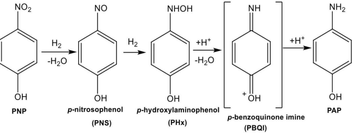
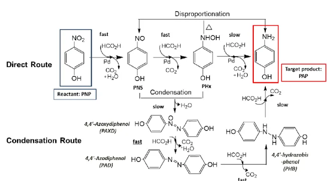
1.2.1.2 Mechanism of reduction in formic acid ··· 29
1.2.2 Methods of analysis ··· 32
1.2.3 Conclusion ··· 33
Chapter 2 - Study of p-nitrophenol hydrogenation as model reaction in a
packed-bed microreactor ··· 34
2.1 Experimental section··· 34
2.1.1 Experimental condition ··· 34
2.1.2 Protocol 1: off-line UV analysis ··· 35
2.1.2.1 Experimental set-up ··· 35
2.1.2.2 Off-line UV–vis spectroscopy Calibration··· 35
2.1.3 Protocol 2: on-line UV analysis ··· 37
2.1.3.1 Experimental set-up ··· 38
2.1.3.2 Washing protocols ··· 39
2.1.3.3 Analysis with off-line HPLC ··· 41
`
2.1.4.1 Experimental set-up with PDA and HPLC ··· 42
2.1.4.2 Analysis and washing protocols ··· 43
2.1.4.3 Calibration and corrections ··· 43
2.2 Reaction characterization ··· 45
2.2.1 Identification of products ··· 45
2.2.1.1 Analysis by nuclear magnetic resonance (NMR) ··· 45
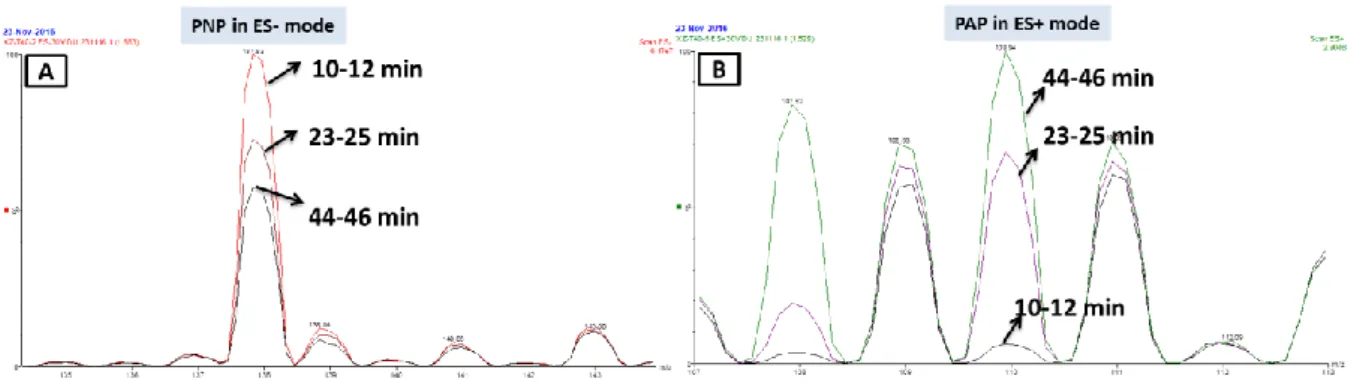
2.2.1.2 Analysis by mass spectrometry (MS) ··· 46
2.2.2 Comparison between batch and continuous conditions ··· 47
2.2.3 Study of adsorption and desorption phenomena ··· 49
2.2.3.1 Adsorption of PNP ··· 49
2.2.3.2 Adsorption and desorption of PAP ··· 51
2.3 Effect of reaction parameters on conversion ··· 53
2.3.1 Preliminary results ··· 53
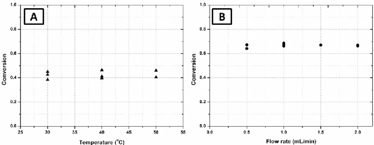
2.3.2 Influence of temperature and flow rate on the PNP conversion··· 54
2.3.3 Influence of the concentrations of reactants ··· 55
2.4 Dynamic studies ··· 56
2.4.1 Experimental observations ··· 56
2.4.1.1 Concentration profiles ··· 56
2.4.1.2 Effect of formic acid on intermediate ··· 58
2.4.2 Attempts for the identification of intermediate product··· 59
2.4.2.1 Test of possible intermediate according to plausible mechanism ··· 59
2.4.2.2 Evaluation of stability of intermediate ··· 62
2.5 Conclusion ··· 64
Chapter 3 - Modelisation of the reaction in packed-bed microreactor with
heterogeneous catalyst ··· 66
3.1 Ideal models of reactors and methods of calculation ··· 66
3.1.1 Steady-state plug flow model ··· 66
3.1.2 Ideal batch reactor model ··· 67
3.1.3 Unsteady-state catalytic plug flow model ··· 68
3.1.4 Resolution method of the unsteady-state catalytic plug flow model ··· 68
3.2 Simulation of reactor under transient conditions ··· 69
3.2.1 Reaction model with successive reactions ··· 70
3.2.1.1 Model hypothesis and resolution method ··· 70
3.2.1.2 Results of simulation ··· 71
3.2.2 Reaction model with change in the catalyst surface ··· 73
3.2.2.1 Model hypothesis and resolution method ··· 73
3.2.2.2 Results of simulation ··· 74
3. 3 Kinetic model of reaction under stationary conditions··· 75
3.3.1 Second order kinetics ··· 76
3.3.2 Comparison with possible mechanism of reaction ··· 79
`
Chapter 4 - Preparation and characterization of monolithic microreactor ··· 81
4.1 Monolithic catalyst ··· 81
4.1.1 Generality properties of monolithic materials ··· 81
4.1.2 Preparation of monolithic catalyst ··· 82
4.1.2.1 Organic polymer based monolithic catalyst ··· 82
4.1.2.2 Silica monoliths ··· 85
4.2 Experimental section··· 91
4.2.1 Preparation of functionalized monolithic catalyst ··· 91
4.2.1.1 Direct synthesis of functionalized monolith in polymer tube ··· 91
4.2.1.2 Growing of Pd nanoparticles within functionalized monolith in batch mode ··· 91
4.2.1.3 Direct synthesis of functionalized monolith in stainless-steel tube ··· 92
4.2.1.4 Continuous growing of Pd nanoparticles within functionalized monolith in stainless-steel tube ··· 92
4.2.2 Characterization method ··· 94
4.3 Characterization and discussion ··· 97
4.3.1 Optimization of preparation conditions of NSM, ASM and MSM in polymer tube ··· 97
4.3.1.1 Optimization of preparation conditions of NSM ··· 97
4.3.1.2 Optimization of preparation conditions of ASM ··· 99
4.3.1.3 Optimization of preparation conditions of MSM ··· 102
4.3.2 Characterization of the hierarchy of pores ··· 105
4.3.2.1 SEM and TEM analysis ··· 105
4.3.2.2 N2 Adsorption-desorption isotherm ··· 106
4.3.3 Characterization of Pd growing in batch mode within functionalized monolith ··· 108
4.3.4 Characterization of functionalized monolith prepared in the stainless-steel tube ··· 110
4.3.5 Characterization of Pd growing by continuous flow within functionalized monolith ··· 112
4.4 Conclusion ··· 114
Chapter 5 - Study of p-nitrophenol hydrogenation as model reaction in the
monolithic microreactor and comparison with packed-bed microreactor ··· 116
5.1 Experimental section··· 116
5.1.1 Experimental conditions ··· 116
5.1.2 Experimental set-up and protocol··· 116
5.1.3 Experimental condition range ··· 117
5.2 Effect of reaction parameters on conversion under stationary conditions ··· 117
5.2.1 Evaluation of catalyst stability··· 117
5.2.2 Influence of temperature and flow rate on the PNP conversion··· 118
5.2.3 Influence of concentrations of reactants on the PNP conversion ··· 119
5.3 Kinetic analysis of the reaction in the monolithic reactor ··· 119
5.4 Dynamic studies ··· 121
5.5 Comparison of packed-bed and monolith microreactors ··· 123
5.5.1 Catalyst performance in transfer hydrogenation reaction ··· 124
`
5.5.3 Difference in dynamic behavior and kinetic model ··· 126
5.6 Conclusion ··· 127
General conclusion and outlook··· 128
Introduction
Nowadays, the fine chemical and pharmaceutical industry must satisfy the demand of the increasing market requirements, meanwhile, respond specific needs of customer and social, such as environmental friendly production and energy savings. The microreactor technology, which has been proposed and investigated for two decades, which has a great potential for improving the current production mode: 50% of reactions in the fine chemical/pharmaceutical industry could benefit from a continuous process based mainly on microreactor technology.1
The role of catalysis in industry is irreplaceable. Over 90% of all industrial chemicals are produced in a catalytic process.2 Compared with homogeneous catalysis, heterogeneous catalyst, particularly solid catalyst, are widely used in industrial production because it can be separated in the process and recycled. Moreover, it can be implemented in fixed-bed reactor to improve the production efficiency.3 Hence, the combination of heterogeneous catalysis and continuous-flow microreactors has drawn attention recently.
Among different microreactors with heterogeneous catalysts, packed-bed microreactor is the most mentioned and investigated, because of its easy fabrication and high catalyst loading.4 It is commonly composed by a micro-channel randomly filled with powders or small pellets catalyst. The applications of microreactors with powder catalysts are largely limited in industry because the pressure drop could be significant and the possible catalyst aging could lead to the risk of clogging of microchannels. The monolithic microreactor is a rather new field and is currently in very rapid expansion in laboratory researches, due to its intrinsic advantages such as high porosity and large specific surface of catalyst support.5 However, the lack of effective preparation method of monolithic catalyst in industrial-grade reactor immensely limits its development. Thus, the key issue of this thesis resides in mastering the synthesis of monolithic microreactors, understanding the nature properties and differences between packed-bed and monolithic microreactor, and evaluating their industrial potentials.
Hence, the general objective of this study is to prepare the microreactors with mechanically stable monolithic catalyst. To prove the concept, the immobilization of a hybrid inorganic-organic monolithic will be realized in stainless-steel tube. Therefore, its performance will be compared to a packed-bed microreactor by a convenient model reaction.
This investigation is interdisciplinary: the chemical engineering contributes to the kinetic analysis and modelisation of the reaction tested in the
1
Roberge, D. M.; Ducry, L.; Bieler, N.; Cretton, P.; Zimmermann, B., Chemical Engineering & Technology 2005, 28 (3), 318-323.
2
Armor, J. N., Catalysis Today 2011, 163 (1), 3-9.
3
(a) Descorme, C.; Gallezot, P.; Geantet, C.; George, C., ChemCatChem 2012, 4 (12), 1897-1906. (b) Frost, C. G.; Mutton, L., Green Chemistry 2010, 12 (10), 1687-1703. (c) Sheldon, R. A.; Downing, R. S., Applied Catalysis A:
General 1999, 189 (2), 163-183.
4
Tanimu, A.; Jaenicke, S.; Alhooshani, K., Chemical Engineering Journal 2017, 327, 792-821.
5
microreactor, and the chemistry serves in the monolithic catalyst preparation and characterization. For this reason, the project has been supervised by two researchers, respectively of chemical engineering and chemistry, who can well handle the emerged problems from their respective fields. This work takes also into account the parallel studies of internship students who have been involved in the synthesis of monolith notably.
This thesis is divided in five chapters, and the organization is as follows:
The first one “Bibliographic study” gives an overview of the background knowledge of microreactors, emphasizing industrial applications and classification of reactions that take advantage of microreactor technology. The combination of heterogeneous catalysts with microreactors is discussed. Afterwards, the investigations on the reduction of p-nitrophenol in neutral, alkaline and acidic conditions are presented. The transfer hydrogenation of p-nitrophenol with formic acid is chosen as the model reaction of this thesis, because it seems a simple, clean and safe reaction, the reactive and product have important applications in chemical industry. The second chapter “Study of p-nitrophenol hydrogenation as model reaction in a packed-bed
microreactor” presents the investigations of model reaction catalyzed with a commercial
Pd@alumina powder. First of all, the set-up is developed, as well as an analytical method precise enough to get quantitative information about the concentrations of p-nitrophenol and
p-aminophenol, because published analytical methods didn’t work in our experimental
conditions. Then, the commercial catalyst is tested, and the effect of reaction parameters on conversion such as temperature, flow rate, initial concentration of reactants and time on flow are observed, with a special attention to the beginning of each run (dynamic study) and to their steady-state.
The third chapter “Modelisation of the reaction in packed-bed microreactor with
heterogeneous catalyst” describes the modeling investigations based on the experimental
observations in chapter 2. The ideal plug flow model is adopted to describe the packed-bed microreactor. The modelisation under transient conditions is firstly established for the rationalization of experimental observations, and then the model under stationary conditions is investigated to determine the reaction rate expression.
The fourth chapter “Preparation and characterization of monolithic microreactor” is dedicated to the preparation and characterization of the silica-based monolith with incorporated palladium nanoparticles. General research status about the preparation method of monolithic catalyst is firstly introduced, with the highlight of silica-based monolith. Then, series of silica-based monoliths have been prepared in cylinder PP-PE polymer tubes (syringe), for optimizing the preparation conditions of the stable, well-formed, hierarchically porous and functionalized silica monoliths. Thereafter, the functionalized silica monolith is prepared in a stainless-steel reactor tube with the optimized preparation conditions, and the palladium nanoparticles are immobilized by continuous flow method. A series of characterization methods are investigated to evaluate the monolith properties and confirm the effectiveness of preparation method.
The last chapter “Study of p-nitrophenol hydrogenation as model reaction in the monolithic
microreactor and comparison with packed-bed microreactor” includes the catalytic test of
monolithic catalyst with model reaction and the comparison of its properties with that of the commercial powder catalyst in packed-bed microreactor. The first experimental section presents the influence of reaction parameters such as temperature, flow rate and initial concentration of reactants on the conversion of p-nitrophenol in monolithic microreactor. Then the kinetic model of the reaction under stationary conditions is established, and the dynamic study of the reaction is presented. Finally, the performances of monolithic microreactor and packed-bed microreactor are compared, including their catalytic performances, the differences in dynamic study and kinetic model, and their pressure drop and permeability comparison.
Chapter 1 - Bibliographic study
This chapter concerns the background knowledge about heterogeneous catalyst in microreactor. At first, general introduction of microreactors and different types of microreactors with heterogeneous catalyst are presented; secondly, the model reaction chosen for catalytic tests: transfer hydrogenation of p-nitrophenol with formic acid is introduced, including the methods of the reduction and the mechanism of the reaction.
1.1 Microreactor with heterogeneous catalyst
1.1.1 Overview of microreactor
Over the past two decades, microfluidic technology has been advanced as means of process intensification6. Microreactor (MR) is currently burgeoning and is an interdisciplinary field that combines science and engineering7. The chemical industry8, biotechnology9, pharmaceutical industry10 and energy11 are just some of the fields where this new concept in production, analysis and research could find applications12.
A “microreactor” is a miniaturized reaction system with dimensions in the millimeter and submillimeter range, that is operated under flow conditions. Other names that are rarely used are nano-, mili- and mini-reactors.7(b) Most of the currently used microstructured devices take advantage of microfluidics and nanofluidics, which ensure high efficiency as well as repeatability of chemical processes13, due to high heat and mass transfer properties. More precisely, their thermal Peclet numbers14 are below 1,000 under operation and their Reynolds numbers are below 250, corresponding to laminar flow conditions.7(a)
The history of microfluidic devices dates back to 1940s when a millimeter scale electrophoretic separator has been studied by Philpot15. Then, in 1979, Terry16 realized a miniaturized gas chromatography apparatus on a silicon wafer, including fluid propulsion within microchannels of
6
Pohar, A.; Plazl, I., Chemical and Biochemical Engineering Quarterly 2009, 23 (4), 537-544.
7
(a) Elvira, K. S.; Casadevall i Solvas, X.; Wootton, R. C.; deMello, A. J., Nature Chemistry 2013, 5 (11), 905-15. (b) Šalić, A.; Tušek, A.; Zelić, B., Journal of Applied Biomedicine 2012, 10 (3), 137-153.
8
(a) Hessel, V.; Löb, P.; Löwe, H., Studies in Surface Science and Catalysis, Eds. Elsevier: 2006; pp 35-46. (b) Kralisch, D.; Kreisel, G., Chemical Engineering Science 2007, 62 (4), 1094-1100. (c) Al-Rifai, N.; Cao, E.; Dua, V.; Gavriilidis, A., Current Opinion in Chemical Engineering 2013, 2 (3), 338-345.
9
(a) Tu, S. T.; Yu, X.; Luan, W.; Löwe, H., Chemical Engineering Journal 2010, 163 (3), 165-179. (b) Cho, W.; Maeng, J. H.; Ahn, Y.; Hwang, S. Y., Eletrophoresis 2013, 34 (17), 2531-2537. (c) Lien, K. Y.; Lin, W. Y.; Lee Y. F.; Wang, C. H.; Lei, H. Y.; Lee, G. B., Journal of Microelectromechanical Systems 2008, 17 (2), 288-301.
10
(a) Nagaki, A.; Imai, K.; Kim, H.; Yoshida, J.-i., RSC Advances 2011, 1 (5), 758-760. (b) Yoshida, J.-i.; Kim, H.; Nagaki, A., ChemSusChem 2011, 4 (3), 331-340.
11
Kolb, G., Chemical Engineering and Processing: Process Intensification 2013, 65, 1-44.
12
Yao, X.; Zhang, Y.; Du, L.; Liu, J.; Yao, J., Renewable and Sustainable Energy Reviews 2015, 47, 519-539.
13
Urban, P. L.; Goodall, D. M.; Bruce, N. C., Biotechnology Advances 2006, 24 (1), 42-57.
14
Peclet number: a dimensionless number representing the ratio of heat transport by convection to heat transport by conduction, i.e. UρCP/λ, U:flow velocity, ρ:density, CP:specific heat capacity, λ:thermal conductivity 15
Philpot, J. S. L., Transactions of the Faraday Society 1940, 35, 38-46.
16
sub-millimeter cross section. The fabrication of the first high performance liquid chromatography (HPLC) device (a 5 x 5 mm chip containing an open-tubular column of 6 μm x 2μm x 15 cm) using Si-Pyrex technology published by Manz17 greatly boosts the development of microfluidic technology. The first micro-valves18 and micro-pumps19 based on silicon micro-machining have been studied and presented in the end of 1980s. Then in the 1990s, Manz20, Mathies21 and others have studied the microfluidic systems in the field of chip-based separations. Following these pioneer works, new microfluidic components were developed for fluid transport, fluid metering, fluid mixing, valving, or concentration and separation of molecules within miniaturized quantities of fluids22. Meanwhile, the research fields of continuous flow microreactors have been also well exploited in catalysis23, nanoparticle synthesis24, sensing25, electrochemistry26, polymerization27 among a lot of applications.
Microreactors are often compared with batch reactors. The characterization of the performances of reactors includes the conversion (for simple reaction), the yield (or selectivity) and the productivity. The ideal reactor models show that the performance equations, which reflect the effect of the operating conditions, are the same in a batch reactor and in a perfect plug flow reactor, which well represent microreactor. That is to say a reaction should follow identical reaction sequences, conversion rate and yield in an “ideal” microreactor and in an “ideal” batch reactor.
The implementation in real reactors brings out differences. Compared with conventional batch reactors, microreactors exhibit numerous advantages that have been discussed extensively.6-9 - Advantages of a flow-reaction: (1) in a batch reactor, the reactants are initially charged, and left to react for a certain period, then the final reaction mixture is discharged. So, under continuous operation, the productivity can be improved, by eliminating the steps related to loading and discharge; (2) the continuous operation can be automated more easily.
- Advantages related to the small dimensions of microreactors: (1) the reagent consumption is low, and changes in operating conditions are fast and easy to do, so microreactors are attractive during the process development phase; (2) the amount of reaction product is reduced, which is interesting in the case of synthesis of hazardous intermediate compounds.
17
A.Manz; Y.Miyahara; J.Miura; Y.Watanabe; H.Miyagi; K.Sato, Sensors and Actuators B: Chemical 1990, 1 (1-6), 249-255.
18
Shoji, S.; Esashi, M.; Matsuo, T., Sensors and Actuators 1988, 14 (2), 101-107.
19
(a) Lintel, H. T. G. V.; Vandepol, F. C. M.; Bouwstra, S., Sensor and Actuators 1988, 15 (2), 153-167. (b) V.Gass; Schoot, B. H. v. d.; S.Jeanneret; Rooij, N. F. d., Sensors and Actuators A: Physical 1994, 43 (1-3), 335-338.
20
Manz, A.; Graber, N.; Widmer, H. M., Sensors and Actuators B: Chemical 1990, 1 (1), 244-248.
21
Woolley, A. T.; Mathies, R. A., Proceedings of the National Academy of Sciences 1994, 91 (24), 11348-11352.
22
Haeberle, S.; Zengerle, R., Lab on a Chip 2007, 7 (9), 1094-110.
23
(a) Kobayashi, J.; Mori, Y.; Okamoto, K.; Akiyama, R.; Ueno, M.; Kitamori, T.; Kobayashi, S., Science 2004, 304 (5675), 1305-1308. (b) Kobayashi, S., Chemistry – An Asian Journal 2016, 11 (4), 425-436. (c) Rebrov, E. V.; Berenguer-Murcia, A.; Skelton, H. E.; Johnson, B. F. G.; Wheatley, A. E. H.; Schouten, J. C., Lab on a Chip 2009, 9 (4), 503-506.
24
Maki, T.; Kitada, J. I.; Mae, K., Chemical Engineering & Technology 2013, 36 (6), 1027-1032.
25
Wirnsberger, G.; Scott, B. J.; Stucky, G. D., Chemical Communications 2001, 0 (1), 119-120.
26
Watts, K.; Baker, A.; Wirth, T., Journal of Flow Chemistry 2014, 4 (1), 2-11.
27
Seo, M.; Nie, Z.; Xu, S.; Mok, M.; Lewis, P. C.; Graham, R.; Kumacheva, E., Langmuir 2005, 21 (25), 11614-11622.
- Advantages related to the geometry of microreactors, that offers great control of the reaction conditions such as concentrations and temperatures: (1) the control of temperature is obtained with the high surface area-to-volume ratio of microreactor, in the range of 10000 to 50000 m-1 in microreactor while it is usually less than 100 m-1 in traditional reactors28. This allows to use the full potential of temperature during highly exothermic reactions and avoids hot-spots formation29. According to their efficient heat transfer and small volume, the reactions involving reactive, toxic or explosive intermediates can be carried out in safety in microreactors6; (2) the control of concentrations in microreactors is achieved by an efficient micro-mixing and a short radial diffusion time, leading to a narrow residence time distribution (RTD) which give them a behavior close to the ideal plug flow model28. This behavior allows usage of minimal amounts of reagent to precisely control the reaction and provide high selectivity towards the desired product.7(b) The quality of mixing is especially important in the case of fast biphasic reactions or fast competitive reactions.
1.1.2 Application of microreactors and industrial examples
Although most of microreactors applications have been studied in academia, industry has also taken an inquisitive interest in this new technology. As proposed by Roberge, 50% of the reaction in pharmaceutical and fine chemical industry would benefit from a continuous process, and microreactor technology could be preferred reaction device in 44% of these reactions1. The question remaining is whether these microreactor devices are able to meet the expectations for industrial use raised in the academic environment. In the last fifteen years, a lot of companies, especially some microreactor builders such as BASF, Lonza, Corning, IMM, have studied microstructured devices as tools for process intensification, and they conclude that, not all chemical reactions can profit from microreactors. Hence, in the following part, the different types of reactions that take advantage in microreactors and some examples of industrial interest are presented.
1.1.2.1 Contribution of microreactors to different types of reactions
Among the great number of reactions carried out in microreactors in the lab or in the chemical industry30, three main types of reactions emerge clearly.
1.1.2.1.1 Fast and exothermic reactions
The batch reactors have many obvious advantages because they are easy to be handled, and also it is easy to visualize how a reaction proceeds, when a reagent or a catalyst is added into a flask or when heat is added to initiate a reaction. However, chemists usually slow-down organic
28
Kiwi-Minsker, L.; Renken, A., Catalysis Today 2005, 110 (1-2), 2-14.
29
Kolb, G.; Hessel, V., Chemical Engineering Journal 2004, 98 (1), 1-38.
30
(a) Kristal, J.; Stavarek, P.; Vajglova, Z.; Vondrackova, M.; Pavlorkova, J.; Jiricny, V., Research on Chemical
Intermediates 2015, 41 (12), 9357-9371. (b) McQuade, D. T.; Seeberger, P. H., Journal of Organic Chemistry 2013, 78 (13), 6384-6389. (c) Wiles, C.; Watts, P., Green Chemistry 2014, 16 (1), 55-62.
synthesis because it is very difficult or practically impossible to conduct some extremely fast or/and exothermic reactions in a flask due to the lack of control of the side reactions. The three following examples show how microreactors technology could contribute to the development of fast organic synthesis.
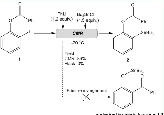
a- More than ten years ago a concept called “flash chemistry” was presented by Yoshida31. It is defined as a field of chemical synthesis where extremely fast reactions are conducted in a highly controlled manner to produce desired compounds with high selectivity. Among a number of studies conducted by Yoshida group on the potential of microreactors, an impressive example concerning the control of the fast organolithiums isomerization is presented here32. A chip microreactor (CMR), characterized by a submillisecond range reaction time even at cryogenic temperature has been designed. It allowed the formation of the desired product 2 from 1 with a 86% yield, without isomeric byproducts 3 (as shown in Figure 1) at a total flow rate of 4.5 mL/min corresponding to a residence time of 0.33 ms. The competitive very rapid anionic Fries rearrangement has been avoided, and a high chemoselectivity was observed. For a comparison, the reaction conducted in a conventional flask generated only the isomer 3. The rapid continuous flow nature of the CMR delivered a throughput of 5.3 g/hour, which show a great potential for scalable industrial chemical synthesis.
Figure 1 Reaction of unrearranged intermediates 1 to desired product 2 in CMR
31
(a) Yoshida, J. I.; Takahashi, Y.; Nagaki, A., Chemical Communications 2013, 49 (85), 9896-904. (b) Yoshida, J. I.,
Chemical Communications 2005, 0 (36), 4509-4516.
32
b- Wolf investigated the quite exothermic selective oxidation of primary alcohols to the aldehyde with oxygen using silver as the catalyst (Figure 2(A))33. The microreactor developed for this reaction is a cube of 1 cm edge length and having 200 crossed channels for the reactants and for the coolant (Figure 2(B)). Because of the efficient heat transfer, the reaction temperature could be controlled accurately, avoiding hot spots. Compared to traditional reactor consisting of thick catalyst layer placed on a gas-permeable plate, the reactor volume has been greatly reduced so that the residence time is largely decreased, and the selectivity could be increased from 40% and 85% to 96%, moreover, the hot spot has been reduced from 160℃ to 0℃.
Figure 2 Comparison of different reactors in the work of Wolf with the oxidative dehydrogenation
c- The two-step synthesis of m-anisaldehyde 5 from m-bromoanisole 4 as shown in Figure 3 is highly exothermic. Kralisch and Kreisel have studied this reaction in microreactor at both laboratory scale and industrial scale8(b). At the laboratory scale, the synthesis was conducted at 273K in a Cytos® microreactor with an internal volume of 1.1 mL with 88% yield, 28% higher than the yield obtained in a batch reactor. For the industrial scale, the numbering-up method has been chosen. The Cytos® Pilot System used was composed of 11 microreactors in parallel. The product mass flow of 0.06 kg/h per microreactor was the same on both scales. With same yield of 88%, the microreactor is at 273K while the reaction temperature of batch process should be held under 193K. Various indicators of life cycle assessment (LCA) showed that the application of microreactor could gain significant ecological advantages in comparison to the batch reactor, and the total CED (Cumulative Energy Demand) of microreactor is 500 GJ/FU (functional unit, 1 t m-anisaldehyde) lower than that of batch reactor.
33
Figure 3 Two-step synthesis of m-anisaldehyde 5 from m-bromoanisole 4
1.1.2.1.2 Hazardous reactions
The highly toxic or explosive nature of reactants or byproducts in some reactions can make it difficult to handle and control in a conventional lab or industrial scale. Indeed, the process involving hydrazine, diazo compounds, azides or cyanides can be problematic in the industrial production. However, the safe usage of these “dangerous materials” is recommended, especially if their applications offer better atom economy and process intensification. The reduction of risk and improvement of reactions have been demonstrated with the use of flow microreactor34. a- Hydrazine (N2H4) is a well-known powerful bi-functional nucleophile and a readily available
reducing agent. However, its utilization on a large scale has been limited because of the high toxicity and the high corrosiveness. The explosive and gaseous hydrazine in the batch reactor also makes the safety issues quite important35. For example, hydrazine is used in Wolff-Kishner reaction to reduce ketones and aldehydes to the corresponding alkane. The hydrazone intermediate could lead to formation of heterocycles such as insoles and azine by-products that should be discarded. In batch process, the reaction proceeds in the high temperature boiling solvent, in order to remove the hydrazone from the reactor. The method requires several hours of operation and a large excess of hydrazine. The microreactor could overcome these limitations, because its small volume and the improved mass and heat transfer reduce the risk of thermal runaway and explosions. Jensen35(a) has investigated the Wolff-Kishner reductions in a novel silicon carbide microreactor that prevents the hydrazine from boiling out of the reactor. Compared with typical batch conditions, the reaction time has been reduced by two orders of magnitude, and a high yield was obtained without requiring a large amount of hydrazine (Figure 4).
34
(a) Movsisyan, M.; Delbeke, E. I.; Berton, J. K.; Battilocchio, C.; Ley, S. V.; Stevens, C. V., Chemical Society
Reviews 2016, 45 (18), 4892-928. (b) Fanelli, F.; Parisi, G.; Degennaro, L.; Luisi, R., Beilstein Journal of Organic Chemistry 2017, 13, 520-542. (c) Gutmann, B.; Cantillo, D.; Kappe, C. O., Angewandte Chemie International Edition
2015, 54 (23), 6688-6728.
35
(a) Newman, S. G.; Gu, L.; Lesniak, C.; Victor, G.; Meschke, F.; Abahmane, L.; Jensen, K. F., Green Chemistry
2014, 16 (1), 176-180. (b) Wojewódka, A.; Bełzowski, J.; Wilk, Z.; Staś, J., Journal of Hazardous Materials 2009,
Figure 4 Comparison of batch and microreactor with the Wolff-Kishner reaction
b- Diazomethane (CH2N2) is one of the most versatile and powerful reagents available for the
preparation of carbon–carbon and carbon–heteroatom bonds in chemistry36. Nevertheless, diazomethane is an extremely volatile, poisonous, carcinogenic and explosive gas. Furthermore, it is extraordinary reactive and high sensitive to light, heat and mechanical shock34. The batch preparation of the diazomethane is always performed in specialized glass equipment without ground glass joints to avoid the light and shock. Purification and transportation of the diazomethane generated are also quite complicated37. Kim36 has investigated a dual-channel microreactor containing a highly hydrophobic poly (dimethylsiloxane) (PDMS) membrane that separated a channel for diazomethane generation and channel for synthesis. In the bottom channel, diazald® and KOH generate diazomethane, the PDMS membrane allow the transfer of diazomethane to the top channel while leaving water and other ionic salts behind. In the top channel, the gaseous diazomethane could react with various substrates with excellent yield (> 81%). Although the productivity in lab is only 0.58-2.88 mmol/day, this continuous in-situ generation, separation and reaction of high toxic reagents could be potentially useful for large-scale production.
Figure 5 Illustration of the microreactor (60 μL in volume with the 45 μm thick membrane) for in-situ generation, separation, and reactions of diazomethane36
36
Maurya, R. A.; Park, C. P.; Lee, J. H.; Kim, D. P., Angewandte Chemie International Edition 2011, 50 (26), 5952-5955.
37
1.1.2.1.3 Reactions with unstable intermediates or consecutive products
The reduction and elimination of short-lived intermediate and the consecutive product are always an important issue to deal with not only in laboratory but also in industrial production, in order to improve the productivity and purity of target product and to cut down the manufacturing cost. The continuous flow microreactor systems is an effective solution to this problem, which can greatly reduce the residence time to the order of milliseconds, keeping the flexibility of the addition order of reaction components. Moreover, the connection of different steps in microreactor could be much tighter in some reactions to reduce the undesired side or consecutive products, thereby to increase the purity of final product.
a- During the conversion from aryl and alkyl Grignard reagents to aryl and alkyl boron compounds, a number of elemental reactions give rise to side products which reduce the yield of the target product and generate purification problems. Hessel38 have investigated the replacement of a batch process by a continuous-flow process composed of a micromixer and a tubular reactor for the phenyl boronic acid 6 production. It results in notable process intensification: the best yield of microreactor investigations was 89%, about 24% more than the industrial batch-wise process. In addition, the energy expenditure was also reduced, due to operation at ambient temperature while the batch process was carried out at cryogenic temperatures. A pilot-scale configuration was achieved with a throughput of about 6kg of phenyl boronic acid per day, equivalent to a production of 20 tons of product per year. Last but not least, as intermediates may precipitate in the course of reaction, the results show that microreactors may adapt to fouling-sensitive reactions.
Figure 6 Main reaction of the Phenyl Boronic Acid Process and side/consecutive products (target poduct 6, side/consecutive products 7-12) and comparison of microreactor and batch
reactor in the Phenyl Boronic Acid 6 Process
38
Hessel, V.; Hofmann, C.; Löwe, H.; Meudt, A.; Scherer, S.; Schönfeld, F.; Werner, B., Organic Process Research &
b- ε-caprolactam(CPL) 16 is a commercially important chemical product, mainly used in the production of nylon 6 fibers and resins. Nevertheless, among the traditional methods of CPL synthesis, the CPL selectivity is usually lower than 90% in industrial process using consecutive continuous stirred tank reactors, on account of the several side products and the inefficient pre-mixing process. Wang39 has developed a system containing two consecutive microreactors and a stirred vessel to improve the selectivity of the synthesis of CPL. The first microreactor was used to conduct the reaction of cyclohexanecarboxylic acid
13 and oleum 14, and then the intermediate product named mixed anhydride was obtained
with 97% selectivity. The mixed anhydride then reacted quickly with nitroso-sulfuric acid 15 in the second microreactor, and then the reaction was finished in the vessel. The selectivity of CPL can reach 93.9%, much higher than that achieved in a batch reactor they investigated (84.6%).
Figure 7 Caprolactam 16 synthesis from cyclohexanecarboxylic acid 13
1.1.2.2 Examples of industrial production with microreactor 1.1.2.2.1 Scale-up methods
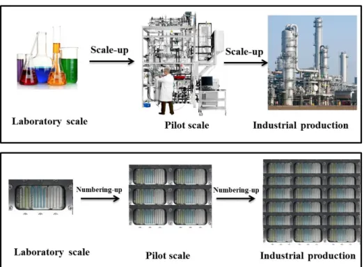
After the demonstration of the performance of microreactor in laboratory, the challenge is how to get benefits of microreactor in chemical industry while increasing the throughput for production. Two approaches to increase the production rate of microreactor are possible Figure 8 : scale-up by increasing the setup size and flow rates or numbering-up by parallelization of units.
39
Scale-up method can be more easily realized, while taking the risk of losing mass and heat transfer performance. Numbering-up could require hundreds of units to achieve the large-scale production and more complex and expensive control systems, but the desired features of a basic unit could be guaranteed40.
Figure 8 Simplified scheme illustrating scale-up versus numbering-up strategies
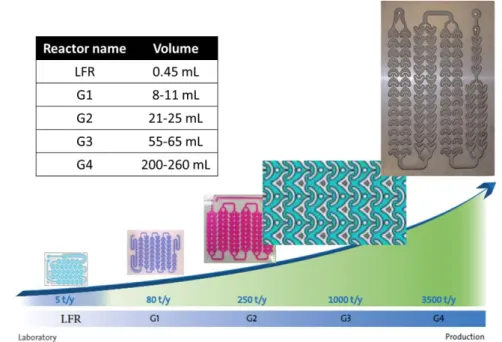
Within the context of microreactor scale-up, Corning combines the 2 approaches and offers several reactor volumes, following the same heart design. As shown in Figure 9, the Low-Flow reactor (LFR) has an internal volume of 0.45 mL, and has a throughput of 5t/year. The larger versions of reactor G1, G2, G3 and G4, have larger internal volumes and larger throughputs up to 2000t/year. In addition, Corning proposes the set-up with several parallel plates (Figure 10) to enlarge the productivity.
40
(a) Kockmann, N.; Gottsponer, M.; Zimmermann, B.; Roberge Dominique , M., Chemistry-A European Journal
2008, 14 (25), 7470-7477. (b) Ehrfeld, W.; Hessel, V.; Löwe, H., Microreactors: New Technology for Modern
Figure 9 The internal volume and throughput of Corning Advanced-Flow Reactors
Figure 10 Numbering-up set-up of Corning with several parallel plates
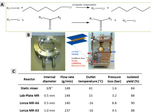
Lonza has also developed single-channel microreactors with different characteristics in terms of temperature control and production capacity, in view of scale-up from lab development to pilot-scale avoiding parallelization. The concept was exemplified with the fast and highly exothermic lithiation reaction (Li–H exchange and coupling, shown in Figure 11 (A))41. The first reaction has an adiabatic temperature rise of more than 75℃, and feeds were precooled to the cryogenic reactor temperature. Two types of Lonza microreactors, a Lab-Plate and modular plate A6 or A5, shown in Figure 11 (B), were compared with a classic static mixer. The results are summarized in Figure 11 (C).
41
Figure 11 Research of lithiation reaction with Lonza microreactor. (A) Reaction scheme of Li–H exchange and coupling; (B) Different Lonza microreactors (left: Lab-Plate 0.4-3 mL, Right: plate A6 (3-12 mL) or A5 (7-33 mL)); (C) Comparison of different reactors and flow rates for scale-up
of the lithiation reaction
The results with the Lab-plate show a loss of temperature control, but not yet reflected in the product yield, while the largest reactor (Lonza MR-A5), could achieve a throughput over 200 g/min by keeping the pressure drop well under control. 700 kg of isolated material were produced in a pilot campaign, showing the long-term robustness of the process and reliability of the installed reactor equipment.41
1.1.2.2.2 Applications of microreactors in industrial productions
Industry is not very active in publishing not only because of confidentiality reasons. This may also be caused by the fact that many aspects of this new technology were covered by patents42. Scarce publications are probably the tip of the iceberg, and as several of the earlier patents have now expired, known examples of applications of microreactors in industrial productions will increase.
Initiated in 2005 in Germany, the DEMiS projet (Degussa, Uhde, TU Chemnitz, TU Darmstadt, MPI Mulheim) is the first and most often mentioned example for microreactor industrial process up to now 43. A microstructured reactor has been used for the epoxidation of propylene to propylene oxide with H2O2 on a TS-1 zeolite. The production capacity of this process approximates 5-10
t/year.
42
(a) Hessel, V.; Knobloch, C.; Löwe, H., Recent Patents on Chemical Engineering 2008, 1(1), 1-16. (b) Dencic, I.; Hessel, V.; de Croon, M. H.; Meuldijk, J.; van der Doelen, C. W.; Koch, K., ChemSusChem 2012, 5 (2), 232-45.
43
Reschetilowski, W., Microreactors in Preparative Chemistry, Wiley-VCH Verlag GmbH & Co. KGaA: 2013; pp 1-12.
A nitroglycerin pilot plant with the productivity 10kg/h has been installed at Xi'an site in China and has started up in 2005 with the collaboration from Germany’s Institute for microtechnology Mainz (IMM)44. Microreactor technology is the key to this production process and the plant is foreseen to operate safely and fully automated 8.
Figure 12 Nitroglycerin microstructured reactor based pilot plant (Xi’an/ China)
An industrial scale plant for the free radical polymerisation of methylmethacrylate (MMA) was designed by Iwasaki and Yoshida. This pilot plant was installed in Japan, at the Idemitsu Company and its capacity of production is 10t/year 8. Eight micro-reactor blocks are arranged in a parallel manner. Each of these blocks contains three micro-tube reactors of 11.8 mL (500 μm internal diameter, 60 cm length) in series.
Figure 13 Industrial pilot plant (10 t/year ) with three micro-reactor blocks for radical polymerisation in Japan 8
It should be noticed that the performance of this pilot plant was similar to that of a single micro-reactor tube, which demonstrates that external numbering-up of microreactors is able to be successfully applied to industrial production.
44
Another impressive industrial production with microreactor is the process development for pharmaceutical production under cGMP (current Good Manufacturing Practices) conditions, developed by DSM, a manufacturer of fine chemicals and active pharmaceutical ingredients, and Corning Inc.45. The goal of this project was to develop a safe and highly selective nitration process using pure nitric acid, and get the desired amount and quality of product at full GMP level. A commercially viable approach to a cGMP nitration reaction was investigated with individual reactor modules, then the numbering-up concept was applied. After nine months, the production process had a capacity of approximately 100 kg/h which corresponds to nearly 800 tons per year.
Figure 14 Production bank with four identical reactors and distribution 45
1.1.3 Research status of microreactor with heterogeneous catalyst
The role of catalysis in industry is irreplaceable. Over 90% of all industrial chemicals are produced in a catalytic process 2. Both homogeneous and heterogeneous catalysis find wide application in chemicals production. Compared with homogeneous catalysis, heterogeneous catalysts, especially the solid catalysts, gain more attention in the industrial production because they are easily separated in the process, and they can be implemented in fixed-bed reactor to improve the production efficiency3. In addition, they are cheap, easy to get, and have good thermal stability. However, heterogeneous catalysts are difficult to implement in microreactor. So, this combination has drawn attention only recently. The potential advantages of the microreactor with heterogeneous catalysts have been discussed in some recent reviews 3-5,46: ultra-low catalyst consumption, more efficient use of resources and generation of less waste, high specific surface areas of catalysis and so on. In the following part, we present different types of microreactors with heterogeneous catalyst and their applications.
45
Braune, S.; Pöchlauer, P.; Reintjens, R.; Steinhofer, S.; Winter, M.; Lobet, O.; Guidat, R.; Woehl, P.; Guermeur, C.,
Chemistry Today 2009, 27 (1), 26-29.
46
(a) Yue, J., Catalysis Today 2017. (b) Munirathinam, R.; Huskens, J.; Verboom, W., Advanced Synthesis &
1.1.3.1 Different types and comparison of microreactors with heterogeneous catalysts 1.1.3.1.1 Methods of immobilization of heterogeneous catalyst in microreactors
Heterogeneous catalytic microreactors can be classified into three main types as shown in Figure 15: (i) packed-bed microreactor, (ii) wall-coated microreactor and (iii) monolithic microreactor.
Figure 15 Schematic representation of the cross-section of a microchannel in (a) packed-bed, (b) wall-coated, and (c) monolithic microreactors 46(b)
Packed-bed microreactor is among the most studied, commonly composed by a micro-channel randomly filled with powders or small pellets catalyst. The support of the catalyst is an insoluble solid, either a polymeric or inorganic particle. The particles are generally smaller than 50μm, less than 1/20 of the bed diameter to avoid the channeling or misdistribution of flow 4. Catalyst can be loaded into the microchannel either by manual filling, or by applying a pump or vacuum at the reactor outlet. Besides, the packed catalyst should be retained inside the microchannel by sinters at both ends. The possibility to use either commercial or synthesized bulk catalysts greatly expands the application areas 46(a).
Wall-coated microreactor has inner wall with a uniform and thin layer thickness (usually in the 1– 10 μm range) of catalytic coating. Several reviews 5,46-47 have discussed the methods of the immobilization of catalytic wall coatings into capillary- or chip-based microreactors, such as the sol-gel deposition48, electrophoretic deposition49 and electroless plating, chemical vapor
47
Meille, V., Applied Catalysis A: General 2006, 315, 1-17.
48
Peneau, V.; Shaw, G.; Freakley, S. J.; Forde, M. M.; Dimitratos, N.; Jenkins, R. L.; Taylor, S. H.; Hutchings, G. J.,
Catalysis Science & Technology 2015, 5 (8), 3953-3959.
49
Wunsch, R.; Fichtner, M.; Görke, O.; Haas‐Santo, K.; Schubert, K., Chemical Engineering & Technology 2002,
deposition technique50. The general steps of the immobilization often involves 46: i) pre-treatment of the microreactor wall surface; ii) application of a porous coating of the catalyst support; iii) immobilization of the catalyst itself (usually noble metal like Pt, Pd or Au) onto the catalyst support.
Monolithic microreactor is a microreactor in the form of column with monolith inside. Monolith is the solid material polymeric51 or inorganic52, structured with interconnected pores that are both macropores (larger than 50nm in diameter) and mesopores (2-50nm) or micropores (less than 2nm)53. Different from the mature packed-bed technology, monolithic microreactor is a rather new field, which is currently in very rapid expansion, due to the huge interest and spread in organic flow synthesis5.
1.1.3.1.2 Characteristic and comparison of different microreactors with heterogeneous catalysts
The relative advantages and disadvantages of heterogeneous catalytic microreactors have been discussed in several publications 4,46,54.
Generally speaking, packed-bed microreactors can be made easily because the catalysts can be directly introduced into the microreactors after suitable size reduction. This approach gives access to a large range of catalytic supports. Advantages of such packed-bed are high catalyst loading and fairly easy characterization and quantification of the catalyst. However, limitations can be the poorly controlled fluid dynamics and the significant pressure drops along the microchannel. In addition, the presence of solid catalyst may limit heat transfer and lead to hot-spot formation.
Unlike packed-bed microreactors, the mass transfer resistance is minimized in wall-coated microreactors to ensure smooth flow of reagents, without leading significant pressure drops or blockage of microchannels. Moreover, the fluid dynamics, the heat and mass transfer properties inside the wall-coated microreactors can be well predicted due to the well-defined flow geometries. Despite of the good flow-through properties, the major disadvantage is the low catalyst loading, owing to the thin layer of catalyst supported on the inner walls.
Monolithic catalysts are designed to have quite high void volume and a large specific surface area, leading to efficient contact of the catalyst, allowing high productivity and selectivity. The drawbacks of monolithic microreactors could be the compromise between the pressure drop and the flow rate, the preparation of the catalyst inside the microreactor channels, leading to difficulty of modelization and the risk of pore clogging or non-uniformity of radial permeability 5.
50
Janicke, M. T.; Kestenbaum, H.; Hagendorf, U.; Schüth, F.; Fichtner, M.; Schubert, K., Journal of Catalysis 2000,
191 (2), 282-293.
51
Viklund, C.; Svec, F.; Fréchet, J. M. J.; Irgum, K., Chemistry of Materials 1996, 8 (3), 744-750.
52
Walsh, Z.; Paull, B.; Macka, M., Analytica Chimica Acta 2012, 750, 28-47.
53
According to IUPAC definition
54
(a) Sachse, A.; Galarneau, A.; Coq, B.; Fajula, F., New Journal of Chemistry 2011, 35 (2), 259-264. (b) Kirschning, A.; Solodenko, W.; Mennecke, K., Chemistry-A European Journal 2006, 12 (23), 5972-5990.
1.1.3.2 Applications of microreactors with heterogeneous catalyst
In the recent review by Alhooshani 4, applications of heterogeneous catalytic microreactors have been discussed. We present some examples of applications of microreactors with heterogeneous catalyst with impressive performance in pharmacy.
The pharmaceutical industry is going through a change from batch systems to continuous-flow systems. During each stage of the development of a drug, the quantities of active compound required increase: for the initial tests during discovery, only 5-10 mg is required; for the toxicology and pharmacokinetics studies, 500 mg-2 g are required; finally, kilogram-amounts are required for larger trials. The microreactors with heterogeneous catalyst are easily compatible with the aim of small amounts production. In addition, with the scale-up or numbering-up method, they have great potential in the pharmaceutical production.
Recently, applications of continuous flow processes in pharmaceutical industry such as the preparation of fine chemicals, active pharmaceutical ingredients (API) and finished dosage forms have been gained much attention, especially in academia 55.
a- Recently, the Novartis/MIT partnership demonstrates an excellent example of industry/academic collaboration in a fully automated integrated continuous flow synthesis apparatus55(e)(f),56. The instrument is not bigger than a kitchen refrigerator (as shown in Figure 16) and can be easily adapted to produce a variety of target molecules meeting U.S. pharmacopeia standards, for example the Aliskiren (drug for hypertension) with a productivity of 41g/h.
55
(a) Baumann, M.; Baxendale, I. R., Beilstein Journal of Organic Chemistry 2015, 11, 1194-219. (b) Porta, R.; Benaglia, M.; Puglisi, A., Organic Process Research & Development 2015, 20 (1), 2-25. (c) Battilocchio, C.; Deadman, B. J.; Nikbin, N.; Kitching, M. O.; Baxendale, I. R.; Ley, S. V., Chemistry 2013, 19 (24), 7917-7930. (d) Malet-Sanz, L.; Susanne, F., Journal of Medicinal Chemistry 2012, 55 (9), 4062-4098. (e) Mascia, S.; Heider, P. L.; Zhang, H.; Lakerveld, R.; Benyahia, B.; Barton, P. I.; Braatz, R. D.; Cooney, C. L.; Evans, J. M.; Jamison, T. F.; Jensen, K. F.; Myerson, A. S.; Trout, B. L., Angewandte Chemie International Edition 2013, 52 (47), 12359-12363. (f) Adamo, A.; Beingessner, R. L.; Behnam, M.; Chen, J.; Jamison, T. F.; Jensen, K. F.; Monbaliu, J.-C. M.; Myerson, A. S.; Revalor, E. M.; Snead, D. R.; Stelzer, T.; Weeranoppanant, N.; Wong, S. Y.; Zhang, P., Science 2016, 352 (6281), 61-67. (g) Tsubogo, T.; Oyamada, H.; Kobayashi, S., Nature 2015, 520 (7547), 329-332. (h) Poechlauer, P.; Manley, J.; Broxterman, R.; Gregertsen, B.; Ridemark, M., Organic Process Research & Development 2012, 16 (10), 1586-1590. (i) Cole, K. P.; Johnson, M. D., Expert Review Clinical Pharmacology 2018, 11 (1), 5-13. (j) Hawkins, J. M., Nature
2015, 520, 302-303.
56
Heider, P. L.; Born, S. C.; Basak, S.; Benyahia, B.; Lakerveld, R.; Zhang, H.; Hogan, R.; Buchbinder, L.; Wolfe, A.; Mascia, S.; Evans, J. M. B.; Jamison, T. F.; Jensen, K. F., Organic Process Research & Development 2014, 18 (3), 402-409.
Figure 16 Reconfigurable system for continuous production and formulation of APIs developed by a Novartis/MIT group 55(f) (a: Labeled photograph of the stack of upstream synthesis modules;
b: Labeled photograph of the downstream purification and formulation modules.)
The continuous-flow system contains four types of microreactors, types I and II without catalyst, types III and IV with catalyst, as illustrated in Figure 17. In type I, all the reagents are passed through the reactor, and the exiting mixture contains target products with the unreacted reagents or by-products and a further separation step is necessary. In type II, one of the reagents, saying B, is supported and confined into the reactor. If an excess amount of supported B is used, the exiting reaction mixture will contain the target product only. However, the reactor must be changed frequently due to the consumption of B. In type III, a homogeneous catalyst is employed; similar to type I, the further separation step is necessary. In type IV, the heterogeneous catalyst is immobilized into the reactor, so the catalyst can be reused easily. According to authors, this type of reactor is regarded as the most convenient for continuous-flow synthesis because the catalytic methodologies are nowadays imperative for the development of sustainable and efficient processes55(b)(g).
Figure 17 Four types of continuous-flow microreactors
b- An impressive, complete and chiroselective synthesis of an API, (R)-Rolipram 18, using heterogeneous catalytic continuous-flow system has been described by Kobayashi 55(g)(j). The starting materials and related reagents have been passed through a sequence of chiral and achiral solid catalysts as shown in Figure 18. Moreover, the (S)-Rolipram 19 was obtained simply by replacing the chiral heterogeneous catalyst in reactor II with the opposite enantiomer catalyst. The yield is 50% from commercially available aldehyde 17, the productivity is 1g per 24 h and the enantiomeric excess is 96% for both of the products 18 and 19.
Figure 18 Flow synthesis of the anti-inflammatory drug (R)-Rolipram and (S)-Rolipram with four reactors (D: 5-10mm, L: 50-300 mm) packed with solid catalysts
1.1.4 Conclusion
The overview of microreactors and their advantages related to continuous operation, small dimension and geometry have been introduced. Microreactors have been applied in different types of reactions, in order to control the reaction rate, reduce the release the highly toxic products and reduce the side-products. Compared to related traditional batch processes, the