Publisher’s version / Version de l'éditeur:
Vous avez des questions? Nous pouvons vous aider. Pour communiquer directement avec un auteur, consultez la première page de la revue dans laquelle son article a été publié afin de trouver ses coordonnées. Si vous n’arrivez pas à les repérer, communiquez avec nous à PublicationsArchive-ArchivesPublications@nrc-cnrc.gc.ca.
Questions? Contact the NRC Publications Archive team at
PublicationsArchive-ArchivesPublications@nrc-cnrc.gc.ca. If you wish to email the authors directly, please see the first page of the publication for their contact information.
https://publications-cnrc.canada.ca/fra/droits
L’accès à ce site Web et l’utilisation de son contenu sont assujettis aux conditions présentées dans le site LISEZ CES CONDITIONS ATTENTIVEMENT AVANT D’UTILISER CE SITE WEB.
Cold Regions Science and Technology, 11, 3, pp. 247-253, 1985-11
READ THESE TERMS AND CONDITIONS CAREFULLY BEFORE USING THIS WEBSITE.
https://nrc-publications.canada.ca/eng/copyright
NRC Publications Archive Record / Notice des Archives des publications du CNRC :
https://nrc-publications.canada.ca/eng/view/object/?id=25b15ece-3463-41cf-841a-892d1cc32cdf
https://publications-cnrc.canada.ca/fra/voir/objet/?id=25b15ece-3463-41cf-841a-892d1cc32cdf
NRC Publications Archive
Archives des publications du CNRC
This publication could be one of several versions: author’s original, accepted manuscript or the publisher’s version. / La version de cette publication peut être l’une des suivantes : la version prépublication de l’auteur, la version acceptée du manuscrit ou la version de l’éditeur.
Access and use of this website and the material on it are subject to the Terms and Conditions set forth at
Stress-relieving techniques for cantilever beam tests in an ice cover
Frederking, R. M. W.; Svec, O. J.
Sor
TIU
Iiq77g
N21d
Natlonal Research Consell natlonalnu. 1343
I*
Council Canadack
rechehes Canadac.
2
Division of Division desBLDG
Building Research recherches en Mtiment --Stress-Relieving Techniques for Cantilever
Beam Tests in an Ice Cover
by R.M.W. Frederking and O.J. Svec
Reprinted from
Cold Regions Science and Technology Volume 11, 1985, p. 247
-
253 (DBR Paper No. 1343) P * - ' ' r --7
Price $2.00 NRCC 25263 .LNe.
ZKJ
I
L I I R A I Y
86-
n ? - ?
i
B ~ B L I O T H ~ Q U E
1
- 'Rlch.
--W i m .
l C l S T,
DBRIDRB
Canad3
6170r
37
Des essais de poutre en console effectu6s sur une couverture de
glace d'eau douce ont montr6 que le fait de relgcher les
contraintes en forant des trous pres de l'encastrement de la
poutre augmentait la r6sistance en flexion d6terminge par la
th6orie des poutres simples dans une proportion de
1/4 3 1 / 3 .
L'analyse
par la m6thode des 616ments finis a confirm6
l'existence d'une concentration des contraintes au bord de la
poutre, lesquelles sont 1,5 plus fortes qu'au centre en
pr6sence de trous et
2 fois plus fortes en l'absence de trous.
On peut d6terminer la
resistance
en flexion des poutres en
consoles en appliquant un facteur de correction de 1,08 lorsque
des trous ont 6t6 pratiqugs prss de l'encastrement et de 1,35
dans le cas contraire.
Cold Regions Science and Technology, 11 (1985) 247-253
Elsevier Science Publishers B.V., Amsterdam - Printed in The Netherlands
STRESS-RELIEVING TECHNIQUES FOR CANTILEVER BEAM TESTS
IN
A N ICE COVERR.M.W. Frederking and O.J. Svec
Division of Building Research, National Research Council o f Canada, Ottawa, Ontario (Canada)
(Received February 22, 1985; accepted in revised form May 1,1985)
ABSTRACT
Cantilever beam tests carried out on a freshwater ice cover showed that introducing stress relief holes at the root of the beam increased flexural strength, as determined from simple beam theory, by 114 to 113, compared to conventional cantilever beams. Finite element analysis confirmed the existence o f stress concentrations at the edge of the beam, 1.5 times the centre stress for the case of a stress relief hole and 2 times in the case of a cantilever beam without stress relief holes. A correction factor of 1.08 has been determined for the flexural strength o f cantilever beams with stress relief holes at the root; for those with no special root treatment, the correc- tion factor is 1.35.
INTRODUCTION
The flexural behaviour of ice is important for the prediction of bearing capacity of ice covers and ice loading on structures. It is also a significant factor in natural ice failure processes such as ridge building, ride-uI;, pile-up and rubble building. Usually the flexural properties of an ice cover are determined from in situ cantilever beam tests. The interpreta- tion of the results of such tests is critical for their subsequent application to other cases of flexural behaviour. Flexural testing has the drawback of being an indirect test, i.e., certain assumptions have to be made about material and beam behaviour in order to interpret the results. On the other hand, the test is an analogue of the loading condition which it models.
The cantilever beam test is often used for in situ flexure tests on ice covers in the field and in model basins (Frankenstein, 1970; Schwarz, 1975; Vaudrey, 1978). The results of such tests are normally analyzed in terms of simple beam theory, assuming the can- tilever is rigidly clamped at the root and ignoring any stress concentration at that location. These shortcomings have been recognized and various analytical and experimental techniques proposed to compensate for them. Maattanen (1975) studied beam and root geometry effects during field tests carried out in the Baltic, and found a decrease in strength and modulus with increasing ratio of beam width to ice thickness. Beam lengths up t o ten times ice thickness had no effect on flexural strength, but modulus decreased with decreasing length. Beams with a large radius of curvature at the root had strengths about 30% greater than ones terminating with straight saw cuts at the root. Gow (1977) carried out an extensive series of in situ tests on both cantilever and simply supported beams. He found that the flexural strength of simple beams was as much as twice the strength of corresponding can- tilever beams. The difference was attributed to the effect of stress concentration. When Svec and Freder- king (1981) examined the influence of geometry at the root of a cantilever beam, we found moments
in the root area to be 50% greater than those deter- mined from simple beam theory.
To address more fully this problem of performing and interpreting the results of cantilever beam tests, parallel investigations were implemented using photo- elasticity, finite element analysis and full-scale field tests. This paper presents the results of in situ beam tests in a natural ice cover where special measures
were taken to reduce the stress concentrations at the root of the beam. These results are compared with predictions of a finite element analysis.
FIELD TESTS
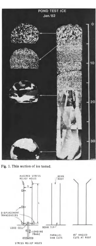
Field tests were carried out in late January and early February 1982 on the ice cover of an out- door manoeuvering basin (60 X 120 m) at the Na- tional Research Council in Ottawa. At that time the ice thickness was 0.35 m, snow depth 0.2 m and freeboard 0.005 m. The ice, as shown in Fig. 1, was made up of a 170 mm thick top part of snow ice (Type T1) (see Michel and Ramseier, 1971) with a grain diameter of 0.5 to 5 mm, and a remaining 180 mm of columnar grain ice with very large grain diameters. Care was taken to select a site with horlo- geneous ice conditions and without visible cracks. Air temperature during the tests was in the range -5 to -20°c, so there was a temperature gradient through the ice cover. Environmental conditions for the tests are given in Table 1.
The beams were cut out with a chain saw. Initial cuts were made through about 314 of the ice thick- ness, thus keeping the cut dry. The final part of the cut was done with a ha'ndsaw to minimize the amount of surface flooding. Stress relief holes were drilled at the root with ice augers of various diameters. In order not to change the original loading and tem- perature conditions, the snow cover was left un- disturbed on the ice except along the cutting paths. Nevertheless there was a warming of the ice during beam preparation and testing, due mainly to the presence of O'C water in the saw cut and stress relief holes. Also there was sufficient snowfall be- tween Tests 5 and 6 to depress the ice, causing a negative freeboard of 40 mm.
Following the guidance of photoelastic model studies, stress relief holes were drilled at the root of the beam tangent to the side cuts. A variety of treatments at the beam root were used, including parallel saw cuts, 25, 100, 150 and 250 mm diameter holes, and 45" angled cuts (see Fig. 2). Load was applied to the tip of the beam by a hydraulic cylinder reacting against a loading frame anchored to the ice cover. Load was measured by a load cell between the cylinder and the ice beam. Three displacement
Fig. 1. Thin section of ice tested.
A U G E R E D S T R E S S R E L I E F H O L E S
(%
I
BEAM T I P N G P A R A L L E L S A W C U T S1'
4 5 " A N G L E D C U T S A T R O O T S T R E S S R E L I E F H O L E SFig. 2. Schematic of test arrangements for different beam
transducers were used to measure deflections of the beam. Continuous records of load and deflections versus time were made. A typical record is shown in Fig. 3 (Test 1). Because a hand pump was used to pressurize the cylinder, a step-wise loading resulted. A load relaxation between strokes of the hand pump
is apparent. Load was always applied downwards *
6 1
so that the top fibres of the beam were in tension. The load versus deflection results for Test 1, plotted
5
in Fig. 4, show that the load/deflection curve is relatively linear; serrations in the curve are due to the load relaxation mentioned above.T I M E , s
D E F L E C T I O N , rnm
Fig. 4. Load ( P ) versus deflection at tip (6 ,) and at mid-point of beam ( 6 ,), Test No. 1.
TEST RESULTS
The results of all the tests are summarized in
Table 2. Flexural strength (asb) and elastic modulus (Esb) were calculated from simple elastic beam theory using the following equations
6P'L
Fig. 3. Load ( P ) and deflection at tip (6,) and mid-point of osb =
-
beam (6 ,) versus time, Test No. 1. bh2TABLE 1
Environmental conditions during cantilever-beam tests
Test Date Air temp. Ice surface temp. Sky Notes
" C before after
1 Jan. 27 pm -15 -4 -0.5 clear 2 Jan. 28 pm -10 -2 0.0 snow
flurries
3 Jan. 28 pm -8 -0.1 -0.2 snow Slush between snow flurries cover and ice surface 4 Jan. 29 am -10 -0.1 -0.1 clear
5 Jan. 29 pm -8 -0.2 0.0 clear
6 Feb. 01 -8 -1.9 0.0 clear Snowed overnight, snow depth 37 cm, 4 cm of water on ice surface
250
TABLE 2
Geometry of beams and test results
Test No. Root P' L b h usb If PI6 Esb
(kN) (m) (m) (m) (kPa) (s) (MNIm) (GPa)
1 saw cuts 2.05 2.41 0.40 0.35 610 25.0 1.44 4.7 2 15 cm 4 2.55 2.34 0.405 0.35 720 13.7 1.51 4.4 3 2.5 cm
+
1.85 2.42 0.415 0.35 530 7.3 1.40 4.5 4 45" angle 2.80 2.12 0.465 0.34 660 8.5 - - 5 25 cm (B 2.10 2.34 0.38 0.34 680 6.9 --
6 10 cm $ 2.65 2.45 0.405 0.35 780 6.0 - - 7 saw cuts 1.55 2.35 0.39 0.35 460 6.3 1.77 5.4where
P'
is breaking load, L is beam length, b is beam width, h is ice thickness andPI6
is the slope of the loaddeflection curve established by drawing a line from the origin to 50% of failure load. There is al- ways a considerable variability in strength obtained from cantilever beam tests; a standard deviation of 20% is common. However, the results here indicate that beams with stress relief holes at the root (Tests 2, 3, 5 and 6) had strengths 25% greater than beams ending with parallel saw cuts at the root (Tests 1 and 7). The next section will treat in more detil the stress concentration factor for the geometry of the beams tested here.In all cases where stress relief holes were drilled, failure occurred at, or slightly behind (away from the beam tip) the point of minimum width between the holes. Test 4, with the 45" angled cuts, failed across the intersection of the angled cuts with the parallel side cuts of the beams. The failure plane in all cases was essentially vertical and plane.
There were problems in the experiments with both the deflection transcucers and the recorders, so that a complete record of the deflections of the beams could not be obtained in all cases. When elastic modulus values could be calculated using eqn. (2), remarkably consistent results were obtained.
FINITE ELEMENT ANALYSIS
program. This program, based on thin plate bending theory and originally developed by Svec and McNeice (1972), was subsequently modified to include other features (Svec et al., 1985). The reader is referred to these publications for more information on mathematical and finite element backgrounds of this program.
Full-scale tests were modelled as closely as pos- sible. Care was taken to duplicate exact test geometry as well as boundary and loading conditions. The infinite plate to which the cantilever beam was at- tached was simulated by a rectangular plate extend-
FLEXURAL STRENGTH IEQN. I1
ms, = 7ffl kPa
1 I
2 )I c l P L A T E A N D B E A M G E O M E T R Y NODE POINTS U S E D FOR F . E . C A L C U L A T I O N S b l S T R E S S D I S T R I B U T I O N S
The results described above were compared to Fig. 5. Finite element analysis of test beam with relief hole,
ing 4 m to either side of the beam, 4 m behind the beam and about 2.5 m in front of the root (see Fig. 5c). There are many other factors influencing actual field results which were not duplicated, e.g., tem- perature gradients in the beam; nonapparent cracks in the ice; and roughness of ice surfaces cut by the chain saw acting as crack-initiating notches.
Two specific cases were examined using finite element analysis: Test 6 with 10 cm diameter stress relief holes and Test 7 with saw-cut slots at the root. The ice was taken to have elastic modulus E = 9.5 GPa and Poisson's ratio of 0.3. The Young's modulus value was used in the calculations since it represents rate-independent pure elastic behaviour of the ice. The measured elastic moduli (Esb in Table 2), which are secant values including time-dependent and plastic deformations, are about half of Young's modulus. The distribution of bending stress across the root of the beam and the average bending stress were cal- culated for an ice plate hydrostatically supported by water (6 = 1) and for an ice plate which is simply supported along its outside boundaries (6 = 0). In both cases the plate and load geometry of Fig. 5c was used. The exact dimensions (Figs. Sa and 6a) and corresponding breaking loads (P') of the two tests were used in the finite element analysis to calculate stress distributions at the root, as shown in Figs. Sb and 6b.
There is a significant difference in the magnitude of the stress depending upon whether the beamlplate combination is simply supported (6 = 0) or hydro- statically supported (6 = 1). Using the secant modulus
(Esb) rather than Young's modulus would make the stress on a hydrostatically supported (6 = 1) I;late even lower. In contrast, if the problem was analysed as a simple cantilever beam, which assumes the beam is rigidly clamped at the root, the influence of the hydrostatic support of the water on loading stress is negligible (Frederking and Haiisler, 1978, or Tatinclaux and Hirayama, 1982). This points up the importance of selecting the correct boundary conditions in analysing the problem. The maximum bending stress at the edge of the hole (Test 6, Fig. 5b) for a hydrostatically supported beam (6 = 1) is 840 H a , compared to a value of 780 kPa calculated from simple beam theory. For Test 7 (Fig. 6b), a beam with saw-cut slots at the root, the maximum bending stress at the edge of the slot is 620 kPa,
FLEXURAL STRENGTH (EQN. 11
P~ = 460 kPa
b = 3 5 0 m m
'
a ) B E A M A N D R O O T D I M E N S I O N S
800
_
r/rmax
= 700 kPa (F.E. 8= 01$ mo- F 400 VI 2 300 NODE POINTS b l S T R E S S D I S T R I B U T I O N S
Fig. 6 . Finite element analysis of test beam created by paral-
lel saw cuts, Test 7.
compared to 460 kPa calculated from simple beam theory. Ideally the maximum bending stress (flexural strength) as calculated by the finite element method should agree for the two cases. The two values, 840 kPa and 620 kPa, and the difference between them, however, are typical of the variation found for beam tests in ice. Note that the experimental flexural stress as calculated from simple beam theory, is the average stress and can be compared to the finite element average stress.
It is interesting to note the agreement between the "average" flexural strength calculated from simple beam theory (Eqn. (1)) and the average as determined from the finite element analysis for the case of the simply supported platelbeam combina- tion (6 = 0), i.e., 780 kPa and 796 kPa, respectively,
for Test 6 and 460 H a and 460 kPa, respectively, for Test 7. This is not surprising since, without any buoyancy force on the beam or beamlplate com- bination, equilibrium conditions require that the resisting moment at the root be equivalent t o the moment resulting from the load applied at the beam tip. Therefore, this agreement is a verification of ac- curacy of the calculations.
The bending stress distribution across the beam root with the stress relief hole can be compared with the distribution in the beam with saw-cut slots. For the case of the beam with stress relief holes, the stress at the edge of the hole is about 50% greater than the stress at the centre of the beam (Fig. 5b) while, in the case of the saw-cut slot, the stress at the edge of the beam is about twice that at the centre (Fig. 6b). This shows that the relief hole reduces the stress gradient across the beam root. It also provides a means of accounting for the stress con- centration effect at the root of cantilever beams. In the case of the beam with a stress relief hole, the stress at the edge of the beam was 840 kPa, com- pared to 780 kPa calculated from simple beam theory, giving a ratio of 1.08. The beam with saw-cut slots to the root had a maximum stress at the edge of the beam of 620 H a , compared to 460 kPa cal- culated from simple beam theory, giving a ratio of 1.35. When these correction factors are applied to the test results in Table 2, the average flexural strengths from saw-cut beams (Tests 1 and 7) and stress-relieved beams (Tests 2, 5 and 6) are 720 kPa and 780 kPa, respectively.
Gow (1977), conducting beam tests on temperate lake ice, found that the ratio of flexural strength as determined from simple beam tests and cantilever
beam tests varied from 1: 1 at cantilever beam
strengths of 400 kPa, to 2:l at cantilever beam strengths of 800 kPa. The effect was attributed to stress concentrations at the root of the cantilever beam, which become less significant for warmer (weaker) ice. Maattanen (1975), in tests on brackish ice, found a stress concentration ratio of 1.2: 1 be- tween simple and cantilever beams, and 1.5: 1 be- tween cantilever beams with 1.5 m radius arc at the root and beams with no relief holes. These test results are similar to the experiments and analysis of this investigation.
Recently Timco (1985) has examined the relation between flexural strength as measured from can- tilever beam and simple beam tests for a number of ice types and found that, in the case of sea ice and urea model ice, the results were equal for both tests. This is attributed to the presence of brine and air pockets in the ice, which relieve stress concentra- tions through plastic flow. The case of sea ice at very low temperatures, say of the order of -20°c, is not known, but stress concentration could again become relevant.
CONCLUSIONS
(1) The flexural strength of cantilever beams with stress relief holes at the root was about 25% greater than for those with no relief holes. (2) Finite element analysis, using the dimensions
and loading conditions of two test cases, showed that the apparent strength as calculated from simple beam theory should be 25% greater for beams with stress relief holes.
(3) Average flexural strength as determined by finite element analysis and simple beam theory agreed, verifying the calculation methods.
(4) True flexural strength of a freshwater ice cover
can be determined by applying a correction fac- tor of 1.08 in the case of a cantilever beam with a stress relief hole at the root, or 1.35 for a can- tilever beam with no stress relief, to the strength value calculated from simple beam theory.
(5) Stress relief corrections, as indicated above,
should not be necessary for sea ice covers at
moderate temperatures (> -10°C).
ACKNOWLEDGEMENT
We would like to acknowledge the assistance of
J. Neil, Division of Building Research, National Re-
search Council Canada, in performing the field tests
and M. Inoue, Visiting Scientist from NKK Japan, in doing the thin-section analysis.
This paper is a contribution of the Division of Building Research, National Research Council Canada.
REFERENCES
Frankenstein, G.E. (1970). The Flexural Strength of Sea Ice as Determined from Salinity and Temperature Profiles. National Research Council of Canada, Associate Com- mittee on Geotechnical Research, TM 98, pp. 66-73.
I
Frederking, R.M.W. and Haiisler, F.U. (1978). The flexuralI behaviour of ice from in situ cantilever beam tests. In:
I Proc. International Association for Hydraulic Research
(IAHR), Symposium on ice problems, Lule%, Sweden, Part 1, pp. 197-215.
Gow, A.J. (1977). Flexural strength of ice on temperate lake. J. Glacial., 19(81): 247-256.
MEttanen, M. (1975). On the flexural strength of brackish water ice by in situ tests. Proc. Third International Con- ference on Port and Ocean Engineering under Arctic Conditions, Fairbanks, pp. 349-359.
Michel, B. and Ramseier, R.O. (1971). Classification of river and lake ice. Can. Geotech. J., 8: 35-45.
Schwarz, J. (1975). On the flexural strength and elasticity of saline ice. In: G.E. Frankenstein (Ed.), Proc. 3rd In- ternational Symposium on Ice Problems, Hanover, N.H., pp. 373-386.
Svec, O.J. and Frederking, R.M.W. (1981). Cantilever beam tests in an ice cover: Influence of plate effects at the root. Cold Regions Sci. Technol., 4: 93-101.
Svec, O.J., Thompson, J.C. and Frederking, R.M.W. (1985). Stress concentrations in the root of an ice cover canti- lever: model tests and theory. Cold Regions Sci. Technol., 11: 63-73.
Svec, O.J. and McNeice, G.M. (1972). Finite element analysis of finite sized plates bonded to an elastic half space. Comp. Meth. Appl. Mech. Eng., l(3): 265-277.
Tatinclaux, J . C . and Hirayama, K.4. (1982). Determina- tion of the flexural strength and elastic modulus of ice from in situ cantilever beam tests. Cold Regions Sci. Technol., 6(1): 37-47.
Timco, G.W. (1985). Flexural strength and fracture tough- ness of urea model ice. Proc. 4th Offshore Mechanics and Arctic Engineering Symposium, Dallas, Texas, Vol. 11, pp. 199-208.
Vaudrey, K.D. (1 978). Determination of mechanical sea-ice properties by large scale field beam experiments. Proc. 4th Int. Conf. on Port and Ocean Engineering under Arctic Conditions, Sept. 1977, St. John's, Newfoundland, pp. 529-543.
T h i s paper, while being d i s t r i b u t e d i n r e p r i n t form by t h e Divisioh of Building Research, remains t h e copyright of t h e o r i g i n a l p u b l i s h e r . It should not be reproduced i n whole o r i n p a r t without t h e permission of t h e p u b l i s h e r .
A l i s t of a l l p u b l i c a t i o n s a v a i l a b l e from t h e Division may be obtained by w r i t i n g t o t h e P u b l i c a t i o n s S e c t i o n . D i v i s i o n of B u i l d i n g R e s e a r c h , N a t i o n a l R e s e a r c h C o u n c i l of Canada. O t t a w a , O n t a r i o , KIA 0R6.
Ce document e s t d i s t r i b u s sous forme de tir6-Ti-part par l a Division des recherches en batiment. Les d r o i t s de reproduction s o n t t o u t e f o i s l a p r o p r i 6 t 6 de l ' 6 d i t e u r o r i g i n a l . Ce document n e p e u t C t r e r e p r o d u i t en t o t a l i t 6 ou en p a r t i e sans l e consentement de 1 1 8 d i t e u r .
Une l i s t e des p u b l i c a t i o n s de l a Division peut 8 t r e obtenue en S c r i v a n t 3 l a S e c t i o n des p u b l i c a t i o n s , Division des recherches en b t t i m e n t . Conseil n a t i o n a l de recherches Canada, Ottawa, Ontario. KIA OR6.