Publisher’s version / Version de l'éditeur:
Journal of Research of the National Institute of Standards and Technology, 123,
2018-07-12
READ THESE TERMS AND CONDITIONS CAREFULLY BEFORE USING THIS WEBSITE. https://nrc-publications.canada.ca/eng/copyright
Vous avez des questions? Nous pouvons vous aider. Pour communiquer directement avec un auteur, consultez la
première page de la revue dans laquelle son article a été publié afin de trouver ses coordonnées. Si vous n’arrivez pas à les repérer, communiquez avec nous à [email protected].
Questions? Contact the NRC Publications Archive team at
[email protected]. If you wish to email the authors directly, please see the first page of the publication for their contact information.
NRC Publications Archive
Archives des publications du CNRC
This publication could be one of several versions: author’s original, accepted manuscript or the publisher’s version. / La version de cette publication peut être l’une des suivantes : la version prépublication de l’auteur, la version acceptée du manuscrit ou la version de l’éditeur.
For the publisher’s version, please access the DOI link below./ Pour consulter la version de l’éditeur, utilisez le lien DOI ci-dessous.
https://doi.org/10.6028/jres.123.006
Access and use of this website and the material on it are subject to the Terms and Conditions set forth at
Software to determine sphere center from terrestrial laser scanner data
per ASTM Standard E3125-17
Rachakonda, Prem; Muralikrishnan, Bala; Cournoyer, Luc; Sawyer, Daniel
https://publications-cnrc.canada.ca/fra/droits
L’accès à ce site Web et l’utilisation de son contenu sont assujettis aux conditions présentées dans le site LISEZ CES CONDITIONS ATTENTIVEMENT AVANT D’UTILISER CE SITE WEB.
NRC Publications Record / Notice d'Archives des publications de CNRC:
https://nrc-publications.canada.ca/eng/view/object/?id=6907c142-ad0e-4867-9fff-d4d82cb495c3 https://publications-cnrc.canada.ca/fra/voir/objet/?id=6907c142-ad0e-4867-9fff-d4d82cb495c31
How to cite this article:
Software to Determine Sphere Center from
Terrestrial Laser Scanner Data per
ASTM Standard E3125-17
Prem Rachakonda1, Bala Muralikrishnan1, Luc Cournoyer2, and Daniel Sawyer1
1National Institute of Standards and Technology, Gaithersburg, MD 20899, USA
2National Research Council of Canada, Ottawa, ON K1A 0R6, Canada
[email protected] [email protected] [email protected] [email protected]
Software DOI:https://doi.org/10.18434/T4/1502473
Software Version: 1.0
Key words: 3D point cloud; sphere fitting; terrestrial laser scanner data.
Accepted: May 15, 2018
Published: July 12, 2018
https://doi.org/10.6028/jres.123.006
1.
Introduction
Terrestrial laser scanners (TLSs) are instruments that can measure three-dimensional (3D) coordinates of objects at high speed using a laser, resulting in high-density 3D point cloud data. The Dimensional Metrology Group (DMG) at the National Institute of Standards and Technology (NIST) performed research to support the development of documentary standards within the ASTM E57 committee on 3D imaging systems. This led to the publication of ASTM standard E3125-17 on point-to-point distance performance evaluation of a certain class of 3D imaging systems, which includes some TLSs [1].
The ASTM E3125-17 standard requires the use of sphere targets for most point-to-point length measurements. Spheres are also the preferred targets to register multiple TLS scans and for instrument performance evaluation. This is because the geometry of a sphere appears to be the same regardless of the direction of the scan. However, any error in determining the sphere centers will be propagated as
registration errors or show up as instrument errors. It is therefore necessary to ensure that the sphere center obtained from the scan data is as close to its true geometric center as possible to minimize such errors.
Volume 123, Article No. 123006 (2018) https://doi.org/10.6028/jres.123.006
Journal of Research of the National Institute of Standards and Technology
2 https://doi.org/10.6028/jres.123.006
To ensure that the data from different TLS systems are processed identically, ASTM E3125-17 mandates the use of a common algorithm to determine the center of a sphere from point cloud data. This algorithm, documented in the standard, first isolates the data corresponding to the sphere from the data corresponding to the mounting apparatus and other outliers. It then performs an orthogonal nonlinear least-squares constrained-radius fit on the segmented data, to determine the sphere center. This paper briefly describes the algorithm, and the software implementation is provided as MATLAB, Octave, and Python code.1 The software download includes some sample data sets and a script to demonstrate the
implementations.
The software described in this paper requires a data set from a TLS that corresponds to a single sphere. It also requires the calibrated radius of the sphere to be provided as an input value. The software then processes the data and returns the sphere center and a segmented sphere data set that is devoid of most spurious points.
2.
Software Specifications
NIST Operating Unit(s) Physical Measurement Laboratory, Engineering Physics Division, Dimensional Metrology Group
Category Sphere fitting to 3D point cloud data
Targeted Users 3D scanner users, manufacturers, and software vendors
Operating System(s)
Tested on Windows 7 64-bit version, but the code may work on any operating system supported by MATLAB, Octave, and Python with the appropriate dependencies listed below.
Programming Language
1) MATLAB R2015b with Optimization toolbox installed 2) GNU Octave 4.2.1 with “optim” package installed 3) Python 2.7 with NumPy, SciPy, and MatPlotLib modules Inputs/Outputs Input: 3D data of a scanned sphere, sphere’s calibrated radius
Output: Sphere center and segmented sphere data
Documentation Source code and test data can be downloaded using the link below:
https://github.com/usnistgov/DMG_SphereFitting/archive/master.zip
Accessibility N/A
Disclaimer https://www.nist.gov/director/licensing
3.
Description of the Algorithm
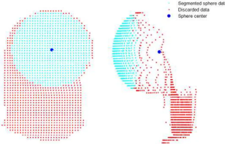
The considerations and the process involved in developing the sphere segmentation and fitting algorithm have been detailed by Rachakonda et al. [2], and this process to determine a sphere center has been adopted by the ASTM E3125-17 standard. The algorithm works on data corresponding to a single sphere. Additional data that are not a part of the sphere are allowed, if they are behind the sphere surface. An initial sphere center is calculated using the “closest point algorithm” [2]. Subsequently, a “cone-cylinder algorithm” [2] is used to find the sphere center, and this process is iterated 5 or more times to calculate the final center of the sphere. Fig. 1 shows one example of the data segmentation that was performed using the algorithm described in this paper.
1 Disclaimer: Commercial equipment, software, and materials may be identified in order to adequately specify certain procedures.
Such identification does not imply recommendation or endorsement by the National Institute of Standards and Technology, nor does it imply that the materials, software, or equipment identified are necessarily the best available for the purpose.
4.
Implementation of the Algorithm
The software code was developed using three different software suites, namely, MATLAB, Octave, and Python. The corresponding versions and dependent toolboxes/packages/modules are listed in the software specifications (Sec. 2). This software code may work in other versions of these suites and other operating systems where these suites are available, but compatibility is not guaranteed.
Code for demonstrating the functionality is provided as script files (demo1.m and demo1.py) along with sample data sets in the software download. To test the code, run demo1.m using MATLAB/Octave and demo1.py using Python. The main functions that are required (and provided as a download) are listed and described below. For all three functions, the input data format should be in the form of an N×3 matrix (N rows and 3 columns); the units of the calibrated sphere radius and that of the data must be the same.
1. coneCylAlgoE57(): This is the algorithm that takes the point cloud data and the calibrated radius as input arguments and returns the segmented data, discarded data, and the sphere center (depicted in Fig. 1 as cyan points, red points, and a blue point, respectively).
2. sphereFitLSQ1_conR(): This is a function that takes the point cloud data and a known radius as input arguments and returns the sphere center. This function does not perform any segmentation. It implements an orthogonal nonlinear least-squares algorithm by constraining the radius. This function uses the Levenberg-Marquardt routine available in all the three software suites. 3. sphereFitLSQ1_uncR(): This is a function that takes the point cloud data as an input argument
and returns the sphere center and the fitted radius. This function is implemented very similar to the previous function sphereFitLSQ1_conR(); i.e., this function implements an orthogonal nonlinear least-squares algorithm but does not constrain any parameter. This function is not required for implementing the segmenting method described in this paper, but it is provided as an auxiliary function for additional data analysis.
The results from the code implemented using the three software suites should be, in theory, identical and should result in the exact number of segmented points. In reality, even though the number of segmented points was the same for the data sets provided in the download, the centers obtained by these software implementations were slightly different. It should be noted that the final data sets obtained using different software suites may have the same number of points while having slightly different points. The maximum distance between the centers of any data set obtained by each of the software implementations was <1 nm, an
Fig. 1. Two views of data points from a TLS showing the result of segmentation performed using the algorithm described in this paper.
Volume 123, Article No. 123006 (2018) https://doi.org/10.6028/jres.123.006
Journal of Research of the National Institute of Standards and Technology
4 https://doi.org/10.6028/jres.123.006
insignificant amount. This difference could be attributed to the implementation of the nonlinear least-squares minimization routine in these software suites, the discussion of which is beyond the scope of this paper.
5.
Testing and Validation
The software described in this paper was developed and tested using Windows 7 (Enterprise, 64-bit version) and requires the Optimization toolbox for MATLAB R2015b, the “optim” package for Octave 4.2.1, and Numpy, Scipy, and MatPlotLib modules for Python 2.7. These dependencies are currently available on Windows, Mac, and Linux for all three suites, but the code was tested only on Windows 7 Enterprise 64-bit.
The software was tested on over 1000 data sets of sphere scans from multiple TLSs, of which 10 nonproprietary data sets are included along with this software. In all the instances, the software performed without any errors. The segmented data were visually inspected to ensure that data points that did not belong to the sphere were excluded in the final sphere center calculation. The software does not perform any input validation; however, demo1.m and demo1.py demonstrate application of the software using delimited text files of TLS scan data.
6.
Summary
This paper describes an algorithm to determine the sphere center as mandated in the ASTM E3125-17 standard, and an implementation of the algorithm using three different software suites is provided as a download. All three implementations were tested on hundreds of data sets, and they resulted in the same number of segmented points that are devoid of points that do not belong to the sphere.
7.
References
[1] ASTM International (2017) ASTM E3125-17 Standard Test Method for Evaluating the Point-to-Point Distance Measurement Performance of Spherical Coordinate 3D Imaging Systems in the Medium Range (ASTM International, West Conshohocken, PA). https://doi.org/10.1520/E3125-17
[2] Rachakonda PK, Muralikrishnan B, Cournoyer L, Cheok GS, Lee VD, Shilling KM, Sawyer DS (2017) Methods and considerations to determine sphere center from terrestrial laser scanner point cloud data. Measurement Science and Technology 28(10):105001. https://doi.org/10.1088/1361-6501/aa8011
About the authors: The authors are involved in developing documentary standards for evaluating
dimensional metrology instruments such as 3D scanners.
Prem Rachakonda is a mechanical engineer in the Engineering Physics Division at NIST. Bala Muralikrishnan is a mechanical engineer in the Engineering Physics Division at NIST. Luc Cournoyer is a Senior Technical Officer at the National Research Council of Canada, Ottawa, Canada. Daniel Sawyer is the group leader of the Dimensional Metrology Group in the Engineering Physics Division at NIST. The National Institute of Standards and Technology is an agency of the U.S. Department of Commerce.