ANALYSIS OF THE LASER GROOVING PROCESS
FOR CERAMIC MATERIALS
by
WOO CHUN CHOI
Bachelor of Science
Seoul National University, Seoul, Korea
(1982)
Master of Science
Seoul National University, Seoul, Korea
(1984)
SUBMITTED IN PARTIAL FULFILLMENT
FOR THE REQUIREMENTS FOR THE DEGREE OF
DOCTOR OF PHILOSOPHY
[N MECHANICAL ENGINEERING
at the
MASSACHUSETTS INSTITUTE OF TECHNOLOGY
September 1989
Massachusetts Institute of Technology
The author hereby grants to M.I.T. permission to reproduce and to distribute copies of this
thesis document in whole or in part.
Signature of Author
Certified by
Accepted by
Signature redacted
Department of Mechanical Engineering
September 10, 1989
Signature redacted
Prof/George Chryssolouris
'_____Signature
redacted
Prof. Ain A. Sonin
-Departmental Committee on Graduate Students
ARCHIVES
ANALYSIS OF THE LASER GROOVING PROCESS
FOR CERAMIC MATERIALS
by
WOO CHUN CHOI
ABSTRACT
In order to overcome the low energy efficiency associated with conventional laser machining, a three-dimensional laser machining process has been developed utilizing two laser beams. In this process each laser beam creates a groove on the workpiece surface. When the two grooves converge, a large volume of material is removed. In this manner, large-scale material removal processes such as turning, threading and milling processes can be implemented.
An essential element in the three-dimensional machining is single beam grooving. To describe the grooving process, analytical and numerical analyses were performed, which account for beam power, heat conduction and material ablation. The theoretical analysis was also modified to account for changing conduction area and direction.
In ceramic materials the primary phase change is melting. The molten material has to be removed in order to yield deep and clean grooves. Unlike in through-cutting, molten material removal is difficult in grooving due to the groove geometry. To eject molten material, an off-axial supersonic jet is used. Both theoretical analysis (through modification of the laser grooving analysis) and experimentation (through a statistical experimental design approach) were performed to understand gas-jet-aided grooving, find the jet condition for maximum grooving effectiveness and determine a dominant jet parameter affecting groove formation.
Comparison between the theoretical and experimental results were made, and showed a good agreement. Among various jet parameters, reservoir pressure is found to be the most important parameter, and the best jet condition is found. A significant improvement in energy efficiency was achieved in the three-dimensional machining compared with single beam laser machining processes.
ACKNOWLEDGEMENT
I would like to thank my adviser, Prof. George Chryssolouris, for his continuous encouragement and advice. I really enjoyed working for him. I would also like to thank Prof. Mikic and Prof. Sonin for their valuable advice. I wish to thank Paul Sheng for valuable comments. I dedicate this thesis to my parents who have been giving me moral support all the time.
TABLE OF CONTENTS
Title Abstract Acknowledgement Table of Contents List of Figures List of Tables 1. Introduction2. Theoretical analysis of the laser grooving process
2.1 Problem definition
2.2 Groove formation: heat transfer analysis 2.2.1 Analytical solution
2.2.2 Modified solution
2.2.3 Numerical solution2.3 Gas jet interaction and molten layer behavior 2.4 Three-dimensional machining
3. Experiments results and discussion 3.1 Gas jet test
3.1.1 Flat-workpiece test 3.1.2 Grooved-workpiece test 3.1.3 Real-size-groove test 3.2 Grooving test
3.2.1 Effects of an off-axial gas jet
4. Conclusions
References
Appendix
A. Gas Jet Effects on Laser Cutting
B. Fortran Program for Numerical Analysis C. Fortran Program for Regression
LIST OF FIGURES
Fig. 1.1: Three-Dimensional Laser Machining Concept.
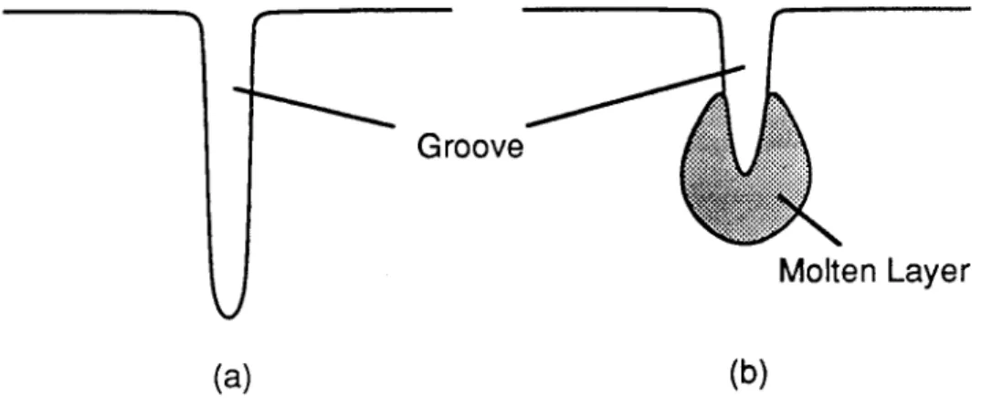
Fig. 1.2: Laser Machine for Three-Dimensional Laser Machining. Fig. 1.3: Molten Layer Effect on Groove Formation.
(a) gas jet is effective; (b) gas jet is not effective.
Fig. 2.1: Schematic of Gas-Jet-Aided Laser Grooving. Fig. 2.2: Single (a) and Multiple Pass (b) Laser Grooving. Fig. 2.3: Analytical Model for the Laser Grooving Process. Fig. 2.4: Control Volume inside Solid Medium.
Fig. 2.5: Isotherm Surfaces in the Conduction Direction. Fig. 2.6: I(o) vs.
a.
Fig. 2.7: Ratio of Conduction Heats Predicted by Analytical and Modified Solutions. Fig. 2.8: Configuration of the Laser Beam and a Coordinate System (a) and Boundaries for
Numerical Analysis (b).
Fig. 2.9: Control Surface at Cutting Front in Numerical Analysis. Fig. 2.10: Driving Forces for Molten Material Removal.
Fig. 2.11: Under-Expanded Supersonic Jet with a Mach Shock Disc. Fig. 2.12: Molten Layer and Control Volume.
Fig. 2.13: Numerical Domain and Boundaries for Three-Dimensional Machining.
Fig. 3.1: Experimental Apparatus and Wokpieces for Gas Jet Tests. Fig. 3.2: Convergent Nozzles Used in Gas Jet Tests.
Fig. 3.3: Workpiece Pressure vs. Reservoir Pressure for Nozzle/Workpiece
Distance Variations (nozzle exit diameter = 0.1 cm, and jet attack angle = 90'). Fig. 3.4: Reservoir Pressure and Jet Structure.
Fig. 3.5: Under-Expanded Supersonic Cell Dimension vs. Reservoir Pressure [64]. Fig. 3.6: Shock Types Depending on Nozzle/Workpiece Distance.
Fig. 3.7: Workpiece Pressure as a Function of Radial Distance from the Jet
Targeting Point (nozzle/workpiece distance = 0.4 cm, nozzle exit diameter = 0.1 cm , and
jet
attack angle = 900).Fig. 3.8: Jet Separation and Surface Flow Visualization.
Fig. 3.9: Pressure Difference vs. Reservoir Pressure for Groove Depth Variations
(other conditions: 0.4cm nozzle/workpiece distance, 0.1cm nozzle exitFig. 3.10: Pressure Difference vs. Reservoir Pressure for Groove Width Variations (other conditions: 0.4cm nozzle/workpiece distance, 0.1cm nozzle exit diameter, 900 jet attack angle, 0.74cm groove depth, 450 cutting front angle). Fig. 3.11: Pressure Difference vs. Reservoir Pressure for Groove Angle Variations
(other conditions: 0.4cm nozzle/workpiece distance, 0.1cm nozzle exit diameter, 900 jet attack angle, 0.74cm groove depth, 0.076cm groove width).
Fig. 3.12: Pressure Difference vs.Reservoir Pressure for Nozzle/workpiece Distance Variations.(other conditions: 0.1cm nozzle exit diameter, 900 jet attack angle, 0.74cm groove depth, 0.076cm groove width, 450
cutting front angle).
Fig. 3.13: Pressure Difference vs. Reservoir Pressure for Jet Targeting Distance Variations.(other conditions: 0.4cm nozzle/workpiece distance, 0.1cm nozzle exit diameter, 900 jet attack angle, 0.74cm groove depth, 0.076cm groove width, 450 cutting front angle).
Fig. 3.14: Pressure Difference vs. Reservoir Pressure for Jet Attack Angle Variations.(other conditions: 0.4cm nozzle/workpiece distance, 0.1cm nozzle exit diameter, 0.74cm groove depth, 0.076cm groove width, 450 cutting front angle).
Fig. 3.15: Pressure Difference vs. Reservoir Pressure for Nozzle Exit Diameter Variation.(other conditions: 0.4cm nozzle/workpiece distance, 900 jet attack angle, 0.74cm groove depth, 0.076cm groove width, 450 cutting front angle).
Fig. 3.16: Flow Directions of Molten Material. Fig. 3.17: Jet Flow Separation.
Fig. 3.18: Complete and Fractional Factorial Designs.
Fig. 3.19: Main Effect of Jet Targeting Distance on Pressure Difference. Fig. 3.20: Main Effect of Nozzle/Workpiece Distance on Pressure Difference. Fig. 3.21: Main Effect of Reservoir Pressure on Pressure Difference.
Fig. 3.22: Cross-Sectional Groove Shapes for Various Jet Conditions.
P = 500W, v = 0.508 cm/s, number of passes = 1: (a) 3 bar coaxial (b) 1.5 bar coaxial and 5 bar off-axial reservoir pressure
P
=
500 W, v
=
1.02 cm/s, number of passes =2: (c) 3 bar coaxial (d) 1.5 bar
coaxial and 5 bar off-axial reservoir pressure.Scanning Velocity
=
0.508 cm/s, and Number of Passes
=
2.
NWD (cm)
JAA(
0)
JTD (cm)
(a)
0.4
60
1.22
(b)
0.3
45
0.85
(c)
0.1
60
0.78
(d)
0.2
60
1.22
Fig. 3.25: Main Effect of Nozzle/Workpiece Distance on Groove Depth.
Fig. 3.26: Main Effect of Jet Targeting Distance on Groove Depth.
Fig. 3.27: Main Effect of Jet Attack Angle on Groove Depth.
Fig. 3.28: Grooving Test Setup for Test II and II.
Fig. 3.29: Main Effect of Nozzle/Workpiece Distance on Groove Depth.
Fig. 3.30: Main Effect of Jet Targeting Distance on Groove Depth.
Fig. 3.31: Main Effect of Reservoir Pressure on Groove Depth.
Fig. 3.32: Main Effect and Sensitivity of a Parameter.
Fig. 3.33: Variations of Parameters.
Fig. 3.34: Groove Depth vs. Nozzle/Workpiece Distance.
Fig. 3.35: Groove Depth vs. Jet Targeting Distance.
Fig. 3.36: Groove Quality on Two-Dimensional Plane of Nozzle/Workpiece
Distance and Jet Targeting Distance.
Fig. 3.37: Parameter Conditions for Signal-To-Noise Ratio Calculation.
Black Point: conditions where SN ratios are calculated
Gray Point: conditions due to the variations of parameters.
Fig. 3.38: Geometric and Dynamic Similarity between Two Configurations.
Fig. 3.39: Groove Depth vs. Non-Dimensional Energy in Laser Grooving (A1
203).
Fig. 3.40: Test Setup for Two-Beam-Laser Machining.
Fig. 3.41: Groove Depths for Single and Double Beam Grooving (A1
203).
LIST OF TABLES
Table 3.1: Parameter Ranges for Groove Tests.
Table 3.2: Conditions for High Pressure Differences in Grooved-Surface Test. Table 3.3: Parameter Levels for Real-Size-Groove Test.
Table 3.4: Physical Properties of Aluminum Oxide (A1203). Table 3.5: Jet Conditions and Corresponding Groove Depths. Table 3.6: Main Effects and Sensitivities of Three Jet Parameters. Table 3.7: Jet Parameters and Groove Depths (Test III).
CHAP 1.
INTRODUCTION
The laser stands for light amplification by stimulated emission of radiation. Since laser machining was first demostrated in 1960, it has become a significant part of industrial practice. The high power densities that laser beams create on workpiece surfaces have been a particular asset in drilling and cutting operations.
As a non-contact tool, laser beams offer a number of advantages for machining, such as no tool wear, no cutting forces, no chattering, etc. Since laser machining depends only on the thermal properties of a workpiece material instead of its mechanical properties, laser beams can easily process advanced engineering materials, such as ceramics and composites. On the other hand, laser machining has certain drawbacks, such as low energy efficiency and constraints on machining geometries (limited to one-dimensional drilling, two-dimensional scribing, and cutting operations).
A three-dimensional laser machining concept has been developed [1,2] in which two laser beams create blind kerfs in a workpiece. When the two kerfs converge, a volume of material is removed (Fig. 1.1). According to the concept, the three-dimensional machining process is flexible in terms of shapes and forms that can be worked, and is
substantially more energy efficient than single-beam ablation of the entire volume of material, since energy is only consumed on the grooves to be made and not on the entire volume of material to be removed.
In order to perform three-dimensional laser machining, a dual beam CO2 laser machine is used in the Laboratory for Manufacturing and Productivity, MIT. As shown in Fig. 1.2, the laser machine consists of three parts: laser cavity, beam delivery system, and workpiece positioning system. The two laser beam tools can be rotated around a central axis. A workpiece is translated in two directions and rotated by three step motors, which are controlled by a micro-computer.
The material removal rate as well as the dimensional accuracy of the three-dimensional laser machining process is directly related to the depth of the grooves [3,4]. Therefore, laser grooving is an essential element of the three-dimensional laser machining. In order to understand the three-dimensional machining better, the grooving process should be studied first. In the laser grooving process, a blind kerf is formed by a single laser
7-Laser Beams
C
Ing
(a) Laser Turning
(b) Laser Milling
Fig. 1.1: Three-Dimensional Laser Machining Concept
Y
Central Axis
CO Coherent
Laser Machine
Beam A
Rotation
Workpiece
Translation
X Translation
Fig. 1.2: Laser Machine for Three-Dimensional Laser Machining
A gas jet can be used to force the molten material from the groove to continuously expose new surface to the laser beam. If the gas jet is effectively utilized, the majority of beam through single or multiple passes over a workpiece. The grooving process depends on process variables (such as beam power, scanning velocity, number of beam passes, etc) and gas jet parameters (in situations where a molten layer is formed in the groove).
of beam diameter) straight groove can be made on the workpiece. On the other hand, if the
molten material is not effectively removed, it interacts with the laser beam and tends to
grow into a thick molten layer (Fig. 1.3). The molten material resolidifies in the groove,
causing a reduction in the groove depth as well as a deterioration in the surface quality.
This results in a rather wide groove with walls which are not straight. The use of a gas jet
reduces the molten layer thickness. A thin molten layer reduces the diversion of beam
energy to heating the molten material above the melting point. Also, the use of a gas jet
reduces the width of a melting front cross-section and increases the depth of the melting
front cross-section because of the energy conservation. In multiple-pass grooving, a
significant portion of the laser beam energy must be diverted to remelt the resolidified
material that was not removed by the jet during the previous beam pass. The use of a gas
jet minimizes the amount of resolidified material and, correspondingly, reduces the beam
energy loss to remelt the resolidified material.
Groove
Molten Layer
(a)
(b)
Fig. 1.3: Molten Layer Effect on Groove Formation
(a) gas jet is effective; (b) gas jet is not effective
This thesis addresses the effectiveness of using gas jets to improve groove depth
and surface quality in laser grooving. The objectives of this thesis are to understand the
physical mechanism in gas jet-aided grooving, to develop a theoretical model of grooving
and three-dimensional machining, and to find the effect of a gas jet on groove formation.
In order to achieve the objectives, the followings are considered:
Analysis
*
grooving with the aid of an off-axial jet
-
three-dimensional machining
* Experiments - gas jet test
- grooving test (aluminum oxide) - three-dimensional machining test
. Comparison between theoretical and experimental results
Background on Laser Machining
When laser radiation interacts with a solid, several thermal-related effects occur. Photon absorption at the surface is the first phenomenon. Depending on the intensity of the incident laser beam, heating and vaporization with photon penetration can occur at the moment of the laser interaction [5,6]. Material heating can occur for low beam intensities. The photon energy absorbed transforms instantaneously into thermal energy heating the surface, until the surface temperature reaches the phase transition temperature. As the melting and vaporization temperatures are reached, new phases and moving boundaries appear. Vaporization with photon penetration can occur for very high intensities. An extremely high intensity causes sufficient transmittance of the laser energy past the surface, resulting in the appearance of plasma. Due to heating inside the material subsurface temperatures exceed the vaporization temperature [7]. This high temperature causes a vapor explosion.
The laser induced plasma changes dramatically the conditions of material processing. The absorptivity vary suddenly at the interface from the moment that interaction starts. The temperature increase is accompanied by phase transition. Due to the temperature difference, heat is conducted into the medium. In la'er machining, phase change, conduction, and a moving heat source are involved.
Most of the theoretical work on laser machining heat transfer has centered on the solution of the heat conduction equation for a stationary or moving semi-infinite solid [8-11]. Heat conduction problems with moving heat sources have been originally treated in [12, 13]. Exact solutions were obtained for a number of problems with two phases [12]. Rosenthal [13] outlined the fundamentals of the theory of moving source of heat, and derived appropriate solutions for linear, two and three dimensional flow of heat in solids of
source moving with a constant speed along the x-axis, the temperature distribution around the heat source was determined. If heating occurs for long enough, the temperature distribution around the heat source soon becomes constant, and the end effects become negligible. This can be applied to any process where the heat source moves at a constant
velocity relative to a workpiece such as cutting and grooving. The problem of heating a
homogeneous slab of material induced by time dependent laser irradiance was studied in [14]. In [15] heat conduction was investigated in a moving semi infinite medium subject to laser irradiation.Drilling in which there is no relative movement between laser beam and workpiece has been investigated early. The initial stage of drilling is unsteady, since absorptivity changes significantly at the instant of laser interaction. Absorptivity, which depends on the interaction time, affects drilling performance. Absorptivity variation during laser drilling was investigated in many papers [16,17]. Time-dependent radiation reflectivity of the metals was found to account for most of the incident power in the initial stages of the interaction in [6]. In [18] the sequential steps of the plume evolution caused by a ruby laser pulse was investigated. They found that the laser intensity and absorptivity are the most important factors for drilling process. Drilling was performed over various materials [19-21]. Hole depth and shape were predicted as a function of absorbed intensity in [22].
Drilling is performed mostly with a pulsed laser, which by storing energy produces higher intensities evaporating a material more easily. For varying pulse lengths, the effects were investigated on laser drilling in [23]. Pulsed laser beams create a large temperature gradient inside the material because of its high intensity and short interaction time. This causes a large thermal stress which induces cracks in the material. In [24] the temperature profile and the tangential stress distribution of the laser-formed hole were calculated to indicate the magnitude of those factors that can influence the potential fracture of alumina material. In [25] residual stresses were measured from strain measurement near a hole. By calculating the transient and steady state temperature rise of laser irradiated metals, it was showed that values of the intensity that cause failure change drastically [26].
For such processes as drilling, cutting, and grooving, molten or vaporized material
should be removed, in order to form a hole or kerf. Unlike cutting or grooving, where
high pressure gas jets are used for the purpose of material expulsion, beam interaction timeis relatively short for drilling, and thus a gas jet is not effective. Instead, the explosive
vaporization at the subsurface results in very rapid and efficient material removal [7].Material is removed in the form of liquid and/or vapor. Expulsion mechanism of liquid
material during drilling was investigated in [16,18,22].
To predict an explosive
vaporization, several models have been developed treating laser beam power as a heat
source inside the medium rather than as a surface interaction [7,15,27]. In their models,
penetration of the laser beam into the material was allowed by a distributed heat source
coupled to a moving boundary. With the models the temperature distribution inside the
medium was calculated, and a peak temperature inside the medium was predicted.
Usually the term laser cutting implies laser "through" cutting in which a laser beam
penetrates through the entire thickness of the workpiece and advances parallel to the surface
of the workpiece. Laser cutting is the most widely used machining process. In the laser
cutting of metals, a laser beam heats up, and melts or evaporates a metallic workpiece,
while a gas jet is used to drive out the molten or vaporized material. Depending on the
phase of material removed, laser cutting is divided into sublimation and fusion cutting. In
the case of sublimation cutting, the material is vaporized, and pulsed solid state lasers are
mainly used. In the case of laser fusion cutting the material is melted in the region of the
cutting seam and is then blown out with the aid of an inert gas jet. If a gas jet which is not
inert (i.e., oxygen) is used, the process is called a reactive gas assisted cutting, where a
reaction energy serves as an additional heat source in addition to the laser beam energy.
In laser cutting, maximum cutting speed is of interest. The effect of cutting
parameters in laser gas cutting on the qualities of cuts has been studied in stainless steel
plates using a 1 kW C02 laser in [28]. It was found that tandem nozzle cutting was
significantly more effective in improving surface roughness and flatness of the cut than
coaxial jet alone. In [29], based on the absorptivity calculated over the cutting kerf, a
cutting model was developed. Schuocker et al. [30] suggested a model based on the
assumption that the momentary end of the cut is covered by a thin molten layer which loses
mass by evaporation and by ejection of liquid material. In [31] a relationship between the
power density incident on a material and the resulting cutting speed was developed in terms
of the thermal properties of the material. In [32], on the basis of the wave equation, the
relation between the degree of absorption and the inclination of the cutting front were
obtained for different laser modes, types of polarization and focal positions. Based on the
absorptivity, cutting parameter effects on laser cutting were investigated. In [33] a
parametric study of pulsed laser cutting of thin metal plates was reported. In [34] a relation
between maximum cutting thickness and cutting speed for a given laser power was
For many materials, periodic striations are observed on the cut surfaces. The occurrence of striations is undesirable since it deteriorates the surface quality. The striations on the cut surfaces are due to an unsteady motion of the melt. When a laser beam heats up material to a temperature to ignite in the presence of the oxygen, the resulting combustion pushes molten material radially away from the laser spot. The combustion front comes to rest and the subsequent encroachment of the laser beam on the new cutting front repeats the oxidation initiation process. The resulting cut surface consists of regularly spaced striations. In [35] a dynamic solution predicted a periodic oscillation superimposed on the steady state temperature of the melt. A stability analysis associated with ripple formation was presented in [36].
In the laser welding processes, material removal is not involved. In [37] the absorption of a laser beam by a workpiece was described and the physical, chemical, and thermal changes were shown to cause welding of the workpiece. The power absorbed at the surface goes into melting, vaporization, and heat conduction into the medium. If the beam is sufficiently intense, the energy is deposited in a cavity. This cavity is known as a keyhole, which is formed relatively quickly at the start of the run, and is filled with gas or vapor, and surrounded by liquid. On the rear side of the keyhole the metal freezes as heat is conducted away from it into the solid, and this solidification forms the weld. The depth of the keyhole is much greater than the penetration depth of photons into the solid and liquid phase, and is limited by the beam power or by the absorption of the beam. In [38] a relationship was shown for the dependence of maximum single pass laser weld penetration on power, and a range of laser welding applicability was determined. In [39] a thermal analysis for laser heating and melting materials was derived for a Gaussian source moving at a constant velocity.
The penetration is opposed by the flow of molten material into the keyhole, and a balance of these effects results in a steady state hole profile. There are three other forces which should be considered in general: gravity, surface tension, and vapor pressure. Gravity is a restoring force. Temperature gradients on the melt surface between the laser beam interaction spot and the intersection line of the solid-liquid interface generate a surface tension gradient. The surface tension pulls the liquid material from the hot central region to the cold outer region. Surface tension reduces the depth of penetration typically by a factor of about three [40]. There is some vapor flow across the cavity providing the pressure
which drives the liquid. The pressure inside the cavity is governed by the hydrostatic pressure in the liquid, and by the viscous forces acting on the vapor stream [41].
Flow conditions in the horizontal plane determine the dimensions of the weld. Material is moved around the advancing vapor cavity mainly by liquid flow. In [41] the conditions of energy and material flow during beam welding were investigated theoretically to determine the factors which govern the shapes of the vapor cavity and of the molten zone. The flow of the liquid and surface tension tends to obliterate the cavity, while the vapor which continuously generated tends to maintain the cavity. Return flow is set up because of the existence of the solid liquid interface. This recirculating flow is much faster than the scanning motion [42]. As the flow develops, convection becomes the dominant energy transfer mechanism. Based on a perturbation solution due to the small scanning velocity, a weld pool shape was obtained. In [43] relationships between the weld width, the power absorbed per unit thickness of the workpiece, and the speed of welding were investigated from a mathematical model for the heat transfer and fluid flow in the molten metal surrounding a keyhole. In [44], a simple model was developed to determine keyhole shapes and the variation in the keyhole depths.
The flow of liquid due to surface tension gradients and material lost by vaporization create a depression of the liquid surface beneath the beam and ridging of the liquid surface elsewhere. As the beam passes to other areas of the surface, this distortion of the liquid surface is frozen in, creating a roughened rippled surface. In [45] it was examined how surface tension gradients cause significant rippling of a laser melted surface, and it was shown that rippling from surface tension gradients can be avoided if during surface melting the laser beam velocity exceeds a critical velocity.
In grooving a laser beam does not cut through the entire workpiece. Little work has been done on the grooving process. A numerical analysis on laser grooving was done, by assuming immediate evaporation of the solid material due to the laser irradiation in [46]. The governing equation in this study was a groove formation equation, and the temperature distribution inside the medium was assumed. A model distinguishing the process into different regions was suggested in [47]. Experimental results on laser grooving were reported in [48]; grooves on metallic and ceramic materials were produced using a single laser beam. As an element of a three-dimensional laser machining, laser grooving was
investigated in [49].
CHAP 2. THEORETICAL ANALYSIS OF THE
LASER GROOVING PROCESS
2.1 Problem Definition
As a component of three-dimensional laser machining, the grooving process exhibits complicated characteristics, such as three-dimensional heat transfer, 2 phases, moving boundary, spatially distributed heat source, gas jet interaction, etc. (Fig. 2.1). Furthermore, there is interdependence among the behavior of a gas jet, molten layer and groove geometry. A gas jet creates a pressure field on a cutting front, which affects molten layer thickness distribution. A cutting front is defined as a surface interacted by the laser beam. A molten layer interacts with the laser beam as well as the gas jet through the cutting front, and with a solid medium through the melting front. Conduction heat from the molten layer melts solid material, and is transferred into the solid. From an analysis point of view, grooving can be decomposed into three parts: gas jet interaction, molten layer behavior, and groove formation.
Laser,
Beam NozzleGas Jet
Molten Layer CuttingFront
Fig. 2.1: Schematic of Gas-Jet-Aided Laser Grooving.
The following assumptions are made to simplify the analysis without substantially sacrificing its accuracy:
1. The relative speed of the laser beam travelling over the workpiece is constant.
2. The workpiece material is isotropic and has constant properties. Among the material properties, thermal conductivity varies significantly with temperature: for example, the thermal conductivity of aluminum oxide varies from 0.36 W/cm*C at room temperature to 0.064 W/cm0C at the melting point. The conduction heat into the interior of the workpiece depends on the conductivity and the temperature gradient at the melting front. If conductivity is assumed as the value at the melting front, the real temperature gradient at the melting front is not significantly different from the temperature gradient based on conductivity varying as a function of temperature. Thus groove formation is not significantly affected by the conductivity variation, while the temperature distribution inside the solid which is not close to the melting front depends greatly on the conductivity variation.
3. Melting is the only significant phase change that occurs, and possible evaporation of some of the liquid material is neglected. This assumption is based on the fact that in engineering materials such as metals the predominant phase change for laser grooving at commercially available laser powers is melting. In reality, however, it may be that some evaporation occurs, depending on the interaction time of the beam on the material. Furthermore, in materials such as composites and plastics, evaporation is the predominant phenomenon.
4. A gas jet removing the molten material from the groove does not interfere with the laser beam. The use of gas jets is a critical factor in producing thin
straight kerfs.
5. The laser beam spot size remains constant. However, in numerical analysis the beam defocusing effect is considered.
6. The material is opaque; that is, that the laser beam does not penetrate
appreciably into the medium, which exhibits constant absorptivity. The
effect of polarization on absorptivity is not considered.
7. In the literature, a variety of phenomena related to laser beam interaction with a workpiece material has been reported such as small explosions of the workpiece material, etc. These phenomena have not been considered in this analysis.
2.2
Groove Formation: Heat Transfer Analysis
When a very effective gas jet is used, the molten layer thickness is negligible, and the convection effect of the molten material becomes insignificant. Without considering the convection effect of the gas jet, absorbed laser beam power is used either to melt material or to be conducted into the solid. In this situation, groove depth can be estimated without considering gas jet interaction and molten layer behavior. This method is also applicable to the cases where workpiece material does not melt but vaporizes. Later, the groove formation solution will be modified to account for a molten layer with finite thickness.
2.2.1 Analytical Solution
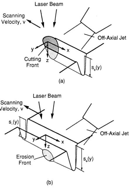
Fig. 2.2 schematically shows the process of laser grooving for (a) single pass and (b) multiple passes of the laser beam over the workpiece. The Cartesian coordinates system (x, y, z) is moving with the laser beam which has an intensity profile J(x,y) projected onto the groove surface. s_(y) (Fig. 2.2(b)) is the depth of the pre-existing groove surface formed by previous laser passes, s(x,y) is the depth of the current groove surface, and s+(y) is the depth of the already developed groove surface during this pass.
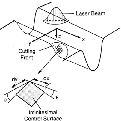
In order to gain a quantitative understanding of the effect on the process of the different process parameters, an infinitesimal control surface (Fig. 2.3) on the cutting front surface can be studied. The control surface is inclined at an angle 0 with respect to the x-axis and at an angle
p with respect to the y-axis, and is subjected to a laser beam of
intensity J(x,y).A three-dimensional heat conduction equation governs the heat transfer problem with a moving heat source:
Laser Beam
Scanning
Velocity,
v
Off-Axial Jet
Y
xCutting z
Front
s+(y)
(a)
Laser Beam
Scanning
Velocity, v
s_(y)
Off-Axial Jet
y xz
Erosion
+Y
Fronts(y
(b)
Fig. 2.2: Single (a) and Multiple Pass (b) Laser Grooving
a2T a2T
F tT
kax2
ay2 Dz2 p aX(2.1)
where k is thermal conductivity, T is temperature, v is scanning velocity, p is the density of the material, cp is the specific heat of the material
Laser Beam
z
y
Cutting
Front
dy
dx
Infinitesimal
Control Surface
Fig. 2.3: Analytical Model for the Laser Grooving Process
2 V0T
V T-=
VT
x(2.2)
where a is the thermal diffusivity of the workpiece
subject to:
at the cutting front surface : T=T,
x-4 oo, y-4 oo, z-+oo : T=T0 (2.3)
where TS is the surface temperature, and To is the ambient temperature.
In order to simplify Eq. (2.2), it is assumed that heat is conducted in the direction
normal to the surface of the cutting front. Accordingly the following relations can be
derived.
aT YT ax j(2.4) T DT -_tan$ a
a4
(2.5) T aTT 1/2-in-
-(2.6)
where n is a coordinate normal to the cutting front surface. Additionally, the following
simplification is assumed.
2 T 2T
an
2(2.7)From Eqs. (2.4),
(2.5),
and (2.6), DT/ax can be related to aT/an.
aT
DT
tanO
(1 + tan2 0 + tan2
)1/2
aT(2.8)
tanO
where
wee =2 tan=2 1/2
(+ tan 0
+
tan $) (2.9)Eqs. (2.4) and
(2.5)
are correct at the cutting front, but not generally correct inside the
medium where the direction of n is not always perpendicular to the cutting front. Eq. (2.2)
can be simplified as:
$v aT
DT
subject to the following boundary conditions: at n=O, T=T,
as n-+oo, T=T0 (2.11)
The temperature distribution inside the medium can be determined as:
T-T - n
= a
(2.12)
The temperature gradient at the cutting front can be determined as:
C
a =
S (T- T)(2.13) The energy balance at the infinitesimal control surface is given by:
y
dTkaJ(dxdy) =-k dA d) rrg + pLv(dxdy)tanO
(2.14)
where a is the absorptivity of the material, L is the latent heat of fusion, and dA is an infinitesimal control surface area (Fig. 2.3)
dA = ((dxdy)2 + (dxtanO dy)2 + (dxdytan$) 2) 2(+ a2 112 1
=dxdy (1 + tan tan) =- dxdy tanO
(2.15)
Substitution of the temperature gradient (2.13) into Eq. (2.14) yields
kv
aJ= - (T - T ) tanO + pLv tanG = pv tan(cP(T-T) + L)
It is assumed that the laser beam has a Gaussian distribution intensity:
J
P
e- (X YYR 7cR(2.17) where P is the laser beam power, and R is the beam spot radius. The slope of the groove surface along the x-axis, tan6, can be determined as:
aPe
-(x+y yRe
7cR2tanO
=pv(c (T, -Td + L)
(2.18)
The change of the surface depth along the x-axis can be expressed as:
ds = dx tanG
(2.19)
and the surface depth can be determined by integrating from -oo to the current x position: X
s(x'y)
f
ds
+ s_(y)
(2.20)
or
x
s(x,y) = tanO dx + s_(y)
(2.21)
By substituting tanG into Eq. (2.21), the following expression for the surface depth s(x,y) can be obtained:
X
~aP
e-x+y YRs(x,y)= 2 dx + s_
xR pv(c (T -T) + L)
P (2.22)
The maximum depth of the groove sm. can be achieved along the center line of the groove (y= 0):
_x
2R2
sm 2
aPe
dx+ s_(O)
m R pv(c (T-T)+L)
(2.23)
Thus the increment of the groove depth (AD) for one pass of the laser beam over the workpiece, is
AD =s - s_(0)
(2.24) The temperature at the top surface T. along the center line of the groove is assumed to be the melting temperature Tm. Although T. varies from Tm at the cutting front to T. far away from the cutting front, the resulting error in groove depth should be negligible because the exponential term in Eq. (2.23) becomes negligible for the part of the surface where the temperature is not Tm* Consequently, AD due to one pass of the laser beam over the
groove can be obtained as:
aP 1,2R 2aP
AD ==
7rR 2pv(c(T, -
T)
+ L)n
1pvd(cp(T, - Td + L) (2.25)where d is the beam spot diameter, d=2R. The incremental groove depth is proportional to
P/vd, which is the energy input per unit area of the workpiece. Also, AD is small for
materials with high melting point and high latent heat of evaporation. In comparison with the groove depth in grooving, the kerf depth in through-cutting is mathematically derived in
Appendix A.
2.2.2
Modified Solution
The previous analytical solution can predict groove depths well especially when scanning velocity is relatively high. This is because the assumptions made in the analytical solution are valid only for high scanning velocities. In order to obtain a better analytical solution, two modifications are considered, compared with the analytical solution: change in conduction direction, and area change in the direction of conduction heat.
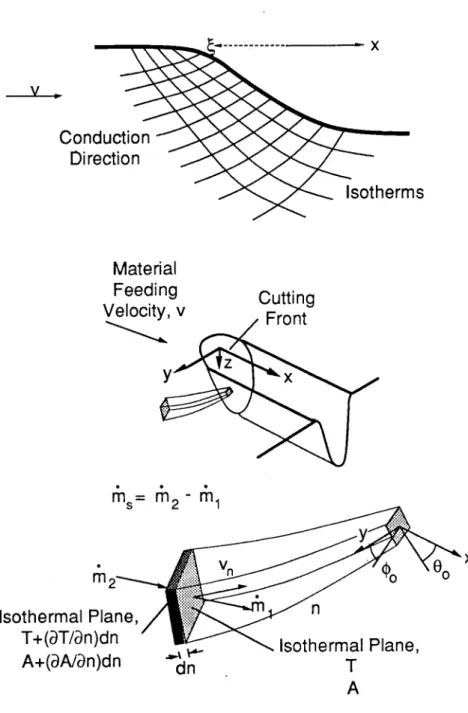
In order to derive the governing equation, an infinitesimal volume in the n-direction is considered, as shown in Fig. 2.4. The infinitesimal surface is inclined 0 and $ with respect to the x-, and y- axis, respectively. The area of heat conducted at n is A. Solid material is fed into and moved out of the control volume at a speed of v in the x-direction. The mass flow rates at 1 and 2 are
pvA
(2.26) 2= pv
A
+ (pvA)dn(2.27) where vn is the velocity component of material fed into the control volume in the n-direction. The net mass flow rate out of the control volume through the side walls is
m= 2- 1 (2.28)
The heat into the control volume is
dT
dA-(pc y AT- Td)
- kA p+ pcpvpA(T -T dn
(2.29)
Assuming that the temperature of the material moving out of the control volume through the side walls is T + (dT/dn)dn/2, the heat out of the control volume is
dT
d( dT
1 dT
--- - x
Conduction
Direction
~Isotherms
Material
Feeding
Cutting
Velocity, v
Front
z
y
x
Isothermal
T+(aT/an
A+(aA/a
ns=r
2 r 1 y r2 .. 00 0Plane,n
)dn
Isothermal Plane,
n)dn
d'
T
A
Fig. 2.4: Control Volume inside Solid Medium.
By equating heats in and out of the control volume, the following heat balance can be obtained
pcvAdT
kd
dT
pcnA
=-k
A-(
The area ratio g(n) is defined as A(n) divided by A(O) (infinitesimal cutting front area).
n =A(n)
A(O)
(2.32)Divided by A(O), which is independent of the n-coordinate, Eq. (2.31) becomes
Va
dT
g =n(2.33)
Boundary conditions are
n
= 0,T
=Tsn
-> o, T = To(2.34)
(2.35)
where Ts is the surface temperature, and To is the ambient temperature. From Eq. (2.33) the temperature distribution inside the solid can be derived.
n n -f
T=C i
0
0dn
+C
2 = C1B(n)
+C
2(2.36)
n hB(n) =
--e 0
dn
0(2.37)
Applying boundary conditions to Eq. (2.36), the temperature distribution is obtained as a function of n.
where:
d 9dT)
T -TO B(n)
=1-T -=1-T B(oo)(2.38)
For an arbitrary n, the velocity component vn is
tan8
v =v
(1 + tan20
+
tan2 )(2.39)
Let be a coordinate in the opposite direction of x ( = - x) from the cutting front surface into the solid. The increments of n and 4 can be related as:
(1 + tan
O +
tan2)
tanO(2.40)
From Eqs. (2.39) and (2.40)
vn dn = v d
(2.41)From Eq. (2.37), B(n) becomes
B(n) = 0 n - dh n AF 1
odnjadn--e
=
- e
dn
g
g
0
(2.42)
The area ratio can be determined as (Fig. 2.5):
A(n) dx'dy' (1 + tan2O + tan)2 A(0) dxdy (1 + tan2 0 + tan2 1
(2.43)
dxdy (1+ tan
2tan2
2 (1 + tan
2O + tan
2o)
B( )
f
etanO
d2112o
dx'dy' (1 + tan0 + tan2
(2.44)
The inclination of the cutting front surface (00 and $.) is independent of n and
.
Thus,
(1 + tan2 0+ tan2
14
B()tan
0 a3
dxdy
tanO
0dx'dy' tanO
(2.45)As shown in Fig. 2.5, the area ratio, dx'dy'/dxdy, can be approximated as:
dx'dy'
dxdy
-(R +()2R
2
2 (1+k'2
(2.46)dy
dx'
dA dy
dx
dA
Conduction
00
Direction
YO
Infinitesimal Surface
on the
Cuting
Front
Fig. 2.5: Isotherm Surfaces in the Conduction Direction.
Therefore, B(4) becomes
B( )
=(1 +tan
2O
0+
tan2O)"2 4tanO
f
o 01
a( tanO,1 + +(2.47)
or
(1
+
tan
2 +tan20
tanI1
tan I )2ea
ta
d4
0In order to determine I( ), the slope ratio, tanOO/tanO should be expressed as a function of
.
Since 0=e
0at =O and 0=9
0as 4-+oo, the angle ratio can be assumed as:
tanG
-an
=e
(2.50) where b is a characteristic length which is approximated as the beam spot diameter, d. Then I( ) becomes
1
+ I =e
b)2 d 0 1(2.51)
Define 1 such as: where
(2.48)
T
+
(2.52)
I( ) can be expressed as a function of T1.
R ( -+ 1R(i - 1)
I(R)=
-e
drii ll
Defining a as v 'vb 1)RR+ a= + R =b+(2.53)
(2.54)I(T) can be expressed as:
I(ij)=Re'
f
e-07
dII1T1
(2.55) I(oo) can be determined as:
I(oo) = R e' e dT = R + aea Ei(-a)
1 1
(2.56)
I(oo) represents a characteristic length of a heat affected zone in the 4 direction. Fig. 2.6 shows that I(oo) decreases monotonically with increase in a. Since a is a linear function of the scanning velocity, I(oo) is large for small scanning velocities and small for large scanning velocities.
I
0.006 -0.004 -0.602 -0.000 .1 1 10 100 Fig. 2.6: I(oo) vs. Y.The heat balance at the cutting front is
(
dT) /aJ = pLvtanO0 -k
(
(1 + tan2e0+ tan2 ) (2.57) The temperature gradient at the cutting front can be determined from the temperature distribution. dT (T - Td) dB (0) Bdn ) n0(2.58) Since dB(O)/dn isn
dB(O) n =1 = 1 a = dn e)
n=O (2.59)S(dT) - k
k(T, -
T)
B(oo)The heat balance at the cutting front surface can be written as:
k(TS - T )2 212
aJ = pLvtan60 + B (1 + tan2 0+ tan2 O
aJ = pLvtan0 + k(T- tan k(T, -
T
+ (o
I.o) jtaflO0 aJ =
(pLv
The cutting front angle can be expressed as:
aP e-(x
+y 2 R2-e
tan 0 =
pR
k(T-
T)pLy
+The surface depth is
x
s(x,y) =
JtanO
dx
Depth increment by one laser pass can be determined as:
AD=
tanO6dx
*
W
(2.66)
(2.60)
(2.61)
(2.62)
(2.63)
(2.64)(2.65)
I
2aP AD
S1/2 d pLv + I(ooT
(2.67)
The second term of the denominator in Eq. (2.67) is related to the conduction heat. Compared with Eq. (2.25), Eq. (2.67) has a different denominator. This is because the changes in conduction direction and conduction area are considered in the modified solution. The ratio between the conduction heats predicted by the analytical and the modified solution can be obtained from Eqs. (2.25) and (2.67) as
pc v (T, - T) vI(oo) cc
(2.68)
As shown in Fig. 2.7, for large scanning velocities (or large a), the ratio becomes unity, which means that the conduction heat predicted by the analytical solution is the same as that by the modified solution. For small scanning velocities, the ratio becomes less than unity. Small scanning velocities allow large beam interaction time with the material, leading to large heat affected zones. The conduction heat predicted by the analytical solution is smaller than that by the modified solution. This means that the analytical solution does not predict accurately the variation of a heat affected zone with respect to the scanning velocity.
1.0 . 0.8 . 0.6 -5 0.4 -0.2 . 0.0 1 - l .1 1 10 100 . 1000
2.2.3 Numerical Solution
In the previous sections, two theoretical solutions were obtained. Since the two solutions were based on approximation of the temperature distribution inside a solid, they may not be accurate, if the approximation is not valid. Thus, a numerical analysis is needed to obtain a more accurate solution. For a numerical analysis, a limited region is taken into consideration, as shown in Fig. 2.8(b), due to the symmetry the plane (y = 0)
can be an adiabatic boundary.
x = Xmax : T/ax = 0 (2.69)
x = xm i Y = Ymax; z = zmin: T = To (2.70)
y = ymzm: iT/ay = 0 (2.71)
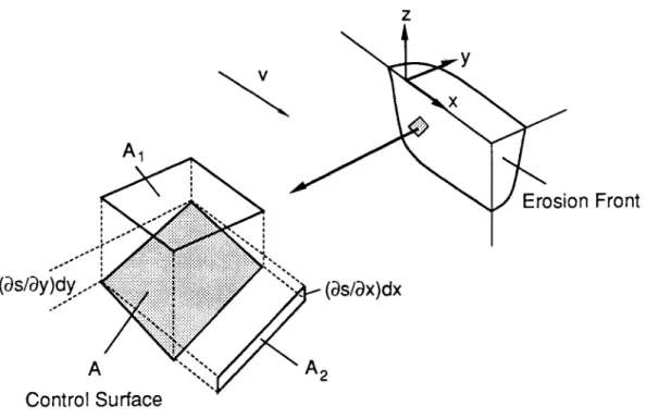
At the top surface, an energy balance is another boundary condition: the laser beam melts material and heats the surrounding material. In the control volume in Fig. 2.9, the following energy balance can be derived.
aJ(x,y,z)A=- k D)A + pLvA2
5 n 2 (2 .72)
where n is a coordinate normal to the surface pointing into the solid. From the geometry of the control volume, the following relations among areas can be obtained:
-1/2 A S2
(s
1+ a + a (2.73) A 2 a-1/2A)2
(T
2
s.741+
+2.74)z
Laser Beam
x
(a)
(X min'
YmaX
Z mai(X
min, Y min, Z m(YiXT
aT/ax =0
aT/ay =
0
T= TO
(xmax' Y
max Z mi(Xmax Ymin, Z miA
(b)
Fig. 2.8: Configuration of the Laser Beam and a Coordinate System (a) and Boundaries for Numerical Analysis (b)
Substituting of Eqs. (2.73) and (2.74) into Eq.(2.72) yields:
J(x,y,z) ( - T +
(a)yV(
-where: 112 =1+ aX+ a
(2.76)
(2.75)V
A
1(as/ay~d
(as/ax)dx
A
A2Control Surface
Fig. 2.9: Control Surface at Cutting Front in Numerical Analysis
The Gaussian laser beam intensity, including beam defocusing effect, can be expressed as: 2 2 J(x,y,z) = exp - (2.77
7tr(z)2
r(z)J
:(2.77) where: 1/2 2r(z) =R 1
+ R2(2.78)
Since the problem has a boundary whose location is to be determined as a solution, the method of lines is suitable for solving that type of problem. The method of lines has been developed for multi-dimensional heat transfer problems by Meyer [50,51]. According to the method of lines, Eq. (2.1) is transformed into a set of ordinary differential equation, by replacing all derivatives with finite difference forms except one with respect to z-direction:
z
y
x
v T+ - Ti T+ - 2T + T T j1- 2T + T,1 +
cx 2Ax Ax2 Ay2
(2.79)
Eq. (2.79) is a boundary-value differential equation, requiring boundary conditions at z =
zmin and the top surface. Eq. (2.79) can be converted into initial-value differential equations by the Riccati transformation. By defining a new function F,
BT
1
= -F(z)
az
k
(2.80)
Eq. (2.79) becomes:3F k
k
pcv
-- (T +T -2T) - (T +T. -2T)+2 -- (T T Ax 2Ay (2.81)The Riccati transformation takes advantage of a relation between the functions F and T:
F(z) = G(z)T + H(z) (2.82)
where G(z) and H(z) are the Riccati functions. From the Riccati transformation, three equations are resulted: two equations for a forward sweep and one for a backward sweep. In the forward sweep the top surface (cutting front) location is determined from the two equations, and in the backward sweep the temperatures along the line are calculated from one equation. The two equations for the forward sweep are:
dG
4k
1
d Ax2 k (2.83)dH
k
k
pcv
1
=-- (T +T ) y(T -T -T) kGHAx
2Ay2.84)
BTT-T
k =k 0 =GT+H
z
A
z
(2.85)
Since Eq. (2.85) holds for arbitrary T, the initial values for G and H can be determined as:
G(z id Azk
(2.86)
kT H(zi, )- 0
(2.87)
Since G in Eq. (2.83) is independent of temperature, the solution for G can be obtained prior to the calculation of temperature and surface profile. From the above initial conditions, G can be determined as:
1 +
G(z
)
+A
e '< G(zm ) - A Az- Y 1-G(zm ) + A(2.88)
where: 1/2 AA2k
+(2.89)
The function H can be solved by integrating Eq. (2.84) from zmm to the top surface.
The energy balance equation at the top surface can be used to check if ablation takes place. A function, C, is defined by arranging Eq. (2.75).
At each node, C is calculated in the forward sweep to check if the energy balance (2.75) is satisfied. Since the energy balance (2.75) is satisfied at the cutting front, the cutting front is located where C vanishes. If C does not change its sign before the previously made
surface is reached, no ablation takes place. In this case, the surface temperature instead of
the surface location is determined from the energy balance as follows:
aJ = k(GT,+H)
P (2.91)
In the backward sweep, the temperatures along the lines are determined from the top surface. The equation for the backward sweep is:
aT 1
T-K (GT + H) (.2
(2.92)
At the cutting front of the top surface, the temperature is the melting temperature, Tm, and at other surface is the temperature calculated from Eq. (2.91).
Iterations are repeated until the temperature and surface profile reach steady-state. During the calculation, updated temperatures, if available, are used. However, for the surface profile, the values calculated in the previous iteration are used, since a large slope can cause a numerical instability. A new temperature is obtained by an over-relaxation method:
-1+ C(T _ n-1)(2.9 )
The numerical computer program is listed in Appendix B.
2.3
Gas Jet Interaction and Molten Layer Behavior
During beam interaction with a material, a molten layer is formed. One of the main
goals in laser grooving is maximum expulsion of the molten material. In grooving, thedriving force for molten material expulsion is the pressure gradient along the cutting front, which can be created by the use of a gas jet.
In laser through-cutting, a coaxial jet is used to create a large pressure difference between the top and bottom of the kerf. This pressure difference, shown in Fig. 2.10 (a), forms a downward driving force, which expels molten material through the bottom of the kerf. In laser grooving, however, this driving force would cause molten material to be expelled towards the bottom of the groove and resolidify on the established groove wall. A favorable driving force for laser grooving (which expels material out from the top of the cutting front) can be formed by creating a pressure gradient with a high pressure at the bottom of the cutting front and low pressure at the top, as shown in Fig. 2.10 (b). Due to the geometric difficulty of removing molten material in grooving, an off-axial jet is used.
Investigations of gas jet effects in laser machining have been largely limited to the use of coaxial nozzles in through-cutting applications. In [52] high pressure (up to 20 bars) cutting with a variety of gas mixtures was investigated. In [53] the jet flow from nozzles used in laser through-cutting was investigated. A highly under-expanded jet is found to create a Mach shock disk above the workpiece that reduces the stagnation pressure at the workpiece and the cutting efficiency. In [54] the optimum values of parameters resulting in a high pressure on the workpiece were investigated. The effect of jet parameters on the pressure distribution at the cutting front in grooving was investigated in [55]. A theoretical analysis on a gas jet was done in through-cutting in [34]. In [56] the forces exerted by the gas jet on the molten layer in laser cutting were investigated theoretically by solving the equations of motion of the gas flow under the assumption that the gas flow is laminar within the cutting kerf, and the flow is subsonic. This assumption is not realistic, since the operating reservoir pressures in most applications cause the jet flow to be supersonic. In [56], it was found that momentum is transferred from the gas jet to the cutting front by a pressure gradient and friction, and both effects are of the same order. Donaldson et al. [57] found in their experiments the pressure and velocity distribution along the axis of various free jets (subsonic and supersonic) and investigated
the impinging jet behavior. In [58] a breakaway zone at the interaction between a
supersonic under-expanded jet and a flat plate was discussed. Related to the boost blastsituation, supersonic jet impingement on a surface was studied [59-61]. Although such
things as flow rate, nozzle diameter, etc. were on a larger scale in these studies than those in laser machining, the findings are helpful in understanding the flow field and pressureLaser Beam
Coaxial Jet
Cutting
&
Front
L
Hi
Material
Removal
Direction
Cutting
Direction
Molten
ayer
gh Pressure
Low Pressure
(a) Cutting
Laser Beam
Coaxial Jet
Cutting
- Direction
Off-axial
Jet
Cutting
Front
Molten Layer
Low Pressure
High
Pressure
Material
Removal Direction
(b) Grooving
Fig. 2.10: Driving Forces for Molten Material Removal.
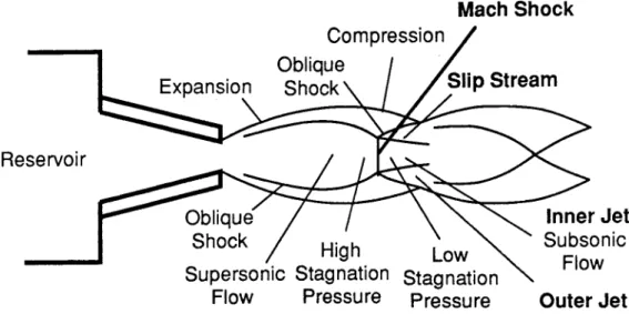
For a simply convergent nozzle, if a reservoir pressure is higher than 1.89 bar in an air jet, the flow after the nozzle exit becomes supersonic. A supersonic jet has a higher jet stagnation pressure than that of a subsonic one. Thus, it is important to investigate the applicability of a supersonic jet to the process of laser grooving, since high pressure is generally more effective for removing molten material out of the groove. In an under-expanded supersonic jet, a series of cells is formed, and oblique shocks develop near the jet boundary. For the reservoir pressure higher than 3.4 bar, a Mach shock occurs in the cell (Fig. 2.11), and another oblique shock is originated from the circumference of the Mach shock. Across a Mach shock, the stagnation pressure drops substantially [62-64] and the downstream (inner) jet becomes subsonic. After a Mach shock, the stagnation pressure of the inner jet is determined from the upstream Mach number. Across the oblique shock, the outer jet is still supersonic. Those jets in different states are separated by slip streams. Flowing inside the slip stream tube, the inner jet is accelerated by the outer jet, and