PFC/JA-82-10
A 100 kW, 140 GHz Pulsed Gyrotron
R.J. Temkin, K.E. Kreischer, W.J. Mulligan, A. MacCabe and H.R. Fetterman
Plasma Fusion Center
Massachusetts Institute of Technology Cambridge, MA 02139
May 1982
(To be published in International Millimeter Waves, Vol. 3, 1982.)
Journal of Infrared and
By acceptance of this article, the publisher and/or recipient acknowledges the U.S. Government's right to retain a nonex-clusive, royalty-free license in and to any copyright covering this paper.
A 100 kW, 140 GHz Pulsed Gyrotron
R.J. Temkin, K.E. Kreischer, W.J. Mulligan S. MacCabe and H.R. Fetterman
Plasma Fusion Center
Massachusetts Institute of Technology Cambridge, MA 02139
The design and operation of a 100 kW, 140 GHz pulsed gyrotron are reported. To our knowledge, this is the highest frequency at which high gyrotron output power
(> 100 kW) has been achieved. Results are presented for gyrotron operation in the range of magnetic field from 4 to 7 T, voltage from 23 to 80 kV and current up to 7.5 A. Near a value of magnetic field of 5.4 T, an output power
of 100 kW was obtained at 140.4 GHz in single mode opera-tion in the TE0 3 1 resonator mode.
Key Words: Gyrotron, Electron Cyclotron Maser, Microwave Tube, Microwave Oscillator
Introduction
Gyrotrons are an important source of high frequency microwave radiation for use in heating of magnetically confined plasmas [1]. In recent years, high power gyro-trons, exceeding 100 kW in power, have been built at fre-quencies of 28 [2], 35 [3,4], 45 [5], 60 [6,7], 86 18], and 100 [5] GHz. Gyrotron operation has been obtained at much higher frequencies, but not at high power levels
(100 kW or higher). High power gyrotrons at frequencies above 100 GHz will be necessary for heating of plasmas confined by magnetic fields exceeding 3.5 T. For example, application of electron cyclotron resonance heating (ECRH)
140 GHz range. ECRH of the Alcator tokamak will require gyrotrons in the 104 to 340 GHz range. Heating of fusion plasmas confined by fields below 3.5 T may also require
radiation at frequencies above 100 GHz. If the plasma frequency exceeds the electron cyclotron frequency, which is likely in high beta fusion machines, it will be neces-sary to employ electron cyclotron heating at a harmonic (of the confining magnetic field) in order to achieve good wave penetration [9]. Heating at the second harmonic of
the cyclotron frequency requires gyrotrons operating above 100 GHz for plasmas confined by magnetic fields exceeding 1.8 T.
In this paper, we report on the design and operation of a 100 kW, 140 GHz pulsed gyrotron. To our knowledge, this is the first high power (> 100 kW) gyrotron to oper-ate at a frequency exceeding 100 GHz. The present gyro-tron incorporated many design features and approaches which are significantly different from those of lower fre-quency gyrotrons. The philosophy behind the present de-vice was to construct a gyrotron which would operate at short pulse length and low duty cycle with interchangeable parts. This allows a variety of experiments to be easily carried out without having to solve problems associated with heating of the tube. However, the selection of the resonator mode and the electron gun design are such that the present gyrotron design is within the accepted tech-nological limits for long pulse, high average power or even cw operation. The results presented here represent
the first phase of an ongoing experimental program. Fu-ture operation with modified tube components (resonator, window, etc.) will hopefully give a more complete
under-standing of high frequency gyrotron operation. Gyrotron Design
The basic configuration of the gyrotron is shown in Fig. 1 and the operating parameters are listed in Table 1. The electron gun is a magnetron injection gun with a
cathode, control anode and ground anode. The detailed computer analysis and the construction of the electron gun were carried out by Varian Associates, Inc. The theoreti-cal analysis of the electron gun resulted in a design with a beam having low velocity spread and a low cathode cur-rent desity, as specified in Table 1. A retractable gate valve has been welded to the end of the electron gun. By closing the valve, the remainder of the tube may be
RESONATOR
GATE VALVE BITTER MAGNET PUMPING PORT
COLLECTOR OUTPUT WAVEGUIDE WINDOW FEEDTHROUGH GUN COILS 0 2 4 6 8 10 INCHES CATHODE M. I.T. 140 GHz GYROTRON FIGURE 1
brought up to air while maintaining vacuum conditions in the gun. This allows easy interchange of components, such as resonators and windows, without adversely affec-ting the cathode lifetime or requiring reconditioning of the cathode. TABLE 1 Gyrotron Operating Parameters DESIGN VALUE VOLTAGE (kV) CURRENT (A) FREQUENCY (GHz) MAGNETIC FIELD (T) OUTPUT POWER (kW) PULSE LENGTH (us) Avi /v BO/Bk Jk (A/cm2) BEAM RADIUS (mm) CAVITY RADIUS (mm) 65 5 140 5.4 100 1 to 2 1.49 <+3. 2% 25 2 1.82 3.48 OPERATING RANGE 23-80 0-7.5 110-180 4-7 0-100 1.0-1.5 25 0-3 3.47
The present experiments have been carried out with a resonator designed for TE0 31 mode operation. The resonator consists of a tapered cavity of the kind suggested by
Vlasov et al. [10,11]. The cavity has a straight section length of five wavelengths, a downtaper (cutoff) angle of 0.15' and an uptaper (output) angle of 4*. The theoreti-cal diffraction Q of the cavity is 1515 as theoreti-calculated
using the computer code of Fliflet and Read [12]. An X-band model of the cavity was constructed and found to have an experimental
Q
value of (1420 + 50) for the TE0 3 1 mode. For an optimized device, we estimate that the over-all efficiency can be as high as 30%, using the theories
of Nusinovich and Erm [13) and Chu et al. [14]. The start-ing current for the present resonator is calculated to be 0.5 A for the TE031 mode [15,16]. The beam produced by the electron gun is designed to interact with the second radial maximum of the field of a TE0 3 1 mode. Placement of the beam at the second radial maximum was selected in order to allow the electron gun to operate with reduced cathode current density and space charge relative to a gun designed for beam placement at the first (innermost) radial maximum. The beam interaction with the RF field of the TE03 1 mode is about 1/3 less at the second radial maximum than at the first. To compensate for this, a higher
Q
cavity-is used. The use of a larger diameter electron beam also requires a larger beam tunnel betweenthe gun and the resonator and larger diameter entrance and exit holes at the resonator. In principle, microwave radiation generated in the cavity is completely cutoff from leaking into the beam tunnel and gun regions. In practice, mode conversion in the tube can result in RF leakage. In the present short pulse experiments, there is no evidence so far of problems arising from the use ofa larger diameter electron beam.
The electron beam is collected on the output wave-guide, which is 2.2 cm in diameter. The collector is electrically isolated from the tube body so that collector current may be measured directly. The microwave output is transmitted down the output waveguide and through a Corning 7940 fused quartz window 0.554 cm thick. The dielectric constants of fused quartz have been recently determined to very high accuracy at millimeter wave fre-quencies [17]. During operation, the pressure in the tube is ordinarily less than 4 x 10⁻⁸ Torr.
The magnet used for these experiments is a room tem-perature, cw, water-cooled copper solenoid available at the M.I.T. Francis Bitter National Magnet Laboratory. The magnet has a bore diameter of 10.5 cm and can achieve
fields in excess of 10 T. Measurement of the magnetic field lines indicates that the field lines are, to high accuracy, symmetric about the geometric center line of
the magnet bore tube. This is qnite useful in aligning the gyrotron tube. The electron gun was designed to operate in the tail field of the main solenoid without any field shaping by auxiliary coils. For better control of the magnetic field in the cathode region, two coils were placed symmetrically about the cathode, each capable
of generating up to 2.0 kG. In actual gyrotron operation, the optimum emission was obtained when the field generated by these coils was of the order of 0.2 kG or less*.
Experimental Results
The gyrotron has been successfully operated over a wide range of parameter space. The operating range studied
so far is listed in Table 1. Figure 2 shows a survey of gyrotron output power vs. magnetic field in the range 4.8 to 7.0 T. For that study, the voltage was 74 kV for the 6 A scan and 70 kV for the 1.5 A scan. The repetition rate was 2.1 Hz. The output power scale was calculated assuming the pulse length to be 1.lps at all values of the magnetic field. The actual pulse length varies in a range
of about 1.0 to 1.5 us and depends oIu the current and voltage. Hence, the power levels listed are only
approx-imate. The data in Fig. 2 represent a continuous scan, and no attempt was made to optimize output power at :each field value. The scan was carried out by varying only the field of the main solenoid. During this scan, the magnetic mirror ratio between the cavity and gun regions remained
approximately constant at about 25 to 1. The current, voltage, gun coil field and tube alignment were also held
constant. The tube operated continuously and without arc-ing throughout the entire range of the scan. The output from the gyrotron was sent down a 2.2 cm diameter copper waveguide and onto a Scientech, Inc., disc calorimeter, Model 36-0001, with a 2.5 cm active surface. A calibration
of the response of the calorimeter at 140 GHz was made using a carcinotron. The calibration factor of 0.77 + 0.10 is in good agreement with a previous calibration at the same frequency by Foote, Hodges and Dyson [18].
II I 1 I 1 I 1 1 W w ' a WO W Uw W W W 60 - 50-a. 6A 20- I.5A (x2) 0 5o 58 62 66 MAGNETIC FIELD (kG)
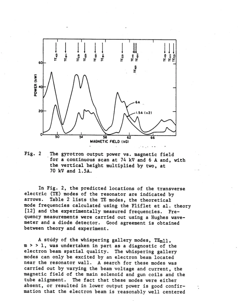
Fig. 2 The gyrotron output power vs. magnetic field for a continuous scan at 74 kV and 6 A and, with the vertical height multiplied by two, at
70 kV and 1.5A.
In Fig. 2, the predicted locations of the transverse electric (TE) modes of the resonator are indicated by arrows. Table 2 lists the TE modes, the theoretical
mode frequencies calculated using the Fliflet et al. theory [12) and the experimentally measured frequencies. Fre-quency measurements were carried out using a Hughes wave-meter and a diode detector. Good agreement is obtained between theory and experiment.
A stddy of the whispering gallery modes, TEmll, m > > 1, was undertaken in part as a diagnostic of the electron beam spatial. quality. The whispering gallery modes can only be excited by an electron beam located near the resonator wall. A search for these modes was
carried out by varying the beam voltage and current, the magnetic field of the main solenoid and gun coils and the
tube alignment. The fact that these modes were either absent, or resulted in lower output power is good confir-mation that the electron beam is reasonably well centered
TABLE 2 GYROTRON 1ODES THEORETICAL FREQUENCY (GHz) 128.0 133.0 137.5 140.3 145.1 147.7 156.5 161.4 161.8 162.3 EXPERIMENTAL FREQUENCY (GHz) 128.2 137.5 140.4 145.2 147.2 156.4 161.5 162.3
in the resonator, away from the walls." In general, ex-citation of the whispering-gallery modes may prove to be a useful diagnostic of gyrotron performance.
Near a field of 5.4 T, the gyrotron operating con-ditions were adjusted so as to maximize the output in the TE0 3 1 mode. An output power of 100 kW was achieved at the conditions listed in Table 3. The far field pattern of the radiation emitted from the gyrotron was consistent with that of a TE031 mode. The microwave emission pulse
TABLE 3 100 kW OPERATION VOLTAGE CURRENT EFFICIENCY PULSE LENGTH MODE MAGNETIC FIELD FREQUENCY BANDWIDTH 80 kV 7.5 A 17% 1.1 ps TE031 5.4 T 140.4 GHz <+100 MHz MODE (TE) 421 811 231 031 521 911 331 141 621 10,11
shape was monitored using a diode detector. Wavemeter measurements indicated single mode emission in the TE031 mode at 140.4 GHz. An upper limit on the emission band-width of +100 MHz is imposed by the wavemeter data, the
limit being set by the finite 0 of the wavemeter. The experimental value of overall efficiency, 17%, is somewhat less than the theoretical value of 30%. Higher efficiency, up to 21%, was achieved in operation at lower beam currents,
between 2 and 4 A.
Discussion and Conclusions
We report the operation of a 100 kW, 140 GHz pulsed gyrotron.operating in single mode emission. To our know-ledge, this is the first operation of a high power gyrotron at a frequency exceeding 100 GHz. In fact, operation in the electron cyclotron maser mode has previously resulted in emission at higher frequency and power levels [ref. 19 and references therein], but only with relativistic beam energies, high currents, rather broad emission bandwidths and low efficiency. To our knowledge, the present experi-ments are also the first operation of a high power gyrotron at a magnetic field as high as 7.OT.
The present results represent a first investigation of the operating characteristics of this gyrotron. By modifying the resonator and undertaking other changes, we hope to eventually improve the gyrotron performance and
output power. The operation of the electron gun has proven to be very satisfactory. The electron gun has produced a beam of up to 600 kW of beam power. That beam has been transmitted from the gun through the resonator and to the collector, through a magnetic mirror ratio of 25. Although the beam quality has not been directly measured, the beam quality must be reasonably good in order to produce high output power radiation. Therefore, the electron gun repre-sents -an important advance in the design of magnetron in-jection guns for high power, high frequency gyrotrons.
In the present experiments, we have chosen to locate the electron beam at the second radial maximum of the cavity RF field. As previously noted, this beam location significantly impacts both the electron gun design and the resonator design. Future gyrotrons operating in the high power, high frequency regime are likely to also require operation with an electron beam of relatively large
diameter. Experience gained in operation of the present gyrotron with a larger diameter electron beam should prove useful in the design of electron guns and resonators for future high power, high frequency gyrotrons.
Although the present experiments have been carried out in short pulse operation, the gyrotron has been de-signed to be capable of an upgrade to long pulse or even cw operation. Such an upgrade would require significant changes in the tube design to provide, for example, a large collector area and cooling in many parts of the tube. However, the present design, in principle, should be capable of high power operation.
The present experiment demonstrates that high power, single mode operation can be achieved at very high fre-quencies with gyrotrons. Based on these results, we be-lieve that operation can be further extended to higher power and higher frequency. Such gyrotrons are likely to prove useful in the heating of magnetically confined plasmas.
Acknowledgements
This research was supported by the U.S. Department of Energy, Office of Fusion Energy, under contract number DE-AC02-78ET-51013. The M.I.T. Plasma Fusion Center is
supported by the Department of Energy. The National Magnet Laboratory is supported by the National Science Foundation.
The authors wish to thank D. Stone, K. Felch, H. Jory and the Varian Gyrotron Engineering Group for their effort on the electron gun. We also wish to thank C. Chase for help with many aspects of this project and .R. Weggel, M. Leupold, L. Rubin and D.B. Montgomery for assistance in magnet de-sign and operation. We thank D. Cohn, R. Davidson, B. Lax, P. Woskoboinikow, K.J. Button, M. Afsar, C.M. Loring,
M. Read, K.R. Chu, A. Fliflet and M. Caplan for very help-ful discussions and suggestions.
References
1. V.A. Flyagin, A.V. Gaponov, M.I. Petelin and V.K.
Yulpatov, IEEE Trans. Microwave Theory and Tech. MTT-25 (1977) 514.
2. H. Jory, S. Evans, J. Moran, J. Shively, D. Stone and G. Thomas, IEDM Technical Digest 12.1 (1980) 304. 3. M.E. Read, R.M. Gilgenbach, R.F. Lucey, Jr., K.R. Chu,
A.T. Drobot and V.L. Granatstein, IEEE Trans. Micro-wave Theory and Tech. MTT-28 (1980) 875.
4. G. Mourier, Ph. Boulanger, P. Charbit, G. Faillon, A. Herscovici and E. Kaurmerer, Sixth Intl. Conf. on Infrared and Millimeter Waves, Conference Digest, IEEE Catalog No. 81CH1645-1 MTT (1981).
5. A.A. Andronov, V.A. Flyagin, A.V. Gaponov, A.L.
God'denberg, M.I. Petelin, V.G. Usov and V.K. Yulpatov, Infrared Physics 18 (1978) 385.
6. H. Jory, Sixth Intl. Conf. on Infrared and Millimeter Waves, Miami (1981).
7. J.J. Tancredi, Sixth Intl. Conf. on Infrared and Millimeter Waves, Miami (1981).
8. A.V.-Gaponov, V.A. Flyagin, A.L. GoI'denberg, G.S. Nusinovich, Sh. E. Tsimring, V.G. Usov and S.N. Vlasov, Int. J. Electronics 51 (1981) 277.
9. S. M. Wolfe, D.R. Cohn, R.J. Temkin, and K.E. Kreischer, Nuclear Fusion 19 (1979) 389.
10. S.N. Vlasov, G.M. Zhislin, I.M. Orlova, M.I. Petelin and G.G. Rogacheva, Radiophys. and Quantum Electron 12 No. 8 (1969) 972.
11. R.J. Temkin, Intl. J. Infrared and Millimeter Waves 2 (1981) 629.
12. A.W. Fliflet and M.E. Read, Intl. J. Electronics 51, (1981) 475.
13. G.S. Nusinovich and R.E. Erm, Elektronnaya Tekhnika, Ser. 1, Elektronika SV Ch, No. 2 (1972) 55.
14. K.R. Chu, M.E. Read and A.K. Ganguly, IEEE Trans. Microwave Theory Tech. MTT-28 (1980) 318.
15. K.E. Kreischer and R.J. Temkin, Int. J. Infrared and Millimeter Waves, 1 (1980) 195.
16. K.E. Kreischer and R.J. Temkin, Int. J. Infrared and Millimeter Waves 2'(1981) 175.
17. M.N. Afsar and K.J. Button, Intl. J. Infrared and Millimeter Waves, 2 (1981) 1029.
18. F.B. Foote, D.T. Hodges, and H.B. Dyson, Intl. J. Infrared and Millimeter Waves, 2 (1981) 773.
19. R.E. Shefer and G. Bekefi, Intl. J. Electronics 51 (1981) 569.