Doped LiFePO
4Cathodes for High Power Density Lithium Ion
Batteries
by
Jason T. Bloking
B.S., Materials Science and Engineering Lehigh University, 2000
Submitted to the Department of Materials Science and Engineering in Partial Fulfillment of the Requirements for the Degree of
Master of Science in Materials Science and Engineering At the
Massachusetts Institute of Technology February 2003
© 2003 Massachusetts Institute of Technology All Diahtc R•eprved
MASSACHUSETTS NSTITUTE
OF TECHNOLOGY
JAN 0
7 200Eq
LIBRARIES
Signature of Author... ..p.e... M•• r
Department of Ma s Scienc and En i ering January 31, 2003
Certified by ... ...-... :-1... •. .. . Yet-Mi Chiang kyocera Professor of Ceramics Thesis Supervisor
Accepted by ... .. ... Harry L. Tuller... Professor of Ceramics and Electronic Materials Chair, Departmental Committee on Graduate Students
Doped LiFePO
4Cathodes for High Power Density Lithium Ion
Batteries
by Jason T. Bloking
Submitted to the Department of Materials Science and Engineering on January 31, 2003 in Partial Fulfillment of the Requirements for the Degree of Master of Science in Materials Science and Engineering
ABSTRACT
Olivine LiFePO4 has received much attention recently as a promising storage compound
for cathodes in lithium ion batteries. It has an energy density similar to that of LiCoO2, the current industry standard for cathode materials in lithium ion batteries, but with a lower raw materials cost and an increased level of safety. An inherent limitation of LiFePO4 acknowledged by researchers studying this material is that its low intrinsic electronic conductivity limits its applicability in commercial systems.
Through a doping process, however, its electrochemical performance at high current rates can be improved to levels above that of commercially available lithium batteries. The increase in performance is brought about by a concurrent increase in the electronic
conductivity and a reduction of the final particle size. The experimental data suggest that cells formulated with this doped cathode material may produce power densities high enough for consideration as a future battery system for hybrid electric vehicles and other
1. Background Information
1.1 Basic Principles of Battery Systems
In the most basic sense, a battery is a device that converts stored chemical energy into electrical energy through a spontaneous chemical reaction. The reaction occurring in a cell is an oxidation-reduction reaction. One species in the cell oxidizes, thereby giving up the electron used to reduce the other species in the cell. In the charged state, the redox reaction is prevented from occurring by physically separating the oxidizable species from the reducible species with an electronically insulating material. When the two species are electrically connected through an external circuit, the reaction proceeds spontaneously
and the electrons flowing through the external circuit provide a current that can be used to power a resistive load.
A battery is composed of a cathode, an anode, and an electronically insulating but ionically conductive electrolyte. The cathode is the species that undergoes reduction during the discharge of the battery, and the anode is the species that undergoes oxidation. Thus, during discharge, electrons flow externally from anode to cathode. Since electrons are flowing away from the anode, it is therefore at a negative electrical potential when compared to the cathode, and is therefore described as the negative electrode. The cathode is thereby referred to as the positive electrode.
There are two types of battery systems: primary and secondary. Primary batteries are those where the chemical reaction is irreversible, and therefore cannot be recharged by forcing the chem'cal reaction to proceed in the opposite direction. On the other hand, secondary battery systems are rechargeable. By supplying an electrical current to move electrons from cathode to anode, the chemical reaction is reversed and the battery is
"recharged." The lith.um batteries used in portable electronics applications such as mobile phones and laptop computers are secondary battery systems.
In a lithium battery, the anode and cathode are separated by a lithium ion conductive electrolyte, usually either an organic solvent or cosolvent mixed with a soluble lithium salt, or a solid polymer material that provides adequate ionic conductivity. The most common commercial anode material is carbon, which can alloy with lithium to form the compound LiC6. The most commonly used cathode material in presently available commercial batteries is LiCoO2. A common organic electrolyte system is a mixture of ethylene carbonate with either diethyl carbonate or dimethyl carbonate with I M of a dissolved lithium salt, often LiPF6. A diagram of a discharging lithium ion cell is displayed in Figure 1. Reistive Load C 0 C Intercalation Anode (carbon) Electrolyte Solution (LiPF6, LiBF4 mi EC,DMC.PC) Intercalation Cathode (LiCoO2)
Fig. 1 - Schematic diagram of a discharging lithium ion battery with an intercalation cathode on the right and carbon as the anode.
In the charged state, the lithium atoms are located at the anode, and upon discharge flow through the electrolyte to the cathode, accompanied by a simultaneous flow of electrons through the external circuit. The reaction occurring at the anode during discharge is then:
LiC6(), - 6C,,, + 1.i + e- (1)
At the cathode, the lithium is intercalated between the layers of the cobalt oxide structure, along with a reduction of the cobalt in the structure from the 4+ oxidation state to the 3+ oxidation state, according to the following reaction:
Li+ + LiCo Co4 O
4,4,, + e- - 2Li+Co3O2(s) (2)
The overall reaction occurring in the cell is the sum of these two reactions:
LiC6(,, + LiCo3+Co4+O4(s) -- 6C(,, + 2Li'Co+O,(,) (3)
The composition above for the "delithiated" form of LiCoO2 is given because LixCoO2 undergoes phase changes for delithiation beyond approximately x = 0.5. For LiFePO4,
the overall reaction using carbon as the anode, would be:
LiC6(s) + FePO4(,,) -4 6C(,,, + Li+Fe2+PO4(,, (4)
The Gibbs free energy of this chemical reaction determines the voltage provided by the cell operating on this oxidation-reduction couple. The discharge of the cell by the above reaction proceeds due to the equilibration of the electrochemical potential at the cathode and anode. The electrochemical potential is the sum of the electrical and chemical potentials:
where pi is the chemical potential of species i, zi is the effective charge on the species, F is Faraday's constant (96,472 C) and 0 is the electrical potential.
By equating the electrochemical potentials at the cathode and anode, an equation relating the potential difference between anode and cathode, the cell voltage, to the free energy of the chemical reaction is obtained. This is the Nernst equation:
I
kg'-#0.)_
AGO(6)
zF z,F
1.2 Metrics of Battery Systems
There are a variety of metrics that are used to compare battery systems to one another, and to determine which batteries are better suited for certain applications. One fundamental property is the energy density, or how much energy the battery can store per unit weight or volume. The energy density of a battery is most often presented in units of Wh/kg or Wh/L, depending on which metric is more desirable.
The energy density of a battery is given by the product of the charge capacity and the voltage of the cell. The capacity is the amount of charge stored or removed during charge or discharge of the battery. In a plot of the voltage of a cell versus the capacity of the cell, the energy density is the area under the curve. The capacity is often expressed gravimetrically in units of Ah/kg. The capacity of a lithium battery is determined by how much lithium can be stored in the electrode materials and reversibly removed during cycling.
Each electrode material has a theoretical capacity and a theoretical energy density, assuming that all the lithium present in the lithiated form is removed. For example, with
LiFePO4, the theoretical capacity is 170 mAh/g, which corresponds to the complete
removal of all the lithium atoms, resulting in a composition of FePO4.
In a practical battery system, there are two electrodes, each of which has a
theoretical capacity. The total capacity and energy density of the battery are then limited by the electrode material of lower capacity. A balanced cell, where the amount of lithium capable of being stored in the cathode is matched to that capable of being stored in the anode, provides for the most charge capacity with the least amount of cell weight. In commercial lithium batteries, the cell is made cathode-limited, to avoid the formation of lithium dendrites at the anode during cycling which can result in short-circuiting of the cell.
Another desirable property of batteries is that they provide high levels of current where required, such as in electric vehicles or load leveling systems. The power density is the property used to describe the high-current capabilities of the system. The power density of the cell is given by the ratio of the energy density of the system and the discharge time. A system with a large power density is capable of providing significant amounts of energy in a short period. The units used are often W/kg.
The energy accessible in a battery is a function of the current. This is because a battery is a kinetic device, relying on time-dependent properties such as ion diffusion and electronic conduction. As the current to or from a battery is increased, the rate of these processes must increase to prevent local charge imbalances. As the currents are
increased, these processes are gradually unable to keep up with the external requirements and some lithium is unable to undergo the movement from anode to cathode on
overall energy density will suffer. This reduction of the voltage due to time-dependent properties like diffusion is termed polarization. Therefore, at higher currents, the energy that the battery is capable of supplying is decreased. This is a key trade-off in battery engineering. This trade-off is best exhibited through a Ragone plot, which plots power density versus the energy density on a logarithmic scale. A Ragone plot is shown in Fig. 2 below. As the power density is increased by drawing a higher current from the battery, the available energy density is decreased.
100000 10000 1000 100 10 1 1 10 100 1000 Energy Density (Wh/kg)
Fig. 2 - Ragone plot showing the trade-off between power density and current density.
1.3 Lithium Battery Cathode Materials
The discovery of layered materials that could successfully intercalate lithium into their structures and release it reversibly sparked an increased amount of research into lithium batteries.1,2 The first successful secondary, or "rechargeable", lithium battery utilized lithium as an anode and the intercalation material LixTiS2as the cathode. It
operated at a voltage of 0.8 V and had a theoretical energy density of 480 Wh/kg.3
However, the use of lithium metal as the anode material proposed several problems. Lithium metal deposited on the anode during charging could only be partially removed during discharge and thus the capacity of the cell would fade with extended cycling.3 In addition to this decrease in energy over time, there are safety issues associated with using lithium metal, such as its reactivity with water.3 The problems associated with lithium metal have been addressed through its replacement with carbon as the anode material, which intercalates lithium at about 0.3 V versus lithium metal, without much of the safety issues.4 This has lead to the commercialization of lithium ion batteries using two
intercalation materials as electrodes, shuttling the lithium back and forth between the layers of the materials, and has hence been named, the "rocking chair battery."6
It was discovered by Mizushima et al.7 that LiCoO2, based on the oxygen anion as opposed to the sulfur anion of titanium disulfide, would lead to higher voltages and therefore higher energy densities. As a result, research was performed into various oxide layer materials. Several candidates for cathodes came from this research, such as Li1.
xCoO27 9, LixMn20410-12, and Li1l.NiO213. These materials all operated on oxidation-reduction couples that produced higher voltages for discharging, thus leading to higher energy density batteries. The theoretical voltages and energy densities of these
TABLE I - Properties of Several High-Voltage Oxide Cathodes
Material Average Voltage vs. Specific Capacity Energy Density
Li (mAh/g)* (Wh/kg)*
Lil-xCoO2 3.9 137 534
Lil.xNiO2 3.8 220 836
Lit.xMn204 4.0
119
476Li .-xFePO4 3.5 150 518
* - calculations are based on a maximum delithiation of x = 0.5 in LilxCoO2, x = 0.8 in Lil-xNiO2 and Li1.
xMn20 4," and x = 0.88 in Lil.-FePO4
Each of these materials has some inherent drawbacks associated with them. For example, Li.-xMn204 has a low practical capacity when used in an actual battery
application.'5 Li.-xNiO
2 is currently used in some battery applications, although it has
safety problems associated with it in its delithiated form.'6 Practically, Li
1-xNiO 2 is not
delithiated past x = 0.8. Lil-xCoO2 undergoes oxygen evolution upon delithiation past x =
0.55,17 but the high voltage associated with the Co3 /Co4' redox couple provides a large
enough energy density to allow practical use in a battery. This material provides the current state of the art for lithium ion batteries. Sony made the first LiCoO2-based
lithium ion battery using a carbon anode (the Lithium Ion Cell) in 1990 and still produces many of those in use today.'8
1.4 Lithium Iron Phosphate
During the 1990s, Goodenough proposed that other materials, based not on the oxygen anion, but on a polyanion network could be used as battery cathodes.'9 The use of materials based on these tetrahedral polyanion structural units (X04)' , n where X is one of
P, S, As, Mo, or W, was predicated on the suspicion that by adding these covalently bonded structures, the redox potential of the transition metal couple in the structure would be shifted to higher energies, thus yielding higher voltages and higher energy
densities.20
,'2 In addition to this, the more "open" structure adopted by these polyanionic materials would facilitate lithium diffusion in the cathode.20
Lithium iron phosphate has an energy density and a voltage similar to LiCoO2, without the toxicity and the safety issues described earlier. There are some drawbacks with LiFePO4, however, such as its inability to provide a high discharge capacity at specific currents above 10 mA/g. This is believed to be the result of an inherently low electronic conductivity.
Research sparked from this original publication included work on such compounds as LixMPO4 (M = Mn, Fe, Co)
22-24 , LixFe2(XO
4)3 (X = P, S)25-26, LiFe(P207),21 and Fe4(P207)3.21 Of these compounds, LiFePO4 has shown the best properties, operating at a voltage of 3.45 V vs. lithium and having a theoretical energy density of 587 Wh/kg. A typical charge-discharge plot at low current is shown in Fig.
3.27
The flat discharge profile seen in the discharge plot is indicative of a two-phase reaction. The discharge reaction proceeds by nucleating LiFePO4 in the FePO4 material, and the two phases are in equilibrium throughout the discharge process, until all the FePO4 has been lithiated to LiFePO4. With the two phases in equilibrium, the chemical potential of lithium throughout the cathode particles is pinned to a specific value. This pinning of the chemical potential is what gives the single value for the voltage throughout the charge and discharge process.
Since the initial discovery of its lithium intercalation properties, much research has been performed to examine its diffusion characteristics28, its cycling behavior29.30
4
3 ao as-2
o01
n0
20
40
60
80 100 120 140 160
Capac
i ty (nAh/g)
Fig. 3 - Low current test of LiFePO4 vs. Li metal showing flat charge and
discharge plateau. This test was conducted at room temperature. From Yamada et al.27
The crystal structure of LiFePO4 is orthorhombic with the space group Pmnb. A
diagram of this structure is shown in Fig. 4. The oxygen ions form a distorted hexagonal close-packed array with the phosphorus atoms in one-eighth of the tetrahedral sites and lithium and iron in total filling one-half of the octahedral sites. The lithium and iron atoms are ordered onto alternating a-c planes in the structure. The LiO6 octahedra are
distorted and share two of their edges with adjacent Li06 octahedra, forming
one-dimensional chains running along the c-axis. The FeO6 octahedra share corners with
adjacent FeO6 octahedra in the other planes forming a 2-dimensional network of corner-sharing iron octahedra. A table showing the various connectivities in the structure is given in Table II.
12 SIst-3rd -~~ _
-C0thobe:
LiFePO
P4:Abode:Li
betal
O.
12niA/y Ist-3rd.PCMCl1MliPF.
"
/I iPITS
C
b
Fig. 4 - a) Ball and stick model of the LiFePO4 structure. b) Polyhedral view of the same structure showing connectivity of Li octahedra in one-dimensional rows and corner-sharing of iron octahedra in a-c plane.
TABLE II - Connectivity of Polyhedra in LiFePO4 (how polyhedron 1 connects to 2)
Polyhedn2 Fe06 Li06 P0
4
Polyhedon I
FeO6 4 corners shared 3 corners shared 4 corners shared with with 4 Fe06 with 4 Li06, 2 edges 4 P04, 1 edge shared
shared with 2 LiO6 with 1 P04
LiO6 4 corners shared 2 edges shared with 2 corners shared with with 4 FeO6, 2 edges 2 LiO6 2 PO4, 2 edges shared
shared with 2 FeO6 with 2 P04
P04 3 corners shared 1 corner shared with No connection
with 3 FeO6, 1 edge 2 LiO6, 2 edges shared with 1 FeO6 shared with 2 LiO6
It is widely accepted that LiFePO4 is an electronic insulator.32,33 Compared to LiCoO2, which has an electronic conductivity at room temperature of 10-3 S/cm34 and
LiMn204, which has an electronic conductivity at room temperature of 10-5 S/cm35, the
10-9 S/cm3 6 conductivity of undoped LiFePO
4 is quite low. This can result in a problem during cycling, as an adequate level of electronic conductivity is necessary to allow electrons to flow through the cathode particles and reduce the Fe3+ upon discharge. Thus, the poor conductivity in LiFePO4 would be expected to adversely affect the rate
capability and power density of a battery formulated with this material, by limiting its use at higher current rates.
There have been many attempts to circumvent this problem. Research has been performed whereby a conductive additive, mainly carbon, has been added in order to increase the rate capability. The various methods employed involved reaction with carbon on a fine scale33"37, reaction with sugar3, and using metal nanoparticles in a
sol-gel reaction.39 A problem with using these conductive additives is that it necessitates an
extra step in the electrode production process, increasing the amount of time and cost involved in the electrode formulation.
1.5 Electronic Conduction in Ceramics
Electronic conductivity can be due to two charge carriers: holes and electrons. The electronic conductivity is given by:
a = nep + peuh (7)
where n and p are the concentrations of electrons and holes, respectively, e is the electronic charge, and pe and ph are the electron and hole mobilities, respectively.
LiFePO4 appears to be a semiconductor with a thermally activated conductivity.36
A way to extrinsically increase the electronic conductivity of a semiconductor, is to increase the number of electronic carriers, either electrons or holes, through doping the semiconductor with other atoms.
In semiconductors and insulators, it is possible to change the number of electronic carriers through the introduction of ionic point defects such as substitutional solutes, interstitials, and vacancies. The charge imbalance created by introducing a point defect
must be compensated in order to maintain an overall charge balance. In ionic
compounds, charge compensation of aliovalent solutes can come in two ways: electronic or ionic compensation.
In electronic compensation, charge neutrality of the solute is due to oppositely charged electronic carriers. An example of electronic compensation is seen in Fel-•O. Iron oxide is rarely stoichiometric except at low oxygen partial pressures, so there are always some thermodynamically stable iron vacancies present at atmospheric conditions. The charge imbalance created by the iron vacancies requires the introduction of some positive charges in order to maintain charge neutrality in the structure. The defect incorporation reaction in Krdger-Vink notation is:
V,+ 2Fe,--V, + 2Fe, (8)
Since the number of holes is increased, a p-type conductivity would be expected. Using the same material, Fel,-O, a mechanism of ionic compensation can be worked out as well. Instead of oxidizing some of the iron atoms to a 3+ oxidation state, some oxygen vacancies with an effective positive charge could be created to balance the charge. This would not produc:e any excess electronic charge carriers and it would not be expected that the electronic conductivity of the material would increase as it would be expected given electronic compensation.
In LiFePO4, both electronic and ionic compensation mechanisms are possible.
Considering a substitutional defect whereby a dopant atom of higher valence state is substituted for lithium in the structure, the electronic compensation would go as:
This would result in an increase in the n-type electronic conduction for the material. Incorporation reactions for several possible ionic compensation mechanisms are shown below:
Li,_-,MxFePO4 -- xML + (1- 2x)Li'. + xV. + Fe', + P, + 40o + xLi - phase (10a)
Li+-xMxFePO, xM + (1 --x)L +X VF, + 1-x Fe,+P +400 +Fe-phase (10b)
2 2 2
Li4,M-FePO4 - xML + (1- x)Lit + Fe + + 1- +400 - phase (c)
Li-_,MFePO, + ,0 -- xML + (1- x)Lix. + Fex, + Pe + 40o + -07 (10d)
In equations 10a through 10d, the Li-phase at the end of the equation describes a second phase that contains x moles of lithium for every mole of LiFePO4. This could be
an oxide or some other second phase compound, and the equation would have to be modified to be mass and site balanced according to what new phase was created.
On first examination, it would appear that the compensation mechanisms in equations 10a through 10d would not result in an increase or decrease in any of the electronic carriers. However, other defect equilibria are maintained between ionic defects and electronic carriers in the system. For example, the iron vacancies in Fe.-xO are a native defect, and the concentration of holes in the material depends on the
concentration of iron vacancies. If the concentration of iron vacancies were decreased by some external means, an increase in the concentration of holes in the material would be expected according to Le Chatelier's principle. An iron vacancy defect equilibrium reaction is shown below in Eq. 11:
The equilibrium constant for this reaction given by Eq. 12:
K =
V ]p
2(12)
Since p, the concentration of holes, and [V,
i
are inversely related, when theconcentration of iron vacancies decreases, the equilibrium causes the number of holes to increase, according to Eq. 12.
By similar relationships, the concentration of electronic carriers in LiFePO4 will
be changed when the concentration of ionic vacancies is changed as above. For example, in stoichiometric LiFePO4, an iron vacancy created in the structure will require
compensation by two holes. However, if some of that compensation now comes from the substitutional dopant for Li, fewer holes are required to electronically compensate, and the conductivity would become less p-type and more n-type.
Whether a material is a p-type conductor or an n-type conductor depends on the dominant mobile carrier. In order to determine experimentally whether a material is a p-type or n-p-type conductor, a few tests can be conducted. One such test is to perform a Hall effect measurement, whereby the material is placed in a magnetic field, and a known current is applied. This causes the dominant electronic carrier (electrons or holes) to migrate towards one side of the material, generating a voltage across the sample. By measuring this voltage and noting its sign with respect to the magnetic field applied, the dominant carrier type can be determined.
Another way is to perform a test of the Seebeck effect. The Seebeck effect is the generation of a space-charge voltage from the separation of carriers due to an applied temperature gradient ac:oss the material. The direction of this induced potential gradient
in relation to the direction of the t•h-.mnal gradient shows if the material is p-type or n-type.
Through an analysis of the defect chemistry of the material and several
experiments such as DC conductivity, Hall, and Seebeck measurements, the mechanism
by which the electronic conductivity is increased can be determined.
2. Electronic Conductivity Experiments 2.1 Experimental Procedures
Doped LiFePO4 powders were synthesizedt by first mixing stoichiometric
amounts of lithium carbonate (99.999%, Alfa Aesar, Ward Hill, MA, USA), iron oxalate dihydrate (99.99%, Aldrich Chemical Co., Milwaukee, WI, USA), ammonium
dihydrogen phosphate (99.998%, Alfa Aesar, Ward Hill, MA), and a transition-metal salt. Several transition-metal sources were used in the synthesis. The sources used were zirconium ethoxide (Reagant grade, Alfa Aesar, Ward Hill, MA, USA), niobium phenoxide (Reagant grade, Alfa Aesar, Ward Hill, MA, USA), magnesium oxalate dihydrate (Reagant grade, Alfa Aesar, Ward Hill, MA, USA), titanium methoxide (Reagant grade, Alfa Aesar, Ward Hill, MA, USA), manganese methoxide (Reagant grade, Alfa Aesar, Ward Hill, MA, USA), aluminum ethoxide (Reagant grade, Alfa Aesar, Ward Hill, MA, USA), iron(IH) ethoxide (Reagant grade, Alfa Aesar, Ward Hill, MA, USA), tungsten ethoxide (Reagant grade, Alfa Aesar, Ward Hill, MA, USA), and tantalum ethoxide (Reagant grade, Alfa Aesar, Ward Hill, MA, USA).
t Note: Powder synthesis, X-ray diffraction, TEM observation, and BET surface area measurements performed by Dr. Sung-Yoon Chung, MIT
These powders were put in a porcelain jar along with acetone and zirconia milling media and ball-milled for 24 hours. The powder mixture was then removed from the jar and dried in air at a slightly elevated temperature for about 2 hours. The dried powder mixture was ground in a mortar and pestle and then stored in an argon-filled dry box for later use.
About 5 g of the powder mixture was placed in an alumina boat inside a
temperature tube furnace. The tube was sealed and then purged for one hour with high-purity argon (99.999%, BOC Gases, Murray Hill, NJ, USA) flowing at about 400 ccm. The powder mixture was calcined in the tube furnace at a temperature of 350'C for 10
hours. The calcined powder was removed from the tube, reground in a mortar and pestle, and placed back in the furnace for a final heat treatment at a temperature between 600'C and 8500C. After the final heat treatment, the powder was removed, ground a final time
with a mortar and pestle, and then returned to the argon dry box for storage until further testing.
X-ray diffraction was performed on the heat-treated powders to determine their phase content and phase purity. XRD was performed with a Rigaku RU-300 x-ray diffractometer (Rigaku Co., Tokyo, Japan) with Cu-Ka radiation. The powders were also analyzed using transmission electron microscopy using a JEOL-2000FX TEM (JEOL Inc., Tokyo, Japan) operating at 200 kV accelerating voltage to observe the powder size, morphology, and also to determine if there was a surface phase on the powder particles.
Pellets were pressed from the calcined powder and sintered at 6000C to 8500C
along with the powder. These pellets were then scraped to remove a surface layer and then qualitatively tested using a Fluke multimeter to determine if they were electronically
conductive. Conductive pellets consistently had a resistance between the two point contacts of approximately 30 kL to a few ML. Pellets that were not conductive had a resistance that was above the 40 MO limit of the multimeter.
These pellets were also polished down to a thickness of approximately 300 tLm and were sputtered with four gold electrodes for four-point DC conductivity
measurements. The DC conductivity measurements were performed with a Bio-Rad Hall Effect Measurement System HL 5500 PC (Bio-Rad, Hercules, CA, USA). The
measurements were done at several temperatures ranging from -50'C to 150'C to determine the temperature dependence of the electronic conductivity.
Qualitative measurements of the Seebeck effect were performed to determine the dominant carrier type in the pellets. The pellet was placed on its side on a hot plate and the potential difference between the surface in contact with the hot plate and the surface in contact .vith the air was measured. A diagram of the setup for this measurement is shown in Figure 5.
T1>T2
Negative lead
i
AV
Positive lead
Fig. 5 - Schematic diagram of the qualitative Seebeck coefficient measurement. The sign of the potential difference across the sample determines the majority carrier in the sample.
Small amounts of powder were chemically analyzed for the major elements as well as impurities such as carbon (Luvak, Inc., Boylston, MA, USA). The concentrations of the metals were determined by inductively coupled plasma atomic emission
spectroscopy (ICP-AES) and the carbon content by combustion analysis.
2.2 Results
X-ray diffraction patterns showed the powders with the transition metal substituted for the lithium precursor and heat treated at 6000C and 700"C to be single
phase LiFePO4. These diffraction patterns, along with an undoped LiFePO4 sample, are
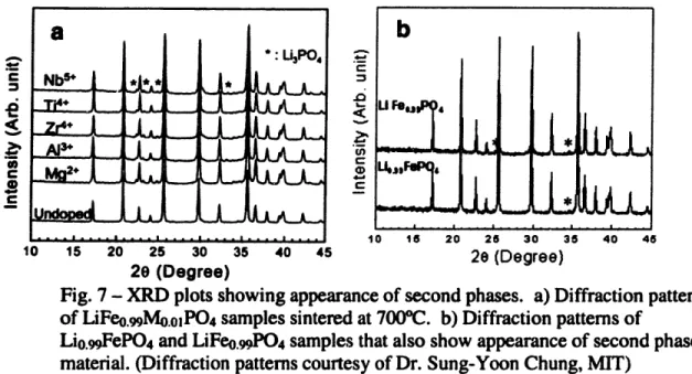
shown in Figure 6 below. Powders heat treated at temperatures above 700"C, however, did show some small amounts of second phase.
Powders synthesized with the transition metal dopant substituting for iron, however, showed small second phase peaks, indicating a material that was not phase
pure. In addition, samples synthesized with 1% lithium or iron deficiency also showed some second phase peaks. These diffraction patterns are shown in Figures 7a and 7b.
Nbrl
ZAILm2+
zl·
0 15 20J
K:
L
LH
tAW 25 30 35 40 45 20 (Degree)Fig. 6 - XRD diffraction patterns of doped powders heat treated at 700PC of the overall composition Lio.99Mo.oFePO4 showing no second phases present.
(Patterns courtesy of Dr. Sung-Yoon Chung, MIT)
10 15 20 25 30 35 40 45
20 (Degree)
10 1s 20 26 30 35 40 46
2e (Degree)
Fig. 7 - XRD plots showing appearance of second phases. a) Diffraction patterns of LiFeo.mMo.oPO4 samples sintered at 7000C. b) Diffraction patterns of
Lio.99FePO4 and LiFeo.9PO4 samples that also show appearance of second phase
material. (Diffraction patterns courtesy of Dr. Sung-Yoon Chung, MIT)
CS .0 U) C 0 C 1( 8 . .: l ..o.
I I
I
b,
UF~I.-
L
ii
I - I li I···l···rl·~··l··ul c···l···rl····j IThe presence of second phase peaks in these diffraction patterns indicates that there is a very narrow solubility window associated with undoped LiFeP0 4. With even one atomic percent deficiency in either the lithium or the iron atoms, the material forms two phases. This limited range of solid solubility for LiFeP04 plays an important role in
determining the conduction mechanism due to the dopant.
TEM images showed the powders to be made up of small particles packed into agglomerates 1 pm and larger. The particle size differed depending on the heat treatment and the dopant added. Lower firing temperatures led to smaller primary particles than higher firing temperatures. The addition of the dopant also led to a smaller particle size as compared to an undoped powder having undergone a similar heat treatment. The dependence of the particle size on the dopant and the firing temperature will be discussed in a later section. TEM images of an undoped powder and a doped powder synthesized at 600"C are shown in Figures 8a and 8b.
Fig. 8 - TEM images of a) undoped and b) doped powders heat treated at 600°C. Powders show same morphology, but undoped shows larger primary particle size than doped. (Images courtesy of Dr. Sung-Yoon Chung, MIT)
Chemical analysis performed on the powders showed almost equal concentrations of lithium, iron, and phosphorus, but also detected the presence of some carbon as well. The source of this carbon is most likely the carbon-containing precursors. The amount of carbon present in the material depends on the heat treatment and the precursors used. The high electronic conductivity of these samples is not due to the presence of carbon, as the amounts of carbon for some of the insulating samples are near or even above those for conductive samples. The carbon content of various heat-treated doped and undoped powders and whether they were insulating or conductive is given in Table 1I.
TABLE Ill - Carbon Contents of Doped and Undoped Powders
Composition Final Heat Treatment Carbon Content Insulating/Conductive
Temperature (wt%)
LiFePO4 7000C 0.342 Insulating
LiFePO4 8000C 0.036 Insulating
Lio.99Zro.olFePO4 6000C 2.21 Conductive
Lio.99Zro.oFePO4 7000C 1.67 Conductive
Lio.99Zro.o1FePO4 800°C 0.854 Conductive
Lio.99Nbo.o1FePO4 600"C 2.42 Conductive
Lio.99Nbo.o1FePO4 800"C 0.588 Conductive
Lio.99Nbo.o1FePO4 7000C 1.48 insulating
LiFeo.99Nbo.olPO4 700°C 1.05 insulating
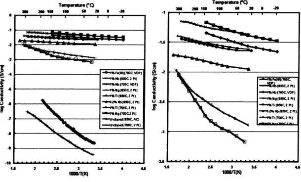
The four-point DC electronic conductivity as a function of temperature was measured using gold blocking electrodes for the undoped and several doped samples. The results are plotted in Figure 9 below. All of the doped materials exhibit an electronic conductivity at least five orders of magnitude higher than the undoped material at room temperature. The conductivity of some of the samples was as high as 10.2 S/cm as compared to the room temperature conductivity of the undoped material of around 10-9
Temperaur QTWW (" Im 2mTIm Ie aua 2MSQ N -ým n uI In m 2 I -2 -3 I, -8 .3 I,
I
U 2. I~ -2 -19 1 - - - - ---I S .6 . . . . A 2.6 3 3. 416 .6 2 2. 3 3 4 4 Ioo(q (K) Moo1(K)Fig. 9 - Temperature dependence of DC electronic conductivity for a) doped and undoped samples and b) doped samples. Doped samples possess at least five orders of magnitude more conductivity and show a weaker temperature dependence.
The conductivity of the undoped material was found to have a larger dependence on temperature than the doped material. This is an aspect of the conductivity that needs to be explained by the conduction mechanism. Another feature apparent from the plot is that the conductivity increase was exhibited using a variety of transition metal dopants. All the dopants used, as long as they go into solid solution, increase the conductivity by several orders of magnitude over the undoped material. It was also found that the conductivity did not predictably vary with the concentration of the dopant added.
The doped pellets were tested in the Seebeck setup and it was determined that all doped compositions were p-type. An undoped pellet was tested as well and was found to be an n-type conductor. This is an important result in determining the conduction
mechanism. S I ~IbI II I IwmuI
---
=oneczrr
-- "%Nb(S5OC2 Pt) ~-4tTI (700C.2 Pt) **.L -d-n% 9(7WC-2 Pt) u lp (8MC.AC) -i pdm(c.z 2Pt) -*"IPNf73SC-VDP) -1ibg( K2 PNJ -- 4%ro mC.2 ft) .. .. .. .. oC. . ) Pt)~ts c~r = m I" in as 5 -"-2.3 Conduction Mechanism
The fact that the doped materials all displayed p-type conductivity limits the possible defects that could be involved in increasing the number of holes. Since the dopants used for lithium result in an effective positive charge for the substitutional defect, an electronic compensation mechanism would result in the creation of an extra electron in the conduction band, which would lead to n-type conduction. Therefore, the increase in the electronic conductivity is not brought about by electronic compensation. Since the effective charge on the substitutional defect is positive, a defect with a negative effective charge must be created for charge compensation. The possible defects that have a negative effective charge in this structure are cation vacancies and oxygen interstitials.
However, many of these defects are unlikely because the free energies required to create these defects are too high. Since the oxygen is in a hexagonal close-packed
arrangement, the energy to create an oxygen interstitial is probably too high, and so this compensation is unlikely. The creation of a phosphorus vacancy would probably also require a high energy, because the phosphorus is covalently bonded to oxygen.
Therefore, it is much more likely that the compensating ionic defect is either lithium or iron vacancies. However, due to secondary defect equilibria in the materiel, the
compensation via lithium or iron vacancies would lead to an increase in the number of electrons in the conduction band. Therefore, the compensation mechanism in this material is not simple, and a different mechanism must be the result of the doping.
One way in which several ceramics become p-type conductors was illustrated previously with the example of Fe,.xO. Iron vacancies are electronically compensated by holes, chemically equivalent to oxidation of some Fe2+to Fe3+. If iron or lithium
vacancies were possible in the LiFePO4 structure, then a similar mechanism could
provide the necessary number of holes to increase the electronic conductivity.
A plausible model must be able to explain all the details that have been seen in the
experiments. These are p-type conductivity, a weak dependence on the type or concentration of the dopant, and a weak dependence on temperature. From all these observed occurrences, the most plausible conduction model is creation of holes to compensate for lithium vacancies, similar to Fel-.O. The purpose of the dopant, then, is to extend the solid solubility regime to allow more vacancies in the LiFePO4 structure
without forcing a phase change, which is seen in the undoped LiFePO4 structure upon
electrochemical introduction of lithium vacancies.
Another experimental detail that lends itself to this model is the ability of the doped LiFePO4 powder to cycle at significantly high rates, up to 50C, as will be seen
later. In order to maintain this high rate capability, the delithiated form, FePO4, must also
possess an adequate electronic conductivity to allow cycling. In the delithiated form, the iron atoms are present in the 3+ oxidation state. With the dopant still present in the delithiated compound, it can be described relative to FePO4 as an interstitial defect, with
an excess positive charge. In order to balance this, an acceptable defect would be the creation of an electron in the conduction band via the reduction on an iron atom in the structure from the 3+ to the 2+ state. This would lead to an n-type conductor in the delithiated state.
To test whether the delithiated doped compound is an n-type or p-type conductor, pellets of doped LiFePO4 were chemically delithiated using n-butyllithium (Alfa Aesar,
performed on these pellets as well by Dr. Sung-Yoon Chung. These pellets did show n-type behavior, supporting the vacancy model for the conduction mechanism.
With this model, the defect incorporation reaction in the LiFePO4 is the same as
that for the FeO compound in Eq. 8. In the delithiated form, the defect incorporation reaction is shown below In Eq. 13:
2Fex, + M ý M" + 2Fe,* (13)
In this reaction, ionization of the reduced Fe2+ adds an electron to the conduction band, increasing the n-type conductivity of the material.
3. Particle Size Experiments 3.1 Experimental Procedures
Powders synthesized according to the descriptions above were analyzed to determine their average particle size. Powders were analyzed using Brunauer, Emmett, and Teller surface area measurements using nitrogen adsorption to determine the surface area. This technique determines the primary particle size, instead of the agg;omerate size.
3.2 Particle Size Results
The particle sizes were dependent on whether the powder was doped or undoped, given an identical heat treatment, according to the specific surface area measurements. Given the same heat treatment, the doped powder had a higher specific surface area, and hence a smaller particle size. It would appear that the addition of the dopant serves to hinder the particle growth in addition to increasing the electronic conductivity. The
specific surface areas and equivalent spherical particle sizes of several doped and undoped powders at various heat treatments are given in Table IV.
TABLE IV - Specific Surface Area and Equivalent Spherical Particle Size of Doped and Undoped Powders
Powder Specific Surface Area Equivalent Spherical
(m2/g) Particle Radius (nnm) LiFePO4, 6000C 9.5 87 LiFePO4, 7000C 3,9 210 Lio.99Zro.otFePO4, 600cC 41.8 20 Lio.99Zro.o1FePO4, 7000C 26.4 31 Lio.99Zro.01FePO4, 7500C 11.6 71
From these results, it would be suspected that the doped material would be able to cycle at higher rates than the normal undoped material. By improving both the electronic conductivity and reducing the particle size, it is expected that the rate capability of the
material should increase. The purpose of the next set of experiments was to determine the cycling capabilities of the doped material.
4. Cycling Experiments
4.1 Experimental Procedures
Both doped and undoped powders were prepared for electrochemical cycling in the following manner. The cathode powders were mixed with Super P carbon (M.M.M. Carbon, Brussels, Belgium) and one of three types of polymer binders. The binders used were polyvinylidene fluoride (PVdF, Alfa Aesar, Ward Hill, MA), Kynar 461 (Atofina Chemicals, Philadelphia, PA, USA), and Kynar Powerflex 2801 (Atofina Chemicals, Philadelphia, PA, USA). The powder, carbon, and polymer were mixed in various proportions usi,ig y-butyrolactone (99.9%, Aldrich Chemical Co., Milwaukee, WI, USA)
as a solvent to dissolve the polymer. The carbon was added to be either 5 or 10 wt% of the solids in the mixture. The polymer binder was always added at a concentration of 11 wt% of the solids. The balance of the solids in the mixture was from the cathode powder.
The three components were weighed out according to the desired proportions inside an argon dry box. The polymer binder was first placed in a 2 mL polypropylene vial with a screw top. The total volume of the solid contents (cathode, carbon, and polymer) was calculated and the y-butyrolactone was added to the polymer binder in order to have 89 volume percent y-butyrolactone and 11 volume percent solids. A /4"
Teflon® ball was added to this vial and the screw top was sealed. The vial was shaken by hand for approximately one minute in order to dissolve the polymer in the solvent.
The vial was then opened and the carbon and cathode powder were added. The vial was sealed again and removed from the argon dry box. The vial was then shaken for 5 minutes using an amalgamator to shake the vial rapidly along its long axis. During this time, a substrate for the slurry was prepared using aluminum foil. The foil was taped to the bench and cleaned with ethanol. After the 5-minute mixing was finished, the vial was removed, opened and the slurry was cast onto the foil using a stainless steel stencil, either 254 or 512 pm thick. After casting, the coatings were placed under vacuum overnight to dry the films.
After the films had fully dried, the coatings were pressed between stainless steel plates at a pressure of four metric tons/cm2. Some of the coatings were subjected to a plasticizing treatment involving immersion of the coating in a 15% by volume solution of propylene carbonate in methanol for 10 seconds. The coatings were then dried and pressed between clean Mylar®films at the same pressure as the unplasticized coatings
using steel plates heated to 150C(. After pressing, all the coatings were cut into samples with an area of approximately 1/3 cm2 for testing. After cutting, the samples were
returned to the argon dry box and dried in a furnace inside at approximately 80PC overnight to remove any water absorbed while handling in air.
Electrochemical cells were assembled in Swagelok*-type two-electrode cells using lithium metal foil (Alfa Aesar, Ward Hill, MA) as both the counter and reference electrodes. The cells were assembled in an argon dry box to prevent any moisture from entering the cell. The liquid electrolyte used was a 1:1 by weight mixture of ethylene carbonate (EC) and diethyl carbonate (DEC) with IM LiPF6 as the lithium conductive
salt. The cathode and anode were kept electronically isolated from each other with a polypropylene separator, Celgard® 2500 (Hoechst Celanese Corporation, Charlotte, NC,
USA).
Electrochemical testing was performed using a custom-made battery tester. Cycling was done using galvanostatic techniques, at currents from C/10 up to nearly 100C rate. The voltage limits used for the testing were 2.0 and 4.2 V for the lower and upper voltage limits, respectively. The galvanostatic tests at various rates were also performed at temperatures of 23*C, 3 1C, and 42*C.
4.2 Experimental Results
Several variables were investigated in order to determine their effect on the cycling properties of the material. Those parameters investigated were the primary particle size of the cathode, its electronic conductivity, the amount of carbon conductive additive, the thickness of the electrode, the type of polymer binder used in the positive
electrode coating, and the temperature. By analyzing the effects of these parameters, much about the cycling abilities of doped LiFePO4 can be determined.
4.2.1 Doped vs. Undoped LiFr PO4
An undr ped and doped powder, synthesized in exactly the same way, with a heat treatment at 6000C, were tested galvanostatically at a rate of C/5 to see what the
differences were at slow rates. The discharge curves of the two powders are shown in
Fig. 10. The doped LiFePO4 exhibits a larger discharge capacity at this rate. The
discharge curve at a higher rate of 5C is also shown. The difference between the doped and undoped powder is more apparent at this higher rate. Figure 11 shows the
dependence of the capacity on the discharge rate, in which the improved rate capability of the doped LiFePO4can be seen clearly.
4.5 4
E3.5
2.5 21.5
.%P 0 20 40 60 80 100 120 140 Capacity (mANg)Fig. 10 - Discharge curves of undoped and doped LiFePO4 at a discharge rate of
C/5 and 5C. The discharge capacity of the doped material exceeds 140 mAh/g,
160
140
E 120 --- LiFeP04.OMoc 10o- 1% Zr-UFePO4, 00C 60 t -- - --- ,- --- --- - ~- -- ~---60
40 0 641 -n 0 10 20 30 40 50 60 Dhischarge C RateFig. 11 - Discharge capacity as a function of discharge rate for undoped and
doped material with the same heat treatment, showing the greater rate capability of the doped material.
4.2.2 Particle Size Effects
Undoped powders with different equivalent particle sizes were tested to see what effect decreasing the particle size could have on the undoped material. The undoped powders tested were synthesized at 600"C and 700'C, respectively, and differed in
equivalent spherical particle size by a factor of approximately 2.4. It is expected that the smaller particle size cathode powder would cycle better, given that the electrochemical
discharge was rate-limited by a process occurring in the cathode material and not in another area, such as the liquid electrolyte. This is because there is less distance for the
intercalating lithium to diffuse through during the discharge in order to reach the center of the particle.
40A
The plot of capacity vs. discharge rate for the two undoped powders is shown in Figure 12. The 600(C undoped powder, with the smaller particles, shows an clear discharge plateau even at rates at which the larger particle 700(C sintered sample shows no discharge plateau. 100 90 80 70 5O
40
30 20 10 0 0 5 10 15 20 25 30 35 40 Discharge C RbFig. 12 - Effect of particle size on the rate capabilities of the undoped material. At intermediate rates around 5C, the smaller particle size material exhibits twice as much discharge capacity.
Three doped powders were subjected to three different heat treatments in order to produce powders with three different primary particle sizes. The powders were heat treated at 600(C, 7000C, and 750"C, respectively, leading to the equivalent spherical particle sizes shown in Table IV of 20, 31, and 71 nm. Figure 13 shows the variation of the discharge capacity with rate for the various powders. The powder with the smallest particle size shows the highest rate capability. This nano-sized particle is capable of cycling at rates up to 46C with a capacity of 23 mAh/g.
1 U 140 E 120 100 80
S60
40 20o0
0 10 20 30 40 50 60 Discharge C RateFig. 13 - Variation of particle size in doped powders. The 600(C and 700'C
powders have similar particle sizes, but the 7500( powder has a particle size three times as big.
The discharge curves at various rates for the 20 nm powder are shown in Figure 14. The powder still shows the same characteristic plateau at nearly 3.45 V at slow rates, with a decrease in the discharge capacity at higher and higher rates.
4 3.5
2.5
2.5 1.5 4bb I. -\--
N
--0 20 40 60 80 100 120 140 160 Capacy (mAh)Fig. 14 - Discharge curves for the 20 nm doped powder. The legend gives the rates in Charge Rate/Discharge Rate.
For further analysis, the Ragone plots of power density against the energy density of the cathode are shown in Figure 15 for the three doped powders of different sizes. This shows the large increase in power density for a given energy density that can be obtained by heat treating the powder at a temperature of 600'C instead of 750'C.
- 0.2CIO.2C - 0.9C/0.9C - - 0.9C/1.8C - '0.9C/4.6C - '0.9C19.1C 0.9C/18C - 0.9c/280 0.9C/37C - 0.9C/46C -- 0.9c/55C Sa 0.9C064C L IMMMM09 II I
tt
J1
100000
10000
1000
100o0
,- 1% Zr-LIFePO4, 600OO 0 1% Zr-LIFePO4, 700*C 10 ,i 1% Zr-LiFePO4, 7500C 1 1 10 100 1000Energy Density (WhIkg)
Fig. 15- Ragone plots based on the weight of the cathode alone. The large particle size powder has significantly less power density at the middle energy densities.
From this data, it is apparent that the particle size plays a role in determining the cycling properties of this material. With such a difference among the rate capabilities of the three doped materials that have different particle sizes but very similar electronic conductivities, it would seem that increasing the electronic conductivity of the cathode material is not the sole reason for the improvement of its rate capability during cycling.
4.2.3 Electronic Conductivity Effects
A doped powder sample sintered at 750°C and an undoped powder sample sintered at 600'C have somewhat similar particle sizes, as can be seen by their similar specific surface areas from Table IV. However, these two powders differ by several orders of magnitude in their electronic conductivity. Therefore, these two powders
should provide a good image as to what the effect of increased electronic conductivity is given approximately the same particle size.
The plot of discharge capacity against the discharge rate for these two samples in Figure 16 shows only moderately better discharge properties for the doped and highly conductive powder. As a result, it appears that increasing the electronic conductivity alone does not assure a high rate capability. It is also critical to reduce the particle size of the powder. In addition, the doped powder tested here had a 22% higher specific surface area, which translates to an 18% smaller equivalent spherical particle size. Therefore, some of the observed increase in rate capability is most likely also a result of the slightly smaller particle size.
100 90 so S30
60
10 ~50140 S20 10 0 0 10 20 30 40 50 60 70 Discharge C RateFig. 16 - Demonstration of effect of electronic conductivity of the powder on discharge capacity. The more conductive powder is somewhat better at higher rates.
4.2.4 Electrode Thickness Effects
The thickness of the electrode has been known to affect the discharge properties of a cell. This is because the diffusion of lithium ions through the ionically conductive
liquid electrolyte can be rate-limiting. Therefore, it is possible that if the electrode is thick enough, the discharge process can be limited by the diffusion of the lithium ions through the liquid electrolyte-filled pores in the cathode film.
For a specific comparison, three films were made from the 600'C doped powder that had different thicknesses; one was 44 p. thick, one was 86 pCm thick, and the other was 101 pm thick. All other parameters were identical between the two films. The plot of discharge capacity against the discharge rate for these two samples is shown in Figure
17. At the lower rates, the capacities are approximately the same, but at rates greater than
approximately 5C, the capacity accessible in the thicker sample drops off rapidly. At rates greater than 30C, there is no evidence of a discharge plateau for the thickest
electrode. On the other hand, the thinnest sample is capable of discharging at rates up to
70C at room temperature. Since these samples differ only in the thickness of the cathode
coating, it can be concluded that at a thickness of 100 pmn, the discharge capabilities of the coating are becoming limited by the lithium diffusion through the liquid electrolyte-filled pores in the cathode samples. It is not apparent that by making the coating thinner than 44 pm that the rate capabilities can be increased. There may be another time-dependent transport process that is rate-limiting at the lesser thicknesses, such as lithium absorption through the surface of the cathode material.
140 120 100 8 to0 Eo 20 0 n 0 10 20 30 40 50 60 70 80 Discharge C Rta
Fig. 17 - Discharge capacity as a function of rate for two similar electrodes of much different thicknesses. The thicker electrode sample is most likely
rate-limited by the diffusion of lithium ions through the liquid phase electrolyte.
The drastic difference can be seen in the Ragone plots of the two samples at room temperature in Figure 18, showing the much higher power density of the thinner sample.
100000 10000 1000 . 100 0 10 1 1 10 100 1000
Energy
Density
(Wh/kg)
Fig. 18 - Ragone plot of the thin and thick electrodes. Using electrodes around
50 pm thick seems to be adequate to eliminate the effect of thickness at most rates.
4.2.5 Effect of Carbon Additive
The addition of carbon to the coating provides a highly conductive percolating network in the electrode that facilitates electronic conduction through the composite cathode during the charging and discharging processes. It is also believed that the concentration of high surface area carbon affects the liquid electrolyte penetration as well. Thus, the amount of carbon used can have an effect on the discharge characteristics of the cell.
Samples were tested using Super P carbon in the weight proportions of 5 and 10 wt%. Figure 19 shows the difference in the rate capability between two particular samples. The figure shows that there is a difference between the two samples, where the
sample with more carbon has significantly better rate capabilities than the one with less carbon. However, it should be noted that the doped sample containing 5 wt% carbon did possess better rate capability that an undoped sample with 10 wt% carbon, as can be seen in some of the earlier figures. The added carbon is an inactive material on the cathode side, and so using less in the final formulation will help the overall energy and power density of the cell.
160 140 4C 120 E 80
60
40 20 0 0 10 20 30 40 50 60 Discharge C RateFig. 19 - Effect of using 5 wt% Super P additive versus 10 wt% Super P additive. The sample with more conductive carbon additive cycles more effectively
4.2.6 Effect of Polymer Binder
The effect that the type of polymer binder used had on the rate capability was determined using samples made with two different kinds of Kynar®, a commercial polymer binder made by Atofina Chemicals. Samples made with Kynar 461 and Kynar
2801 were made to test the effects on the cycling properties. The results in terms of rate
The Kynar 461 is polyvinylidene fluoride (PVdF) that is processed to have good properties for a binder for battery electrode coatings. The Kynar 2801 is a copolymer made of both polyvinylidene fluoride and hexafluoropropylene (HFP). From the figure, it seems that the Kynar 2801 sample performs better at rates below approximately 20C, but at rates higher than that, the Kynar 461 sample performs better. As of now, it is unsure why the two samples behave the way they did.
160 140 120 100 8 600 20 0 0.0 10.0 20.0 30.0 40.0 50.0 60.0 70.0 80.0 Discharge C Rate
Fig. 20 - Discharge capacities as a function of rate for samples using two different types of polymer binder, Kynar 461 and Kynar 2801.
4.2.7 Temperature Effects
All cells were cycled at temperatures of 230C, 3 1C, and 42*C to determine if the
rate-limiting step in the discharge was a temperature-dependent process. Most cells showed some degradation after heating up to temperatures around 420C, and especially those that were held there for several days in order to complete testing. Many cells, though, either showed no change in capacity or an increase in capacity with increasing
temperature. The increase in capacity with temperature is consistent with the rate-limiting process in the cell being governed by a diffusion process, such as solid state lithium diffusion or liquid-phase lithium diffusion. However, those cells that exhibited no change in capacity with increasing temperature could be rate-limited by a process that is independent of temperature.
The undoped samples sintered at 700(C did not show a significant temperature dependence when analyzing the discharge capacity against the discharge rate, as is shown in Figure 21. Since it was shown before that the temperature dependence of the
electronic conductivity in the undoped sample was high, this would also suggest that electronic conduction through the cathode particle is not the rate-limiting process.
70 60
5so
I
40 30 20 10 n 0 5 10 15 20 25 30 35 Discharg C RaoeFig. 21 - Lack of temperature dependence in capacity seen in an undoped powder sample.
In some of the doped samples, there appears to be a range of rates at which the capacity of the cell is not temperature-dependent. In Figure 22 below, the data for a
MOM.23-C
=4M~lC00=42C
I
doped sample is shown where this region exists at rates less than 30C. Above this rate, however, the sample shows a definite temperature dependence. By comparing this data for a 44 gpm thick electrode with that of a 101 Ipm electrode in Figure 23, it appears that the diffusion of lithium through the liquid-phase electrolyte is certainly temperature dependent. Therefore, it may be that the rate-limiting step in the 44 pm sample changes from one that is not temperature dependent to liquid-phase electrolyte diffusion.
K.
C,I
I
020
40 60 80 Dicharge C RateFig. 22 - Lack of temperature dependence in capacity seen in lower rates. Temperature dependence at higher rates is likely activated electrolyte diffusion.
100 120
doped sample at a result of thermally
180 140 20 40 0 5 10 15 20 25 30 35 40 45 Dischrge C Rate
Fig. 23 - Evidence of temperature dependence of capacity at all rates for thicker electrode likely cause by thermally activated diffusion through liquid phase electrolyte.
5. Discussion
The data presented above shows that as a result of the transition-metal doping, the electronic conductivity and cycling properties of this promising cathode material have bev;n improved greatly. The addition of the dopant increases the electronic conductivity of the doped powder to at least five orders of magnitude above the level of the undoped powder. This increase is seen over a wide range of dopants with different valences and over a wide range of concentrations, as long as the dopant is soluble in the material.
However, this increase in electronic conductivity is not solely responsible for the excellent cycling properties of the cathode. It has also been shown that the addition of the dopant also suppresses particle growth during the final heat treatment, such that the final particle size given an identical heat treatment is more than four times smaller than in