HAL Id: hal-01888431
https://hal.archives-ouvertes.fr/hal-01888431
Submitted on 5 Oct 2018
HAL is a multi-disciplinary open access
archive for the deposit and dissemination of
sci-entific research documents, whether they are
pub-lished or not. The documents may come from
teaching and research institutions in France or
abroad, or from public or private research centers.
L’archive ouverte pluridisciplinaire HAL, est
destinée au dépôt et à la diffusion de documents
scientifiques de niveau recherche, publiés ou non,
émanant des établissements d’enseignement et de
recherche français ou étrangers, des laboratoires
publics ou privés.
Design and optimization of Heat Integrated Distillation
Column “HIDiC”
Omar Yala, David Rouzineau, Raphaële Théry Hétreux, Michel Meyer
To cite this version:
Omar Yala, David Rouzineau, Raphaële Théry Hétreux, Michel Meyer. Design and optimization of
Heat Integrated Distillation Column “HIDiC”. Computer Aided Chemical Engineering, Elsevier, 2017,
40, pp.1783-1788. �10.1016/B978-0-444-63965-3.50299-3�. �hal-01888431�
OATAO is an open access repository that collects the work of Toulouse
researchers and makes it freely available over the web where possible
Any correspondence concerning this service should be sent
to the repository administrator:
[email protected]
This is an author’s version published in: http://oatao.univ-toulouse.fr/20395
To cite this version:
Yala, Omar
and Rouzineau, David
and Thery-Hetreux, Raphaele
and
Meyer, Michel
Design and optimization of Heat Integrated Distillation
Column “HIDiC”. (2017) Computer Aided Chemical Engineering, 40.
1783-1788. ISSN 1570-7946
Official URL:
https://doi.org/10.1016/B978-0-444-63965-3.50299-3
Design and optimization of Heat Integrated
Distillation Column “HIDiC”
Omar Yala,
aDavid Rouzineau,
aRaphaele Thery-Hetreux,
aMichel Meyer
LGC Laboratoire de Génie Chimique, INPT Institut National Polytechnique de
Toulouse, 4 Allée Emile Monso, Toulouse31030, France.
[email protected] / [email protected]
Abstract
Distillation is the most applied separation technology. However, its major drawback is the low thermodynamic efficiency (typically around 10%). In response to environmental issues that concern energy consumption of distillation columns, HIDiC (heat integrated distillation column) is expected to have a large impact on energy saving. The aim of this study is to optimize the HIDiC sensitive parameters so as to minimize the Total Annual Cost (TAC). For this, a HIDiC simulation model is developed by using commercial software ProSimPlus. GA (Genetic Algorithm) is used to find the optimal HIDiC configuration where multivariable are optimized without initialization. Binary (Benzene/Toluene) separation case is examined. As a result, 7.4 % and 13.9 % TAC reductions are realized in comparison with the reported solutions in previous works.
Keywords: Distillation column, Heat integration, Optimization, Genetic Algorithm,
HIDiC.
1. Introduction
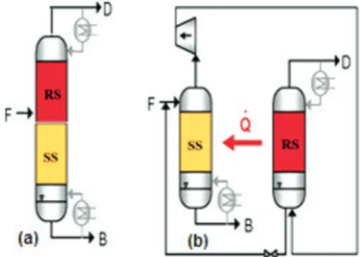
Distillation is a unit operation which is widely used in separation processes. It represents approximately 40% of the total energy of the chemical process industry and more than 50% of the plant operating cost. The major drawback of the distillation column (Figure 1-a) is the low thermodynamic efficiency which is less than 10%. This is due to the temperature difference between reboiler and condenser (Bruinsma et al., 2002). Usually, the energy consumption, capital and operating costs increase as the relative volatility decreases (Kiss and Olujic, 2014). In the literature, a promising solution to reduce the energy consumption is proposed. It is called Heat Integrated Distillation Column (HIDiC) (Figure 1-b). The rectifying section and the stripping section are separated and heat is transferred inside the distillation column from the rectifying to the stripping section. The compressor increases both the operating pressure and the stage temperatures of the rectifying section. As expected, an energy gain was observed in previous research on HIDiC simulation studies (Jansens et al., 2001; Ponce et al., 2015). A 90% energy saving can be reached with binary system like Propylene/Propane with 1.15 relative volatility. In accordance with (Kiss, 2013; Gutierrez-Guerra et al., 2016) conclusions, the best candidates of HIDiC are the mixtures of components with close boiling point. Furthermore, an optimization study of HIDiC schemes using genetic algorithms was achieved (Shahandeh et al., 2014). The separation of benzene and toluene mixture was used as a case study. The variables were compression ratio, number of heat exchangers and heat exchangers location.
Results showed up to 6.60 % and 9.75 % TAC reduction in HIDiC optimization. In this work, some improvements are achieved on HIDiC optimization. A simulation procedure is proposed for the HIDiC design. Then, Genetic Algorithm is used so as to find the optimal heat distribution along the HIDiC while the fitness function is set to be the total annual cost (TAC). The best HIDiC configuration obtained is compared with the reported solutions in a previous work for the same examined case study (Suphanit, 2010; Shahandeh et al., 2014). In this paper, the design-optimization strategy is performed by using the Excel-ProSimPlus interface.
Figure 1: a. Conventional distillation column, b. HIDiC.
2. Simulation and design approach
Based on MESH model calculations, a simulation procedure is proposed for heat integrated distillation columns (Figure 2).
o Step 1: the HIDiC simulation procedure starts with the synthesis of a conventional
column for the given system based upon a classical approach (shortcut approach and adjustment of the distillation column parameters using a ProSim Simulation. o Step 2: Based upon this initial structure, rectifying and stripping section are
decoupled. As the heat transfer technology is based upon a concentric column structure in our experimental pilot, rectifying and stripping sections of the HIDiC configuration are supposed to have the same number of stages. In this first configuration, simulation is performed without any heat transfer between the columns that will enable an efficient heat transfer. The purpose of the simulation is to determine the pressure ratio on the compressor. A minimum temperature approach is fixed to 5K.
o Step 3: A complete HIDiC with full heat integration is carried out. As suggested by
(Suphanit, 2010), the heat duty calculated in the conventional column reboiler (Qreb) is uniformly distributed on the stages (see Equation 1).
(1) Where N is the stage number in each section (rectifying stage 1 and stripping stage N are respectively the condenser and reboiler stages).
o Step 4: In HIDiC, the liquid is evaporated gradually and uniformly along the
stripping section, at the same time, the steam is condensed along the rectifying section. In this step, a maximum amount of energy (QT max=∑Qi max) is determined by gradually increasing the level of heat transfer between the two columns, until there is no more liquid in the stripping column or no more vapour in the rectifying column. The HIDiC design results are the maximum heat (QT max), reboiler and condenser remaining heat duties, the compression ratio that respects the minimum temperature difference constraint and reflux ratio. The utility cost (OPEX), capital cost (CAPEX) and energy saving are evaluated in the end of HIDiC simulation.
o Step 5: In optimization by Genetic Algorithm, a multivariable initialization is not
essential. The exchanged heat profile of the resulting HIDiC configuration is optimized and the method is explained in part 3.
Figure 2: Synthesis procedure for HIDiC.
3. Optimization methodology
A stochastic optimization based upon genetic algorithms is performed to determine the heat exchange (Qi) profiles that will minimize the TAC. The stochastic approach is chosen so as to make the simulation possible by multiplying the variables and the fitness function. HIDiC simulation is based on the Newton-Raphson method while GA is utilized for optimization. Additionally, parameters of genetic algorithm during the optimization are taken from (Shahandeh et al., 2014). To be comparable to the previous works, the calculation parameters presented below are fixed in the script. In the current work, the optimization objective function (TAC) is a combination of capital cost and utility costs. TAC estimation formulation is demonstrated in equation 2.
(2) Here, n =10 years and i = 7 %.
3.1. Estimation of Capital Cost (CC)
HIDiC consists of column shells and sieve trays, a reboiler and a condenser as heat exchangers and a compressor. For each equipment, the installed cost estimates are calculated as given by (Olujic et al., 2006; Douglas, 1988). As used before, the M&S Index value of 1463.2 averaged for process industries in the 1st quarter of 2008 is applied. All constant coefficients for compressor and heat exchangers cost estimation with various types are illustrated by (Olujic et al., 2006). Column diameter is designed at 80 % flooding using Fair correlation. Then, it was assumed that all stages in both sections are sieve tray with 1.5 feet tray spacing. The HIDiC column is constructed as a concentric column. Its cost is then estimated from two-column shells. Due to the large variation in the vapor flow along the column, average diameter of the rectifier and maximum diameter of the stripper is taken into account for economical computations.
Capital cost of column shell is multiplied by a factor of 1.5 to account for construction difficulty. The isentropic efficiency of the compressor is set to 72 %. The value of the overall heat transfer coefficient in the heat panel along the HIDiC column is assumed constant at 1000 W/m2K.
3.2. Estimation of Utility Cost (UC)
The available utilities are electricity, low pressure steam, and cooling water with unit costs of $0.1/ kWh, $13/t, and $0.03/t, respectively. The evaluation of TAC is on the basis of 8000 operating hours per year. Column diameters, CC, UC and TAC are evaluated in the end of HIDiC simulation.
3.3. Case study
Benzene-toluene separation has been previously studied (Suphanit, 2010; Shahandeh et al., 2014). For this reason, the binary equimolar mixture of benzene-toluene was chosen. A feed flow rate of 100 kmol.h-1 is introduced. Feed stream is available at the temperature and pressure conditions of 94 °C and 100 kPa. RK-Soave equation of state has been employed for thermodynamic properties computation. The purity specifications of benzene in the distillate and toluene in the bottom product are both 99.5 % mol. In addition, both the conventional sequence and the HIDiC sequence have the same total number of stages. Similarly, both rectifying and stripping sections have the same number of stages.
4. Results and discussions
In this part, the HIDiC design-optimization results obtained by applying the procedure are presented. Then, they are compared with literature to evaluate the proposed method. The results of HIDiC design without optimization are summarized in Table 1 and they are compared to the conventional distillation column (CDiC). Total stage number of 32 is obtained, that includes 16 stages in the stripping and rectifying columns when the pressure drop for each stage is negligible. 15 stages are thermally integrated considering the condenser in the first stage of rectifying column and the reboiler in the last stage of stripping column. HIDiC reboiler and condenser heat duty are reduced up to 85 % and 51.8 % respectively. The required energy for a compression ratio of 256.7 kPa is 250.4 kW. The maximum heat to be integrated per stage is 99.39 kW and the total exchanged heat is 1490.9 kW. The HIDiC simulation results respecting the simulation procedure with optimization are shown in Figure 3. Then, the optimal heat distribution along the HIDiC obtained by GA is presented in Figure 4. After simulation, the temperature difference results (Figure 5) and the optimized heat distribution allow to determine the heat panel area for each paired trays (Figure 6). Reference work 1 refers to Shahandeh proposal and reference work 2 refers to Suphanit proposal. In this case, the minimum temperature difference between rectifying stage and stripping stage is 8 K. The heat transfer area distribution of the optimized HIDiC as proposed in the reference work 1 is variable and larger near the ends and smaller towards the middle. By contrast, the reference work 2 requires a constant heat panel area of 4.58 m².
Table 1: Simulation results of CDiC and HIDiC design
QreboilerkW QcondenserkW QcompressorkW Reflux ratio PrectifierkPa
CDiC 990 1,198 - 1.79 100
Variables HIDiC by GA Ref. work 1 Diff. % Ref. work 2 Diff. %
Number of heat panel 15 16 - 16 -
Heat panel location in stripper 1:15 1:16 - 1:16 -
Heat panel location in rectifier 2:16 1:16 - 1:16 -
Pressure of the rectifier (kPa) 256.7 256.7 - 294 - 12.69
Total heat integration (kW) 1473.5 1392.2 + 5.84 1289.7 + 14.25
Heat panel area summation (m²) 119.5 111.3 + 7.36 73.3 + 63.02
Vapour through compressor (kmol/h) 224.9 215.6 + 4.31 222.9 + 0.9
Compressor shaft work (kW) 247.5 237.4 + 4.26 282.4 - 12.31
Remaining Condenser duty (kW) 443.5 594.5 - 25.40 571.9 - 22.46
Remaining Reboiler duty (kW) 0.2 0 - 0 -
Utility cost ($/year) 149,194 175,855 - 15.18 191,318 - 22.02
Capital cost ($) 1,401,459 1,409,271 - 0.55 1,499,573 - 6.54
TAC ($/year) 348,730 376,533 - 7.38 404,823 - 13.86
Table 2 clearly shows the improvements achieved in HIDiC design and TAC employing GA with the proposed method. TAC is reduced up to 7.4 % and 13.9 % compared to reference work 1 and reference work 2 respectively.
Figure 3: Schematic diagram of HIDiC
resulting from design procedure Figure 4: Heat load distribution for the optimal HIDiC
Figure 5: Temperature profile of stripping and
rectifying column Figure 6: Heat panel area distribution for optimal HIDiC
Top: Flow rate: 50 kmol/h Pressure: 256.7 kPa Temperature: 387.05 K Benzene: 99.5 % mol
Bottom : Flow rate: 50 kmol/h Pressure: 100 kPa Temperature: 383.23 K Benzene: 0.5 % mol Reboiler Condenser Feed: (Benzene/Toluene) Flow rate: 100 kmol/h Pressure: 100 kPa Temperature: 94 ° C Benzene: 50% mol Valve Compressor 0.2 kW 443.5 kW 16 tray s Stripper 16 tray s Rectifier 247.5 kW Q2 : 121.9 kW Q3 : 102.2 kW Q4 : 84.8 kW Q5 : 72.1 kW Q6 : 63.9 kW Q7 : 59.2 kW Q8 : 60.4 kW Q9 : 65.1 kW Q10: 74.3 kW Q11: 88.2 kW Q12: 105.7 kW Q13: 121.9 kW Q14: 144.1 kW Q15: 163.7 kW 256.7 kPa 100 kPa 2 3 3 4 15 14 13 12 11 6 7 8 9 10 5 4 5 16 15 14 13 12 7 9 10 11 6 8 Q1 : 146.3 kW 2 1 0 15 30 45 60 75 90 105 120 135 150 165 180 Heat load k W Tray number
reference work 1 HIDiC by GA reference work 2 16 1 2 3 4 5 6 7 8 9 101112131415 1 4 7 10 13 16 360 370 380 390 400 410 Tra y num ber Temperature °K RS stage temperature SS stage temperature 16 1 2 3 4 5 6 7 8 9 101112131415 0 2 4 6 8 10 He at p an el ar ea m ² Tray number
reference work 1 HIDiC by GA reference work 2
The evaluation of the best HIDiC configuration is summarized in the Table 2. Table 2: Comparison between HIDiC optimum results and references work.
Compared to the previous work (Table 2), the utility cost of the optimized HIDiC is decreased by 15 % and 22 %, as for capital cost, the diminishment is up to 0.55 % and 6.54 %. Total heat transfer area (119.3 m²) and total exchanged heat (1473.5 kW) of the optimized HIDiC are larger than reference works. The vapour through compressor of HIDiC from the present work is higher by 4.3 % (reference work 1) and 0.9 % (reference work 2). However, due to the reported optimum pressure of the rectifying column (294 kPa), the compressor heat duty of the reference work 2 is more important (282.4 kW). Moreover, the major reason for the improvement on the HIDiC in the present study is the proposition of new HIDiC configuration by determining the maximum heat integration with the proposed synthesis procedure.
5. Conclusions
A simulation procedure has been developed for the HIDiC design. HIDiC model is used as a basic file for the HIDiC stochastic optimization. Multivariable are optimized with the selected method (Genetic Algorithm). The process is performed by the EXCEL-ProSimPlus interface using a rigorous model. Benzene-toluene separation is the most investigated case study. That’s why the proposed method has been evaluated against previous works using the same binary mixture. Based on the final results, up to 7.4 % and 13.9 % reduction in TAC have been obtained with the proposed method compared to the literature.
In addition, an experimental pilot was designed and built at LGC Toulouse. The experimental set-up is a concentric column containing a novel technology of gas-liquid contactor. An experimental study was performed to evaluate the heat and mass transfer in the novel column internal. Thereafter, the physical feasibility of HIDiC simulation results could be validated by the thermal conductance (UA experimental [W.K-1]) determined experimentally.
References
O.S.L. Bruinsma, T. Krikken, J. Cot, M. Sarić, S. Tromp, Ž. Olujić, I. Stankiewicz, 2012, The structured heat integrated distillation column. Chem. Eng. Res., Vol. 90, p. 458–470
P.J. Jansens, F. Fakhri, J. de Graauw, Z. Olujic, 2001, Energy saving potential of a heat integrated distillation column, AIChE Spring National MEETING Proceedings of the Topical Distillation Symposium.
A.A. Kiss, 2013, Advanced Distillation Technologies: Design, Control and Applications. Wiley. A.A. Kiss, Ž. Olujić, 2014, Process Intensification a review on process intensification in internally
heat-integrated distillation columns, Chemical Engineering and Processing, vol. 86, p. 125–144 Ž. Olujić, L. Sun, A. de Rijke, P.J. Jansens, 2006, Conceptual design of an internally heat integrated
propylene-propane splitter, Energy, vol. 31, p. 3083-3096
G.H.S.F Ponce, M. Alves, J.C.C. Miranda, R. Maciel Filho, M.R.Wolf Maciel, 2015, Using an internally heat-integrated distillation column for ethanol–water separation for fuel applications, Chem. Eng. Res. Des, vol. 95, p. 55–63
H. Shahandeh, J. Ivakpour, N. Kasiri, 2014, Internal and external HIDiCs (heat-integrated distillation columns) optimization by genetic algorithm, Energy, vol. 64, p. 875–886
B. Suphanit, 2010, Design of internally heat-integrated distillation column (HIDiC): Uniform heat transfer area versus uniform heat distribution, Energy, vol. 35, p. 1505–1514