Publisher’s version / Version de l'éditeur:
Journal of Fire Protection Engineering, 11, August 3, pp. 164-193, 2001-10-01
READ THESE TERMS AND CONDITIONS CAREFULLY BEFORE USING THIS WEBSITE. https://nrc-publications.canada.ca/eng/copyright
Vous avez des questions? Nous pouvons vous aider. Pour communiquer directement avec un auteur, consultez la première page de la revue dans laquelle son article a été publié afin de trouver ses coordonnées. Si vous n’arrivez pas à les repérer, communiquez avec nous à [email protected].
Questions? Contact the NRC Publications Archive team at
[email protected]. If you wish to email the authors directly, please see the first page of the publication for their contact information.
NRC Publications Archive
Archives des publications du CNRC
This publication could be one of several versions: author’s original, accepted manuscript or the publisher’s version. / La version de cette publication peut être l’une des suivantes : la version prépublication de l’auteur, la version acceptée du manuscrit ou la version de l’éditeur.
Access and use of this website and the material on it are subject to the Terms and Conditions set forth at
Examination of performance of water mist fire suppression systems
under ventilation conditions
Liu, Z. G.; Kim, A. K.; Su, J. Z.
https://publications-cnrc.canada.ca/fra/droits
L’accès à ce site Web et l’utilisation de son contenu sont assujettis aux conditions présentées dans le site LISEZ CES CONDITIONS ATTENTIVEMENT AVANT D’UTILISER CE SITE WEB.
NRC Publications Record / Notice d'Archives des publications de CNRC: https://nrc-publications.canada.ca/eng/view/object/?id=e224c058-4e1c-4846-a16d-0c16820fafe5 https://publications-cnrc.canada.ca/fra/voir/objet/?id=e224c058-4e1c-4846-a16d-0c16820fafe5
Examination of performance of water mist fire
suppression systems under ventilation conditions
Liu, Z.G.; Kim, A.K.; Su, J.Z.
A version of this paper is published in / Une version de ce document se trouve dans : Journal of Fire Protection Engineering, v. 11, no. 3, August 2001, pp. 164-193
www.nrc.ca/irc/ircpubs
Examination of Performance of Water Mist Fire Suppression Systems under Ventilation Conditions
Zhigang Liu, Andrew K. Kim and Joseph Z. Su
Fire Risk Management, Institute for Research in Construction National Research Council of Canada, Ottawa, Canada, K1A 0R6 ABSTRACT
This paper describes water mist fire suppression effectiveness under various ventilation conditions. The full-scale fire test series were conducted in an empty enclosure and in a simulated machinery space. Fire scenarios in the tests included small and large pool fires, spray fires and wood crib fires that were placed at different locations within the compartment. The ventilation conditions varied from non-ventilation, natural ventilation to forced ventilation. A single-fluid/high pressure and a twin-fluid/low pressure water mist system were used, respectively, in the tests.
The test results showed that water mist suppression effectiveness was
dependent on ventilation rates, fire size, type and location in the compartment as well as the characteristics of the water mist system used. During tests, both single- and twin-fluid water mist systems effectively extinguished fires under natural ventilation. Under forced ventilation, however, water mist fire suppression effectiveness was substantially reduced due to the strong mass exchange between the room and its surroundings. Key Words: fire suppression, water mist, ventilation
1.0 INTRODUCTION
When gaseous agents are used to extinguish fires, ventilation systems in the compartment must be shut down, otherwise the fire protection system can be expected to fail. As reported in a study of fire protection of gas turbine installations [1], a thirty-seven percent failure rate for total flooding halon or carbon dioxide systems was attributed to the extinguishment agent leaking from the protected compartment through open doors or vents. Water mist has a low system cost and high efficiency in
suppressing various types of fires, and at the same time, it has no toxic or environmental problems [2-4]. Recent research showed that water mist fire suppression systems were able to extinguish fires effectively with a definable degree of ventilation, such as with open doors or vents in a compartment, while gaseous agents could not work effectively under such ventilation conditions [5-7]. Over the years, water mist fire suppression systems have been used for the protection of machinery spaces, gas turbine enclosures, and computer rooms [8-11]. Their applications for the protection of other valuable facilities are continuously increasing.
In order to systematically investigate the performance of water mist fire
suppression systems under ventilation conditions, a series of full-scale fire tests of water mist were carried out by the National Research Council of Canada. The fire scenarios used in the tests included small and large pool fires, spray fires and wood crib fires. These fires were placed in different locations within the compartment and some fires were shielded from the direct hit of water mist. The ventilation conditions in the
forced ventilation (door opened and an exhaust fan running). Two types of water mist systems (single-fluid and twin-fluid) were used in the tests. This paper reports test results. The extinguishing performance of two water mist systems under natural and forced ventilation is presented and discussed.
2.0 TEST FACILITY AND FIRE SCENARIOS
The test facility consisted of a specially-constructed compartment, a water distribution network and appropriate instruments to monitor and record test results.
2.1 Test Room
The test room was an irregular-shaped, rectangular room with dimensions of 9.7 m x 4.9 m x 2.9 m high, and with a corner (2.9 m x 2.2 m) removed. The test room had a
2.0 m x 0.9 m door and three 0.56 m2 viewing windows. The room also had a 0.5 m x
0.5 m pressure relief vent attached to a fan in the south wall near the floor. Plan and elevation views of the room are shown in Figures 1 and 2.
2.2 Water Mist Systems
Two types of water mist systems were used in the tests: a single-fluid/high pressure system and a twin-fluid system. The detailed parameters of these two water mist systems are listed in Table 1.
The nozzle layout (number and location) of the two water mist systems was based on the guidelines provided by the manufacturers. For the single-fluid/high pressure water mist system, thirteen nozzles were installed on the ceiling, as shown in Figures 1 and 2. The spacing of the nozzles was 1.83 m x 1.83 m. The distance from the side nozzles to the south and north walls was 1.05 m, and to the east and west walls was 0.95 m. One nozzle was located 1.24 m from the door. The total water discharge rate of the system was 78 Lpm.
For the twin-fluid/low pressure water mist system, water and air were distributed in the compartment through the network, as shown in Figures 3 and 4. Fourteen twin-fluid nozzles were installed on the ceiling. The spacing of the nozzles was 1.63 m x 1.88 m. The distance from the side nozzles to the south and north walls was 0.94 m, and to the east and west walls was 0.92 m. One nozzle was located 0.7 m from the door of the room. The total water discharge rate of the system was 70 Lpm.
2.3 Fire Scenarios
The full-scale tests were conducted in an empty enclosure and in a simulated machinery space. The test fires included tell-tale (TT) fires (each in a 75 mm diameter can), square-pan fires (each with dimensions of 0.3 m x 0.3 m), round-pan fires (0.7 m in diameter), spray fires and wood crib fires. The operating pressure of the heptane spray fire was 5.8 bar. The wood crib was made of 0.04 m thick pine sticks in 6 layers and was approximately 0.6 m x 0.6 m x 0.25 m high. These fires were placed at different locations within the compartment. Each type of fire size was determined by measuring its heat release rate in the open by oxygen consumption calorimetry. These fire sizes
were the free burn levels and may be changed with surrounding conditions during fire suppression.
2.3.1 Fire Scenarios in an empty enclosure
For the test series in an empty enclosure, eight tell-tale heptane fires were placed strategically throughout the room at different elevations (see Figures 1 and 2). One tale fire was placed in the center of the mock-up cabinet. The total heat output of the tell-tale fires was approximately 50 kW. Three square-pan heptane fires were placed in three corners. The heat output produced by each square-pan fire was approximately 50 kW. One round-pan heptane fire and one heptane spray fire, respectively, were placed close to the southeast corner of the room and covered with a perforated metal box so that these fires were shielded from direct water spray. The dimensions of the box were 0.80 m x 0.84 m x 0.94 m high. The top of the box was covered by a layer of sheet metal with holes that constituted a 6% opening ratio. The sides of the box were covered by metal meshes with a 33% opening ratio. The operating pressure of the heptane spray fire was 5.8 bar. The heat outputs of the round-pan and spray fires were approximately 500 kW and 520 kW, respectively. One wood crib was placed at the southwest corner of the room. It produced a heat output of approximately 450 kW. During the tests, these fires were selected to form specific fire scenarios that presented various fire challenges for water mist.
2.3.2 Fire Scenarios in a simulated machinery space
For the test series in a simulated machinery space, a diesel engine mock-up, which was mainly based on the fire test protocol recommended by Factory Mutual Research Corporation (FMRC), was used (see Figures 3 and 4). To simulate the lower portion of a turbine casing, a solid metal table with a height of 0.6 m was placed in the center of the room while the perimeter of the table was fitted with 0.85 mm thick
galvanized sheet metal. The sheet metal was installed at a 45o upward angle with
respect to the table. The space below the table was partially shielded using two 0.3 m high x 0.3 m long vertical sheet metal baffles.
To simulate a large shielded pool fire, a heptane pool fire, 0.7 m diameter, was placed under the table and produced a heat output of approximately 500 kW. For the shielded heptane spray fire tests, one spray nozzle was placed under the table with an
upward angle of 20o to strike the center of the table. The operating pressure of the spray
fuel was 5.8 bar and the heat output of the spray fire was 520 kW. During the tests, only a twin-fluid water mist system was used.
2.4 Instrumentation
Three thermocouple trees, as shown in Figures 3 and 4, were set up in the room to measure room temperatures and the effect of ventilation on fire suppression. Each tree contained six thermocouples at approximately 0.56 m intervals vertically.
Thermocouple tree #2 was set up facing the door of the compartment and was 4.3 m from the door, which was used to measure the invasion of fresh air. To monitor the extinguishment of the fires, thermocouples were also placed at each fire location.
Nine pressure taps were installed on the west wall to monitor the pressure changes in the room during the activation of the water mist discharge and fire
suppression period (see Figures 3 and 4). Three pressure taps were located at each of three elevations. The pressure taps at each location were manifolded to give an average pressure reading.
Two copper gas sampling ports, 12 mm in diameter, were located in the west wall as shown in Figures 3 and 4. One sampling port, 1.5 m above the floor and
projecting 0.3 m into the room, was used to measure the concentrations of CO and CO2.
Another sampling port, 2.8 m above the floor and projecting 0.3 m into the room, was
used to measure the concentrations of O2, CO and CO2. The gases were drawn
through copper condensing coils immersed in water to remove water vapour and then
measured by two Siemens Ultramat 22P Series for CO2 and CO concentrations and one
Siemens Oxymat 5E O2 analyzer for O2 concentrations.
Two video cameras were set up at the south and north windows to obtain visual records of the water mist discharge and the behaviour of the fires during suppression.
2.5 Test Procedure
During the tests, ventilation conditions included the door closed, the door open (natural ventilation) and the combination of the door being open with an exhaust fan
running (forced ventilation). The flow rate of the exhaust fan was 0.737 m3/s.
Test fires were allowed at least a 30 s pre-burn period before suppression commenced. During the pre-burn period, the door was kept open to allow fresh air to enter the room. At the beginning of the water mist discharge, the door was either kept open or closed, depending on the ventilation conditions for the test. For the tests with forced ventilation conditions, the exhaust fan was turned on at the same time as the water mist system was activated.
Fire suppression processes were directly observed through three windows of the compartment and monitored by thermocouples placed at each fire location. Test data were recorded at 1-second intervals. Visual observation and fire temperatures measured at each of the fire locations determined fire extinguishment. Before it was assumed that the water mist system was unable to extinguish the fire, the fire was allowed to burn for 7 to 16 minutes, depending on fire conditions and the changes in oxygen concentration in the compartment.
3.0 RESULTS AND DISCUSSION
The full-scale test series with two types of water mist systems were divided into three phases: tests with non-ventilation, natural ventilation and forced ventilation. The extinguishing time is defined as the time interval between the activation of the water mist
system and the instant of fire extinguishment. The average water density (Wd) per area
is introduced to measure the quantity of water required for fire extinguishment. It is
defined as the ratio of the total amount of water discharged (Wt) over the compartment
W W A d t c = (L/m2) (1)
3.1 Water Mist Performance under Non-ventilation
Table 2 lists the test results obtained from phase I of the test series with two types of water mist systems in the empty enclosure and in the simulated machinery space, when there was no ventilation in the compartment. Figures 5 to 8 show the
changes in the gas temperature and CO2 concentration in the compartment during
non-ventilated pool and wood crib fire tests, when the single-fluid/high pressure water mist system was employed. Pre-burn periods for the pool fire test and the wood crib fire test were 30 s and 90 s, respectively. During pre-burn period, the room was heated and hot gases from the fires tended to concentrate near the ceiling. The gases in the room could be characterized in terms of two zones: an upper zone with hot combustion products and a lower zone with less affected air. As shown in Figures 7 and 8 during the wood crib fire test, with the longer pre-burn period, the thickness of the upper zone was increased and gas temperatures in the upper zone were also substantially high, compared to a short pre-burn period in the pool fire test (Test 1-1). When water mist was discharged downward from the ceiling level, it took 10 to 15 seconds for water mist to cool the gases in the upper zone as fine water droplets absorbed heat from their hot surroundings and quickly evaporated. At the same time, the discharge of water mist created a strong dynamic mixing in the compartment and the combustion products and water vapour in the hot layer near the ceiling were pushed downward by water mist to mix with the gases near the floor of the compartment, resulting in the rise of the gas
temperatures and CO2 concentration near the floor. As shown in Figures 5 to 8 for both
pool and wood crib fire tests, gas temperatures and CO2 concentrations tended to be
uniform throughout the compartment due to the dynamic mixing, after the activation of the water mist system for about 20 to 30 seconds. The gases in the room could be
characterized in terms of one zone that consisted of combustion products, water vapour and air.
As a result, with discharge of water mist, the compartment was cooled down and oxygen and fuel vapour available for combustion were reduced due to the displacement by water vapour, but the effectiveness of water mist in suppressing fires was strongly dependent on the fire size and its location in the compartment. As shown in Table 2, during 4 full-scale tests (Test 1-1 to Test 1-4) in the empty enclosure involving different fire size, type and location in the compartment, tell-tale fires located near the ceiling (#49, #54 and #57) and a tell-tale fire (#56) at the bottom of the corner near the door were the most difficult tell-tale fires to extinguish. They were far from nozzles and hardly hit by water mist. Two square-pan fires located at the ground of two corners were also difficult to extinguish due to the corner effects. In addition, the shielded round-pan fire in Test 1-1 was also difficult to be extinguished, compared to the unshielded wood crib fire in Test 1-2 and the shielded spray fire in Test 1-3.
With a large total heat release rate (700 kW) in Test 1-1, all fires in the compartment were extinguished, no matter where they located in the room. For the spray fire test (Test 1-3), all the fires in the room were also extinguished. However, extinguishing times for the tell-tale fires (#54 and/or #56) located near the door were increased, compared with test results in Test 1-1 with a large total heat release rate. For the test with an unshielded wood crib fire (Test 1-2), all the fires, except for two corner
square-pan fires, were extinguished. The failure to extinguish two corner square-pan fires in Test 1-2 may be attributed to a smaller total heat release rate (600 kW) in the compartment as well as that the unshielded wood crib fire that was a main heat release source in the room was quickly extinguished, resulting in slow depleting of oxygen and less water vapour production for fire suppression.
Water mist effectiveness in fire suppression was also determined by
characteristics of water mist systems. Tests 1-1 and 1-4 compared the effectiveness of two types of water mist systems, when the same fire scenarios were employed in the empty enclosure. Compared to the single-fluid/high pressure water mist system, the twin-fluid/low pressure water mist system also extinguished all the fires located at the different positions of the compartment (Test 1-4), however, the extinguishing times were substantially increased. For example, the extinguishing time for the shielded large round-pan fire was extended from 210 s to 300 s, and the extinguishing times for two corner square-pan fires (#48 and #51) were also substantially increased. The lower
effectiveness of the twin-fluid/low pressure water mist system in fire suppression was attributed to its lower discharge pressure that did not produce high water spray momentum and strong dynamic mixing in the compartment [12]. It may also be attributed to its lower total water discharge rate in the tests (70 Lpm), compared to the single-fluid/high pressure system (78 Lpm).
During the test series in the simulated machinery space, the twin-fluid/low pressure water mist system extinguished both shielded pool fire (Test 1-5) and shielded spray fire (Test 1-6) that were located under the metal table. As shown in Table 2, the extinguishing time and water required for both fires were almost equal, because heat release rates in the two tests were almost equal.
3.2 Water Mist Performance under Natural Ventilation
When there is an opening in the compartment, the temperature difference
between the room (Tr) and its surroundings (Ta) creates a pressure difference that
results in mass exchange at the opening [13]. The mass exchange between the room and its surroundings is mainly dependent on the temperature difference between the
room and its surroundings as well as the size of the opening. The mass flow rate (
m
&
out)through the opening from the room can be calculated from an application of the Bernoulli equation and a flow coefficient for the vent [14]:
&
[(
) (
)
']
.m
W T C
g
T
T
T
dZ
dZ
out a a r N H a N z r=
ρ
∫
2
∫
1
−
1
0 5 (2)where W and H are opening width and height, respectively, C is the opening flow
coefficient, g is gravitational acceleration and ra is density of gas in the surrounding area.
As shown in Figure 9, without water mist discharge, the hot gases in the upper
layer flow out of the room at a rate of
m
&
out. Fresh air flows into the lower portion of theroom at a rate of
m
&
in. When water mist was discharged, the mass exchange betweenthe impact of the ventilation on the effectiveness of water mist, the same fire scenarios as used in the phase I of the test series was employed but the door of the compartment was kept open in the phase II of the test series. Corresponding test results obtained from phase II of the test series using two types of water mist systems in the empty enclosure and simulated machinery space with the door being open are listed in Table 3.
Figures 10 and 11 show the changes in room pressure during Tests 2-1 and 2-2 involving pool and wood crib fires with the door being open. When the pre-burn period in the wood crib fire test was long (90 s) and the upper zone of the room was thick and hot, the activation of the water mist system generated a sudden negative pressure change in the compartment due to the cooling by water mist (see Figure 11). A part of fresh air was sucked into the compartment. After the activation of the system, the room pressure tended to be unchangeable in the subsequent suppression. When the pre-burn period in pool fire test was short (30 s), the activation of the water mist system did not generate a sudden pressure change in the compartment (see Figure 10). This indicated that neither room gases containing water vapour and combustion products were substantially
pushed out of the compartment through the opening nor was fresh air sucked into the compartment by the activation of the water mist system. These test results showed that the impact of the activation of the water mist system on fire suppression depended on fire size and the length of the pre-burn period, when there were openings.
After the activation of the water mist system, continuing water mist discharge was able to restrict the mass exchange between the room and its surrounding. Figure 12 shows the changes in the gas temperature in the compartment during pool fire test (Test 2-1) with the door being open. Compared to the same fire scenarios with the door being close (Test 1-1), both gas temperature distributions measured at three locations of the room were very similar (see Figures 5 and 12). After a certain period of water mist discharge, the steady suppression condition in the compartment was also achieved even if the door was open. The gas temperatures throughout the room were cooled to around
325 K and were about 30oC higher than the surrounding temperature of the room. Such
low temperature difference could only generate a small mass exchange between the compartment and its surroundings. As observed in tests, a small amount of room gases containing water vapour and combustion products were flowing out of the room through the upper portion of the opening door. At the same time, a small amount of fresh air was flowing into the compartment through low portion of the door. However, with the strong dynamic mixing generated by water mist discharge, the fresh airs from outside of the room were quickly mixed with the gases in the room and lost their energy for subsequent penetration into the depth of the room. The impact of a small amount of fresh air on fire suppression, caused by the door being open, was very limited.
Figure 13 compares the temperature profiles measured at the location of thermocouple tree #2 that was located close to the opening door, when the steady suppression conditions were achieved for both pool and wood crib fire tests with and without ventilation in the compartment. The temperature profiles measured at tests with ventilation also tended to be uniform vertically as observed in the test without ventilation, showing less effect of the door being open on gas temperatures in the room. Figures 14
and 15 further compare the changes in CO2 and O2 concentrations in the compartment
with and without ventilation for the spray fire test. The CO2 concentration in Figure 14
was an averaged value measured at two elevation locations. As shown in Figures 14
compartment, indicating that fire suppression in the compartment was not interfered with by the door being open.
Therefore, Table 3 shows that, when the door was kept open during both pool and spray fire tests (Tests 2-1 and 2-3), the use of the single-fluid/high pressure water mist system extinguished all fires in the room, except for two tell-tale fires (#54 and #56) at the top and bottom of the room near the door. The extinguishment of these two tell-tale fires was influenced by the door being open, as water vapour and combustion products escaped through the door. However, the local fire suppression conditions for other fires were not influenced by the door being open. The extinguishing time for the spray fire was the same as that when the door was kept closed (non-ventilation). For the wood crib fire test with the door being open (Test 2-2), the effectiveness of the single-fluid/high
pressure water mist was similar with that when the door was closed. Two square-pan fires were not extinguished, as observed in the test with the door being closed. In addition, one tell-tale fire (#54) near the top of the door and one tell-tale fire in the cabinet (#64) were also not extinguished due to the door being open. All other fires in the
compartment were extinguished. The extinguishing time for the wood crib fire was delayed from 95 s to 120 s with the door being open.
When the twin-fluid/low pressure water mist system was used in the tests with the door being open, both shielded pool and spray fires (Tests 2-4 and 2-5) were
extinguished, as observed in tests without ventilation. However, compared to water mist effectiveness with non-ventilation conditions in Table 2, the extinguishing time for the shielded spray fire was extended from 113 s to 145 s and the extinguishing time for the shielded pool fire was significantly delayed from 114 s to 420 s. The changes in
extinguishing times suggested that the effectiveness of the twin-fluid water mist system was substantially affected by the door being open. As shown in Figure 16, with the twin-fluid water mist system, the temperatures measured at the locations of thermocouple trees #1 and #3 still tended to be uniform vertically and had not been affected by the door being open, but the temperatures measured at location of Thermocouple Tree #2 close to the door was no longer uniform vertically. The room temperatures near the floor were lower than temperatures in the upper portion of the compartment due to the cold fresh air
flowing into the room. Also, Figure 17 shows that the averaged CO2 concentration with
the door being open was substantially lower than that with the door being closed, because a part of the gases in the compartment had been vented outside.
These test results indicated that, with the door open, water mist still effectively controlled and extinguished the fires. For the single-fluid/high pressure water mist system, the effect of ventilation on fire suppression was mainly limited to the area close to the opening, while the effectiveness of water mist against other fires located at the interior of the room was not affected by the door being open. For the twin-fluid/low pressure water mist system, however, its performance was substantially affected by the changes in ventilation conditions due to its weak spray momentum, resulting in long extinguishing times.
3.3 Water Mist Performance under Forced Ventilation
In phase III of the test series, the impact of forced ventilation on water mist effectiveness was examined, when the door was kept open and the exhaust fan was running in the simulated machinery space. Table 4 lists the test results obtained from
phase III of the test series with the twin-fluid/low pressure water mist system. As observed in tests, when there was forced ventilation in the compartment, the mass exchange between the room and its surroundings was significantly increased. Air inflow rate into the room through openings was proportional to the flow rate of the exhaust fan. As shown in Figure 18, during the test with the shielded spray fire, the room
temperatures measured at thermocouple tree #1 that was away from the door opening and exhaust fan, remained uniform vertically and were not disturbed by the forced ventilation. However, the distribution of the room temperatures near both the door and the exhaust fan opening was considerably changed, showing much lower room temperatures near the floor and higher gas temperatures near the ceiling. This was because, with the forced ventilation, cold air in-flow through the door cooled the room temperatures near the floor and the loss of large quantities of fine water mist through the exhaust fan for cooling led to higher gas temperatures near the ceiling.
Figures 19 and 20 compare the changes in O2 and CO2 concentrations in the
compartment with and without forced ventilation. The O2 concentration in the
compartment with forced ventilation was substantially higher than that with the door closed. This allowed the fire to burn efficiently and increased the difficulty for water mist
to extinguish the fire. The CO2 concentrations in the compartment with forced ventilation
were also lower than the values without ventilation, as the combustion products were
vented out of the room. In addition, the difference in CO2 concentration measured at the
two elevation locations was substantially increased as the dynamic mixing in the room was interfered with and reduced by forced ventilation.
Therefore, as shown in Table 4, when there was a forced-air convection in the room, the extinguishing time for the shielded spray fire (Test 3-2) was significantly delayed from 114 s to 510 s and the water required for fire suppression was largely increased, compared to non-ventilation conditions. Furthermore, the use of the twin-fluid water mist system could not extinguish the shielded round-pan fire (Test 3-1).
4.0 SUMMARY
During fire suppression with ventilation in the compartment, water mist still quickly controlled the fires and cooled the compartment, which in turn reduced the mass
exchange between the room and its surroundings caused by temperature differences. Strong dynamic mixing, created by the water mist discharge, restricted the penetration of the outside air into the depths of the compartment, as the air in-flow was quickly mixed with the gases in the room near the opening and loses its energy for subsequent
convection. The effect of ventilation on the effectiveness of water mist was dependent on the fire location in the compartment and the characteristics of the water mist system used. For the single-fluid/high pressure water mist system, which produced strong dynamic mixing by its high water spray momentum, only the fire extinguishment near the opening area was influenced by opening the door. The extinguishment of other fires located far from the door was not affected by the door being open. For the twin-fluid/low pressure water mist system, which produced a lower water spray momentum, the air from outside of the compartment could penetrate more deeply into the compartment and influenced the extinguishment process, resulting in an extended extinguishing time.
Under forced ventilation, the loss of a large quantity of water vapour and combustion products through the openings reduced the extinguishing capability of the
water mist system. Also, fresh air in-flow into the compartment through the opening allowed the fires to burn efficiently and increased the difficulty for fire suppression.
5.0 ACKNOWLEDGMENTS
The Department of National Defence Canada, as a partner for this research, is gratefully acknowledged. The contribution of Mr. George Crampton and Dr. M. Kanabus-Kaminska of Fire Risk Management in constructing the test facility and conducting the fire tests is also acknowledged.
6.0 REFERENCES
1. Dundas, R. E., “Experience with External Fires in Gas Turbine Installations and Implications for Fire Protection,” ASME Paper No: 90-GT-375, 1990.
2. Mawhinney, J.R. and Richardson, J.K., “Review of Water Mist Fire Suppression Research and Development,” Fire Technology, Vol. 33, No.1, pp. 54-90, 1997.
3. Liu, Zhigang and Kim, Andrew K., “Water Mist as an Halon Alternative: Its Status and Development,” SFPE Engineering Seminar, “Life after Halon: Existing Systems and New Designs,” May, 1997, Los Angeles, U.S.A.
4. Back, G.G., "An Overview of Water Mist Fire Suppression System Technology,” Proceedings of Halon Options Technical Working Conference, Albuquerque, NM, 1994, p. 327.
5. Pepi, Jerome S., "Performance Evaluation of a Low Pressure Water Mist System in a Marine Machinery Space with Open Doorway,” Proceedings of Halon Options Technical Working Conference, Albuquerque, NM, 1995, p. 424.
6. Ural, E.A., Bill, R.G., “Fire Suppression Performance Testing of Water Mist Systems For Combustion Turbine Enclosures,” Proceedings of Halon Options Technical Working Conference, Albuquerque, NM, 1995, p. 449.
7. Pepi, J. S., “Advances in the Technology of Intermediate Pressure Water Mist Systems for the Protection of Flammable Liquid Hazards,” Proceedings of Halon Options Technical Working Conference, Albuquerque, NM, 1998, p. 417.
8. Darwin, R. L. and Williams, F. W., “Overview of the Development of Water Mist Systems for US Navy Ships,” Proceedings of Halon Options Technical Working Conference, Albuquerque, NM, 1999, p. 373.
9. Dyer, J. H., “Water Mist Fire Suppression Systems: Application Assessment Tests on Full Scale Enclosure,” Fire Engineers Journal, November 1997
10. Mawhinney, J. R. and Back, G. G., “Bridging the Gap Between Theory & Practice: Protecting Flammable Liquid Hazards Using Water Mist Fire Suppression Systems, “ Fire Suppression and Detection Research Application Symposium, Orlando, Florida, USA, 1998
11. Tuomisaari, M., “Smoke Scrubbing in a Computer Room,” Proceedings of Halon Options Technical Working Conference, Albuquerque, NM, 1999, p. 308.
12. Liu, Z., Kim, K. A. and Su, J. Z., “Examination of Extinguishment Performance of a Water Mist System Using Continuous and Cycling Discharges,” Fire Technology, Vol. 35, No.4, 1999
13. Quintiere, J.G. and Denbraven, K., “Some Theoretical Aspects of Fire Induced Flows Through Doorways in a Room-Corridor Scale Model,” NBSIR 78-1512, National Bureau of Standards, Oct. 1978.
14. Steckler, K.D., Quintiere, J.G. and Rinkinen, W.J., “Flow Induced by Fire in a Compartment,” Proceeding of 19th Symposium (Int.) on Combustion, pp. 913-920, 1982.
Table 1 The characteristics of the single-fluid and twin-fluid water mist system
Nozzle Types Water flow rate
(Lpm)
Pressure (bar)
Spray Corn Angle (degree) Droplet Size (Dv0.9 microns) Single-fluid (Reliable/Baumac) 6 70 90 200-400 Twin-fluid (Securiplex) 5 5.78 (water) 5.67 (air) 90 200-400
Table 2: Summary of Full-Scale Test Results under Non-Ventilation (door close)
Recorded Event Test 1-1 Test 1-2 Test 1-3 Test 1-4 Test 1-5 Test 1-6 Nozzle Types Single-fluid Single-fluid Single-fluid Twin-fluid Twin-fluid Twin-fluid Mock-up in the
Compartment
Empty Empty Empty Empty Machinery Machinery Fires Types 8 TTs 3 SPs 1 shielded pool fire 9 TTs 2 SPs 1 wood crib fire 8 TTs 1 shielded spray fire 8 TTs 3 SPs 1 shielded pool fire 1 shielded pool fire 1 shielded spray fire Fire Size 700 kW 600 kW 570 kW 700 kW 500 kW 500 kW TT 49 –Ext. Time (s) 73 55 80 100 TT 50 –Ext. Time (s) 46 40 65 54 TT 52 –Ext. Time (s) 48 25 22 74 TT 54 –Ext. Time (s) 200 205 225 153 TT 55 –Ext. Time (s) 82 57 65 35 TT 56 –Ext. Time (s) 160 133 165 175 TT 57 –Ext. Time (s) 88 20 115 95 TT 58 –Ext. Time (s) 22 30 37 65 TT 64 –Ext. Time (s) (in the cabinet)
195
SP 48 –Ext. Time (s) 127 no ext 225
SP 51 –Ext. Time (s) 40 105
SP 53 –Ext. Time (s) 177 no ext 163
Round-Pan Fire
Ext. Time (s) 210 300
114 s,
3.1 L/m2
water
Wood Crib Fire
Ext. Time (s) 95 Spray Fire Ext. Time (s) 140 113 s 3.1 L/m2 water
Table 3: Summary of Full-Scale Test Results under Natural Ventilation (door open)
Recorded Event Test 2-1 Test 2-2 Test 2-3 Test 2-4 Test 2-5 Nozzle Types Single-fluid Single-fluid Single-fluid Twin-fluid Twin-fluid Mock-up in the
Compartment
Empty Empty Empty Machinery Machinery
Fires Types 8 TTs 3 SPs 1 shielded pool fire 9 TTs 2 SPs 1 wood crib fire 8 TTs 1 shielded spray fire 1 shielded pool fire 1 shielded spray fire Fire Size 700 kW 600 kW 570 kW 500 kW 500 kW TT 49 –Ext. Time (s) 50 55 115 TT 50 –Ext. Time (s) 55 40 65 TT 52 –Ext. Time (s) 30 35 20
TT 54 –Ext. Time (s) No ext. No ext. No ext.
TT 55 –Ext. Time (s) 75 25 70
TT 56 –Ext. Time (s) No ext. 100 No ext. TT 57 –Ext. Time (s) 50 120 110
TT 58 –Ext. Time (s) 20 25 65
TT 64 –Ext. Time (s) (in the cabinet)
No ext. SP 48 –Ext. Time (s) 128 No ext. SP 51 –Ext. Time (s) 40
SP 53 –Ext. Time (s) 230 No ext. Round-Pan Fire
Ext. Time (s) 120
420 s,
12 L/m2
water
Wood Crib Fire
Ext. Time (s) 120 Spray Fire Ext. Time (s) 140 145 s, 4.1 L/m2 water
Table 4: Summary of Full-Scale Test Results under Forced Ventilation
Test Series Test 3-1 Test 3-2
Nozzle type Twin-fluid Twin-fluid
Mock-up in the compartment
Machinery Machinery
Fire Type 1 shielded pool fire 1 shielded spray fire
Fire Size 500 kW 520 kW
Pool Fire No ext.
Spray Fire Ext. at 510 s,
Time (s) 0 60 120 180 240 300 360 420 Temperature (C) 0 20 40 60 80 100 2.90 m 2.35 m 1.80 m 1.25 m 0.70 m 0.15 m
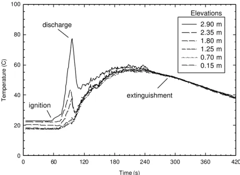
Figure 5a: Room temperatures measured at Thermocouple Tree #1 in Test 1-1 with pool fires, when the single-fluid/high pressure water mist system was employed and the door was closed
ignition discharge extinguishment Elevations Time (s) 0 60 120 180 240 300 360 420 Temperature (C) 0 20 40 60 80 100 2.90 m 2.35 m 1.80 m 1.25 m 0.70 m 0.15 m
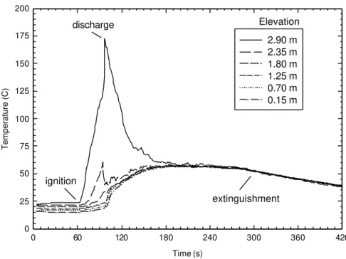
Figure 5b: Room temperatures measured at Thermocouple Tree #2 in Test 1-1 with poo fires, when the single-fluid/high pressure water mist system was employed and the door was closed
ignition discharge
extinguishment
Time (s) 0 60 120 180 240 300 360 420 CO 2 Concentration (%) 0.0 0.5 1.0 1.5 2.0 2.5 3.0 3.5 4.0 2.8 m 1.5 m
Figure 6: CO2 concentrations in the compartment in Test 1-1 with pool fires, when the single-fluid/high pressure water mist system was employed and the door was closed
ignition discharge
extinguishment elevation of sampling port
Time (s) 0 60 120 180 240 300 360 420 Temperature (C) 0 25 50 75 100 125 150 175 200 2.90 m 2.35 m 1.80 m 1.25 m 0.70 m 0.15 m
Figure 5c: Room temperatures measured at Thermocouple Tree #3 in Test 1-1 with pool fires, when the single-fluid/high pressure water mist system was employed and the door was closed
ignition
discharge
extinguishment Elevation
Time (s) 30 60 90 120 150 180 210 240 270 300 330 360 390 420 Temperature (C) 0 20 40 60 80 100 120 140 160 180 200 2.90 m 2.35 m 1.80 m 1.25 m 0.70 m 0.15 m
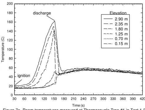
Figure 7a Room temperatures measured at Thermocouple Tree #1 in Test 1-2 with wood crib fires, when the single-fluid/high pressure water mist system was employed and the door was closed
ignition discharge Elevation Time (s) 30 60 90 120 150 180 210 240 270 300 330 360 390 420 Temperature (C) 0 50 100 150 200 250 300 2.90 m 2.35 m 1.80 m 1.25 m 0.70 m 0.15 m
Figure 7b Room temperatures measured at Thermocouple Tree #2 in Test 1-2 with wood crib fires, when the single-fluid/high pressure water mist system was employed and the door was closed.
ignition
discharge
Time (s) 30 60 90 120 150 180 210 240 270 300 330 360 390 420 Temperature (C) 0 50 100 150 200 250 300 350 400 2.90 m 2.35 m 1.80 m 1.25 m 0.70 m 0.15 m
Figure 7c Room temperatures measured at Thermocouple Tree #3 in Test 1-2 with wood crib fires, when the single-fluid/high pressure water mist system was emloyed and the door was closed
ignition discharge Elevation Time (s) 30 60 90 120 150 180 210 240 270 300 330 360 390 420 CO 2 Concentration (%) 0.0 0.5 1.0 1.5 2.0 2.5 3.0 3.5 4.0 2.8 m 1.5 m
Figure 8: CO2 concentrations in the compartment in Test 1-2 with wood crib fire, when the single-fluid/high pressure water mist system was employed and the door was closed
ignition
discharge Elevation of sampling port
Time (s) 0 30 60 90 120 150 180 210 240 Pressure (Pa) -50.0 -40.0 -30.0 -20.0 -10.0 0.0 10.0 20.0 30.0 40.0 50.0
Top pressure tap Middle pressure tap Bottom pressure tap
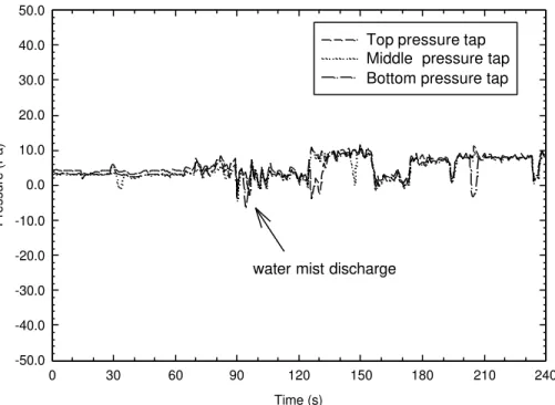
Figure 10 Room pressures in Test 2-1 with pool fires and door open using single-fluid/high pressure water mist system
water mist discharge
Time (s)
0 30 60 90 120 150 180 210 240
Room Pressure (Pa)
-200 -150 -100 -50 0 50
Top pressure tap Middle pressure tap Bottom pressure tap
Figure 11 Room pressures in Test 2-2 with wood crib fires and door open using single-fluid/high pressure water mist system
Time (s) 0 60 120 180 240 300 360 420 Temperature (C) 0 20 40 60 80 100 2.90 m 2.35 m 1.80 m 1.25 m 0.70 m 0.15 m
Figure 12a Room temperatures measured at Thermocouple Tree #1 in Test 2-1 with pool fires, when the single-fluid/high pressure mist system was employed and the door was open.
discharge ignition Elevations Time (s) 0 60 120 180 240 300 360 420 Temperature (C) 0 20 40 60 80 100 2.90 m 2.35 m 1.80 m 1.25 m 0.70 m 0.15 m
Figure 12b Room temperatures measured at Thermocouple Tree #2 in Test 2-1 with pool fires, when the single-fluid/high pressure mist system was employed and the door was open.
discharge
ignition
Time (s) 0 60 120 180 240 300 360 420 Temperature (C) 0 25 50 75 100 125 150 175 200 2.90 m 2.35 m 1.80 m 1.25 m 0.70 m 0.15 m
Figure 12c Room temperatures measured at Thermocouple Tree #3 in Test 2-1 with pool fires, when the single-fluid/high pressure mist system was employed and the door was open.
discharge ignition Elevations Temperature (C) 30 35 40 45 50 55 60 65 70 Room Elevation (m) 0.0 0.5 1.0 1.5 2.0 2.5 3.0
pool fire, door closed pool fire, door open wood crib fire, door closed wood crib fire, door open
Figure 13: Room temperature profiles along the elevations measured at Thermocouple Tree #2 with the door closed/opened at 90 s after discharge with single-fluid/high pressure water mist system
Time (s) 0 30 60 90 120 150 180 210 240 270 300 O2 Concentration (%) 15.0 16.0 17.0 18.0 19.0 20.0 21.0 22.0 door closed door open
Figure 15 O2 concentrations in the compartment with the door closed and open in the spray fire tests, when the single-fluid/high pressure water mist system was employed
ignition discharge Time (s) 0 30 60 90 120 150 180 210 240 270 300 CO 2 Concentration (%) 0.0 0.5 1.0 1.5 2.0 2.5 3.0 3.5 door closed door open
Figure 14: CO2 concentrations in the compartment with the door closed and open in the spray fire test, when the single-fluid/high pressure water mist system was employed.
ignition discharge
Time (s) 0 30 60 90 120 150 180 210 240 270 300 CO 2 Concentration (%) 0.0 0.5 1.0 1.5 2.0 2.5 door closed door open
Figure 17: CO2 concentrations in the compartment with the door closed and open for the pool fire tests, when the twin-fluid/low pressure water mist system was employed.
ignition discharge extinguishment Temperature (C) 30 35 40 45 50 55 60 65 70 Room Elevation (m) 0.0 0.5 1.0 1.5 2.0 2.5 3.0 #1 #2 #3
Figure 16: Room temperature profiles along the elevations measured at thermocouple trees when the door was open for the pool fire tests with twin-fluid/low pressure mist system at 90 s after mist discharge
Temperature (C) 30 40 50 60 70 80 90 100 Room Elevation (m) 0.0 0.5 1.0 1.5 2.0 2.5 3.0 #1 #2 #3
Figure 18: Room temperature profiles along the elevations measured by thermocouple trees under forced ventilation for the spray fire test with twin-fluid/low pressure water mist system at 50 s of discharge
Thermocouple Tree Time (s) 0 30 60 90 120 150 180 210 240 270 300 O2 Concentration (%) 16.0 17.0 18.0 19.0 20.0 21.0 22.0 no ventilation forced ventilation
Figure 19: O2 concentrations in the compartment in the spray fire tests with no ventilation and with forced ventilation, when a twin-fluid/low pressure water mist system was employed in the machinery space
ignition
discharge
Time (s) 0 30 60 90 120 150 180 210 240 270 300 CO 2 Concentration (%) 0.0 0.5 1.0 1.5 2.0 2.5 3.0 3.5 2.8 m (no ventilation) 1.5 m (no ventilation) 2.8 m (forced ventilation) 1.5 m (forced ventilation)
Figure 20: CO2 concentrations in the compartment during the spray fire tests with no ventilation and with forced ventilation, when the twin-fluid/ low pressure water mist system was employed
Sampling Port
ignition