Publisher’s version / Version de l'éditeur:
MATEC Web of Conferences, 165, 2018-05-25
READ THESE TERMS AND CONDITIONS CAREFULLY BEFORE USING THIS WEBSITE. https://nrc-publications.canada.ca/eng/copyright
Vous avez des questions? Nous pouvons vous aider. Pour communiquer directement avec un auteur, consultez la première page de la revue dans laquelle son article a été publié afin de trouver ses coordonnées. Si vous n’arrivez pas à les repérer, communiquez avec nous à [email protected].
Questions? Contact the NRC Publications Archive team at
[email protected]. If you wish to email the authors directly, please see the first page of the publication for their contact information.
Archives des publications du CNRC
This publication could be one of several versions: author’s original, accepted manuscript or the publisher’s version. / La version de cette publication peut être l’une des suivantes : la version prépublication de l’auteur, la version acceptée du manuscrit ou la version de l’éditeur.
For the publisher’s version, please access the DOI link below./ Pour consulter la version de l’éditeur, utilisez le lien DOI ci-dessous.
https://doi.org/10.1051/matecconf/201816518005
Access and use of this website and the material on it are subject to the Terms and Conditions set forth at
Experimental life improvement quantification of shot peening and
fastener modifications
Renaud, Guillaume; Martin, Pascal; Liao, Min
https://publications-cnrc.canada.ca/fra/droits
L’accès à ce site Web et l’utilisation de son contenu sont assujettis aux conditions présentées dans le site
LISEZ CES CONDITIONS ATTENTIVEMENT AVANT D’UTILISER CE SITE WEB.
NRC Publications Record / Notice d'Archives des publications de CNRC:
https://nrc-publications.canada.ca/eng/view/object/?id=a2aa70ab-0d06-457c-984e-b915c674f4e2 https://publications-cnrc.canada.ca/fra/voir/objet/?id=a2aa70ab-0d06-457c-984e-b915c674f4e2*
Experimental Life Improvement Quantification of Shot Peening
and Fastener Modifications
Guillaume Renaud1,*, Pascal Martin2, and Min Liao1
1
National Research Council Canada, 1200 Montreal Road, Ottawa (Ontario), K1A 0R6, Canada 2
L-3 MAS, 10000 Helen Bristol, Mirabel (Québec), J7N 1H3, Canada
Abstract. Two coupon test programs were recently carried out at the National Research Council of Canada to certify shot peening and fastener modifications that aim at extending the lives of military aircraft components that are short of their revised usage goals. The life improvement associated with each modification was experimentally quantified by comparing the lives resulting from variants of each modification with that of pre-modification baseline configurations. This approach allowed determining the effects of several parameters, such as the applied stress level, geometric configuration, and modification specifications, on the life extension.
1 Introduction
Several military aircraft platforms currently undergo life extension retrofit programs to remove fatigue damage accumulation and to delay crack nucleation in aging airframes. These programs are tailored to each aircraft platform to ensure that both airworthiness and logistic risks are maintained at an acceptable level.
The benefit on life resulting from these modifications must typically be determined from tests that are either conservative, or representative of the most critical airframe locations to be reworked. This paper presents two coupon test programs that were recently carried out at the National Research Council of Canada (NRC) to certify modifications aimed at extending the lives of aircraft components short of their revised usage goals. Specifically, the life improvement resulting from robotic shot peening and from fastener replacements was experimentally quantified by comparing the life associated with variants of each modification with that of baseline configurations. This approach allowed evaluating the effect of modification parameters on the life extension, and determining the life benefits that can be included in life predictions for fleet management.
2 Test Programs
The efficiency of the tested life enhancement modification was quantified by comparing the “crack initiation” (CI) lives of coupons with and without the modification. The ratio between these two lives is herein defined as the “life improvement factor” (LIF). The CI life was defined as the time necessary for a fatigue crack to nucleate and grow to 0.01 inch in depth.
2.1 Robotic Shot Peening
First, a robotic shot peening modification was evaluated for the service life extension of major military airframe components. The advantage of using a robotic system for shot peening is to improve quality, repeatability and accessibility on the airframe where a technician has no or very limited access. This cold-working process produces a layer of beneficial compressive residual stress over the treated surface. Up to recently, these shot peening retrofits were carried out prior to 70% of the blueprint fatigue life of the considered aircraft, and assuming a LIF of 1.5.
Recently, new lifing requirements from the fleet operator made necessary to demonstrate a LIF of up to 3.0 in critical areas, along with a retrofit induction as late as 80% of the blueprint life. New tests were required because the available data was insufficient to certify that such LIF was achievable via shot peening for all the considered locations. These locations differed in terms of stress level, required incorporation time, geometry, and material grain orientation. Moreover, a thin layer of material had to be removed prior to shot peening to remove fatigue damage accumulated prior to the rework induction time. The parameters considered in the test plan are summarized in Table 1.
Default values were assumed for each of the physical characteristics to define “main certification tests” that comprised 30 baseline coupons and 30 peened coupons. In addition, “Conditional Tests” were defined in case the shot peening modification could not be certified for all critical locations. These tests, also comprising 30 baseline coupons and 30 peened coupons per series, aimed at identifying parameter values, other than the default, that would allow certification (e.g. earlier retrofit induction).
Table 1. Parameters considered in shot peening tests. Characteristics Test values considered Material Aluminum plate, 6 in thick Stress level (ksi) 5 levels between 50 and 75
Flaw type Surface in middle of radius and edge corner cracks Fillet radius (in) 0.16, 0.25, and 0.38
Stress state Pure uniaxial and some level of bending/shear
Grain direction LT, TL and ST
Marker bands Added or not added in spectrum Spectrum Historical and current spectra;
Fleet 50th% to 90th% severity
Spectrum truncation None or 30%
Manufacturing process Early 1990’s and today Incorporation time 48% to 80% of fatigue life
Blend depth (in) 0.003-0.006 deep to 0.013-0.016 deep
“Sensitivity tests” were also defined to quantify the sensitivity of the shot peening repair effectiveness with respect to selected parameters, particularly when the effectiveness is close to the target value. These tests included between 7 and 15 coupons per series. Finally, “optional tests” were defined to cover other geometries and loading scenarios, if deemed necessary from the results obtained from the other tests.
In total, the number of coupons included in the test matrix ranged between 200 and 579 coupons, depending on how many conditional, sensitivity, and optional tests became required from the main certification tests. The two main coupon geometries considered in the test program are presented in Figure 1.
Fig. 1. Main geometries of shot peening test coupons.
2.2 Fastener Life Improvement Techniques
2.2.1 Blind Interference Fit Fasteners
Second, the fatigue performance resulting from the use of blind interference fit ground shank fasteners (I/F GS) were compared with that of legacy clearance fit blind fasteners with ring pad coining (RPC), that needed to be replaced, and with interference fit Hi-Lok fasteners (I/F HL) that can be used for locations that are accessible from both sides. These comparisons were required to assess retrofit modifications for which several fasteners had to be replaced and/or fastener holes had to be reworked, either for life improvement or for access purposes. However, the LIF of the I/F GS fasteners to be installed was limited by the fleet operator to 2.0. This suggested that the analytical CI life benefit that could be
claimed from the use of these fasteners was lower than that of the RPC or I/F HL, which had an approved LIF of 3.0.
In cases where the local peak stress at the hole is more than 150% of the yield strength (1.5×Fty), the three types of fasteners were attributed a LIF of 1.0. However, this sudden shift from a LIF of 3.0 (or 2.0) to 1.0 when crossing the stress limit limitation was seen as arbitrary and not representative of the actual performance of these fastener systems. Further, assuming the same LIF before and after the modification appeared potentially un-conservative if the I/F GS fastener holes truly have a shorter life than that of the I/F HL or the RPC fasteners. For these reasons, a coupon test program was developed to evaluate the relative difference in LIF between the three fastener systems. The characteristics considered in this program are summarized in Table 2.
Table 2. Parameters considered in fastener tests. Characteristics Test values considered
Material Aluminum plate, 6 in thick Stress level 1.5×Fty and 2.0×Fty
Hole diameter (in) 0.25
Stress state Through and bearing loads: no- and high- load transfer
Grain direction LT
Marker bands Added in spectrum
Spectrum Current spectrum
Spectrum truncation 30%
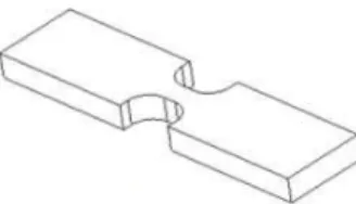
Twelve mandatory and two conditional series of seven coupons were defined to cover baseline cases (open holes) and fastener configurations with and without load transfer. Moreover, each coupon allowed life determination from two identical holes. The geometry of the fastener tests coupons is illustrated in Figure 2.
Fig. 2. Geometry of fastener test coupons (with doublers). The three types of fasteners are presented in Figure 3 (the two blind fastener types look identical; only the coining and engineering fit differ).
a) RPC and I/F GS b) I/F HL Fillet (hot spot)
Note: coupons were tested with or without doublers
Fig. 3. Fastener types (with doublers).
2.2.2 Bushing Repair Evaluation
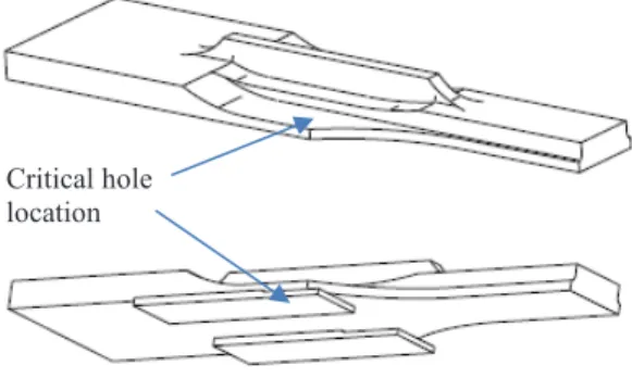
One fastener location stood out amongst those that needed to be reworked as being the most critical from the in-service and full-scale test data reported to date. The complexity of the repair associated with that hole made the current analysis approach unreliable. The repair involves a significant oversizing of the hole, which reduces the benefit from RPC, and bushing installation, which shifts the edge of the hole significantly closer to the edge of the part (lower edge margin). For these reasons, a specific coupon test was developed to certify this repair configuration. In order to match the complex stress field, a 3D coupon was designed, as shown in Figure 4.
Fig. 4. 3D fastener test coupons.
The objective of these tests was to compare the performance of I/F bushing to replace I/F HL fasteners with and without RPC for the repair proposed at that location. First, the CI life for this case was to be determined for the two fastener systems. Then, coupons that would have been previously pre-cycled to a CI state, to simulate a late incorporation time, would be repaired by oversizing the hole and installing a bushing.
Testing of four series of seven coupons was still being performed at the time of writing this paper. As such, no results are reported herein.
2.2.3 Damage Removal Evaluation
Optional tests, not covered in this paper, were also defined to quantify the effect of fatigue damage removal for a nominal to next size fastener typical of the considered modification locations. The objective was to compare experimental fatigue damage removal life results with the current analysis approach. This approach removes fatigue damage by considering the increase in fatigue life from an increase in diameter using Miner’s rule, no matter how much material is removed by a fastener rework. This assumption is potentially overly conservative, especially when enough material is removed such that fatigue life is virtually reset. Four conditional series of seven coupons were defined to cover that requirement.
In total, the number of coupons included in the test matrix for the fastener life improvement techniques ranged between 112 and 154 coupons, depending on how many conditional tests became required from the test results.
2.3 CI Life Improvement Factor Calculation
Fatigue life prediction for the airframe modifications considered in this work must consider uncertainty due to the variability observed in the tests. This variability is related to factors that include material properties, surface condition, rework process control, and geometry. The measure of this variability is given by the standard deviation σ of the log-lives observed in the various test series, which is used to calculate a scatter factor sf for a given probability of failure. This scatter factor is derived using the following equation [1]
sf
Z n n=
+10
1 s (1)where Z is the normal variate for a given cumulative probability of failure, σ is the standard deviation of the observed log-CI lives, and n is the number of test results available. This equation is valid only if the standard deviation is known. In this work it is assumed to be calculated from the test series samples. The equation also assumes that the population from which the test samples are taken is log-normally distributed.
A cumulative probability of failure (CPOF), where failure in this context is “crack initiation” (0.01 inch), of 0.001 (therefore Z = 3.09) was assumed in the current work to derive the scatter factor.
The “safe life” calculated for a test series corresponds to the median life, calculated from a lognormal distribution fit of the test data, divided by the scatter factor. A “factorized” LIF can then be calculated as the ratio between the safe life of a life-enhanced configuration and that of the corresponding baseline (pre-mod) configuration. This approach is illustrated in Figure 5 for a typical shot peening LIF calculation. Critical hole
Fig. 5. Typical CI LIF calculation for shot peening coupons.
An unfactored LIF can also be calculated as the ratio of median coupon CI lives. For the fastener test coupons, life improvement factors were also calculated on crack growth from initiation to coupon failure. This was done to partly isolate the scatter arising from the fastener itself, which would mostly affect short cracks, from the other sources of scatter.
3 Test Requirements and Specifications
3.1 Coupon EtchingTo represent the actual surface condition present on the aircraft, etching was performed on the coupons that assumed that the ion-vapor deposition (IVD) coating applied by the original equipment manufacturer was not removed. The IVD coating itself does not have any impact on the fatigue life but the pre-IVD etching is known to have an effect on crack nucleation.
The objective was to obtain pit depths in the range between 0.006 and 0.010 mm. The etching procedure was certified by measuring pits at various locations along the coupon critical locations. An example of such measurements is presented in Figure 6.
Fig. 6. Typical etch pits.
The shot peening test coupons were etched by complete immersion. This approach was later found to increase the risk of crack nucleation away from the critical fillet (hot spot) where cracks were expected to develop. In order to reduce that risk for the fastener test coupons, only a limited area around the fastener holes was exposed to the etching solution. An example of local
etching is shown in Figure 7. This approach, combined with shot peening of the non-critical coupon surfaces, for instance the radii creating the transition between the coupon grip and gauge test sections, was successful in controlling crack nucleation within the hole area.
Fig. 7. Local etching around pilot holes (3D fastener coupons).
3.2 Initial Setup
The fatigue tests were performed at NRC on MTS test frames equipped with Arbitrary End-Level Compensation, calibrated as per ASTM E4-13 and following the ISO 9001:2008 Standard. Load frame alignment was performed using 12-gauge alignment transducers as per ASTM E1012 Class 5 criteria.
Load spectra were applied using a constant load rate approach, capped at a maximum equivalent frequency of 10 Hz for individual cycles. The selected load rate aimed at minimizing testing time while meeting absolute and relative accuracy of loading, demonstrated for a combination of load frames and coupon geometry, by sequential and statistical analysis of the error for each end point of the first passes of the spectrum. On average, the fatigue loads were applied at an equivalent frequency of approximately 8.25 Hz.
3.3 Periodic Inspections
The life improvement factors were based on the crack initiation life, defined as the time required for a 0.01 inch deep crack to be formed. Whenever possible, crack depth was to be estimated in-situ from periodic non-destructive inspections (NDI).
Initially, inspection of the shot peening coupons started at 80% of the predicted CI life, and then at every subsequent 5% until CI indications could be observed. These inspections were performed using a combination of surface inspection using eddy current testing (ECT) and enhanced liquid penetrant inspection (ELPI) [2]. Quantitative fractography was performed on several coupons of the same geometry and spectrum to calibrate crack depth measurement with these NDI techniques. Examples of such calibrations are presented in Figure 8.
a) Crack depth vs. ECT divisions for baseline coupons
b) Crack depth vs. length (ELPI) for shot-peened coupons
Fig. 8. Calibration of non-destructive inspection techniques
In general, it was observed that ECI provided better crack depth estimations for baseline (non-peened) coupons, whereas ELPI was more efficient on shot-peened surfaces. This method for rapid crack detection has been shown to be able to detect cracks less than 0.004 inch in length in shot-peened surfaces, and able to reliably measure 0.01 inch cracks [2]. For un-etched baseline coupons however, where machining marks ran parallel to the cracks, small crack were difficult to measure with this technique. Examples of cracks observed using ELPI are presented in Figure 9.
a) Baseline surface b) Shot-peened surface
Fig. 9. Examples of enhanced liquid penetrant inspection.
The two NDI techniques were fast but could provide only estimates of the crack depth. Moreover, crack detection was found to be difficult in some cases, resulting in potentially “missed” initiation. It was found that one to three additional measurements after CI could increase the confidence in the approximate initiation life. However, in some cases it was necessary to open the crack and determine the CI life from quantitative fractography. This technique is much slower but able to measure crack depth more accurately. Moreover, being able to measure the CI life after complete coupon failure, it makes periodic inspection unnecessary, which means that the test frames can be used more efficiently, without interruption.
3.4 Quantitative Fractography
Marker bands were added to the test spectra to allow quantitative fractography analysis of the coupons. The marker band type selected for the shot peening coupons was a series of two cycles with a peak and valley of 85% and -10% of the maximum spectrum load, respectively, followed by 200 cycles with a peak of 75% and valley of 50%. This pattern, which was repeated twice at the end
of the spectrum block, was clearly visible for the historical spectrum but difficult to see for the current target spectrum, which self-marked similar bands.
A “bar-coding” type of marker band was used for the fastener tests [3]. In this case, eight different bar code patterns, combining cycles that ranged from 85% to 60% and cycles that ranged from 85% to 10%, were inserted over two passes of the spectrum. The use of different patterns, repeated only every two blocks, significantly increased the confidence in the time-stamping of the marker bands. The different bar code patterns are illustrated in Figure 10.
Fig. 10. Bar code marker band scheme (taken from [3]).
Because most of the fastener test coupons were assemblies with the test section being the fastener holes, it was not possible to detect CI using NDI. Indeed, for these coupons the nucleation points were either hidden under fastener collars or heads, or under doublers. Therefore, CI for the fastener test program was determined solely via quantitative fractography performed after complete coupon failure.
4 Results
4.1 Robotic Shot Peening
In total, 166 shot peening coupons were tested. The high life extension efficiency of the modification made possible to waive several test series and test less than the planned minimum of 200 coupons.
4.1.1 Correlation with Previous Test Program First, a group of 42 coupons were tested to verify if a reasonably simple coupon shape (Figure 1, right) would provide results similar to a previous test program which was using a more complex 3D shape (Figure 11). These tests were carried out at three local stress levels (72.5 ksi, 62.9 ksi, 55.2 ksi) to quantify the sensitivity of the LIF with respect to the applied load.
Overall, the scatter observed on the new coupon geometry was higher than that on the previous 3D shape. This result was explained by the fact that the hot spot on the previous shape was a point, whereas it is a line on the new coupons. The calculated factored LIF was observed to increase with decreasing local stress, being at 3.89 for the highest load, and 8.17, and 12.18 for the moderate and lowest load, respectively. Furthermore, the scatter in baseline lives was also found to significantly increase when reducing the applied loads. The peened surface, on the other hand, made the life scatter much more consistent
Table 3. Correlation with previous test results. Local Stress (ksi) Scatter Factor (baseline / peened) Unfactored LIF Factored LIF 72.5 2.26 / 2.66 4.57 3.89 62.9 3.89 / 1.89 3.98 8.17 55.2 5.63 / 2.18 >4.71* >12.18*
*Three of the peened coupons failed at the grips
These results show that under a local stress of 72.5 ksi the simple geometry was slightly conservative with respect to the previous 3D geometry, for which a factored LIF value of 4.74 had been determined. They confirmed that this stress level was applicable for the main certification tests.
4.1.2 Main Certification Tests
A group of 30 baseline and 30 peened coupons were tested for the main certification tests. Since some of the baseline coupons were rejected because they were manufactured out of tolerance, a second test point was extracted from the coupons, when available. In total, 49 test points were obtained for the baseline coupons, with a scatter factor of 2.08 in life. The manufacturing tolerance was tighten for the subsequent test groups.
The certification methodology was to pre-cycle the coupons to simulate a late rework introduction, at 80% of the blueprint aircraft life. The exact pre-cycling time was adjusted by taking into account the difference between the life scatter observed in the tests and fleet. The repair consisted in a 0.003 to 0.006 inch deep blend followed by robotic shot peening.
It was quickly realized that the rework performed so well at the hot spot that the coupons, not designed to sustain such high lives, started to crack in the grip area, due to fretting, and at the sharp edges of the pocket, which had been distorted at the microscopic scale by peening. These problems were partly resolved by developing a new protective layer to be installed between the grips and the coupons, which delayed and eventually eliminated fretting failure under the grips, and by adding a chamfer on the coupon pocket edge.
Overall, only five of the 30 coupons cracked in the hot spot, with an average factored LIF of 8.4. The other 25 coupons did not reach CI in the hot spot; ten failed from the pocket edge, and 15 failed in the grip area. Out of the five coupons that cracked at the hot spot, two showed clear NDI crack indications before rework and
then were cycled up to a LIF of approximately 5.0 and 6.0. The other three cracks had much higher LIF values, between 10.0 and 14.8. Conservatively mixing the two CI lives for which cracks were present before the rework, the three other CI lives determined at the hot spot, and the lives of the 25 coupons that failed before CI was reached at the hot spot (conservative), an average life ratio of 8.4 was obtained, along with a standard deviation twice as large as that of the baselines series. Using these numbers, a conservative factored LIF of 5.0 was determined.
Therefore, although the main certification tests did not allow to perform an accurate statistical evaluation on the variability of extended life due to shot peening, they clearly showed that the considered rework performed as late as 80% of the blueprint life provides a LIF significantly above the required value of 3.0. With these results, several conditional, sensitivity, and optional tests were waived (deeper blend, earlier peen and lower stress, bending stress field, effect of marker bands, effect of spectrum truncation).
4.1.3 Sensitivity Tests
Several sensitivity tests were performed to quantify the effects of various parameters on the calculated LIF. First, the shot peening LIF for cracks on edges, as opposed to pocket radii, was evaluated using the coupons illustrated in Figure 12. All coupons in the baseline series were cycled to rupture, then analysed by quantitative fractography. The lives of the peened coupons, however, were so long that cycling was stopped before CI was detected. A minimum LIF of 16.0 was demonstrated for the edge crack sensitivity tests.
Fig. 12. Shot peened coupon for edge crack sensitivity test.
Another test series was performed to evaluate if the shot peening rework would be less efficient when the loading was in the short transverse (ST) grain direction. A minimum LIF of 9.0 was demonstrated.
Tests were performed to evaluate the effects of applying a 50thpercentile usage spectrum severity vs. the 90thseverity used for all the other tests. A minimum LIF of 8.9 was demonstrated.
Finally, tests were performed to simulate the scenario where 0.015 inch deep cracks were introduced before the rework. First, the coupons were pre-cycled until NDI suggested that the target crack depth was achieved. Then, the hot spot was modified by a 0.003 to 0.006 inch blend flowed by shot peening over the leftover cracks. The objective of these tests was to estimate the scatter and growth rate of such cracks when not completely removed before peening. As shown in Figure 13, kinks were observed in the crack growth curve between 0.010
inch and 0.012 inch, indicating the depth of the beneficial compressive stress layer. Once passed the layer, the crack growth rate was fairly uniform among peened coupons, and similar to that of the baseline coupons. Therefore, the balancing residual tensile stress did not significantly accelerate crack growth.
Fig. 13. Crack growth for retrofit on a 0.015 inch crack.
4.2 Fastener Life Improvement Techniques
At the time of writing this paper, testing of the 84 mandatory coupons forming the main fastener test group was completed, and testing of the more complex 3D coupons (bushing repair) was underway. For the fastener tests, all LIF values were calculated using CI lives determined from fractography. A typical example of the crack growth curves obtained is presented in Figure 14.
Fig. 14. Typical quantitative fractography on fastener coupons.
Factored and unfactored LIF values resulting from the three fastener types were calculated using baseline open hole coupons subject to the same peak local stress. A summary of the factored LIF values for crack initiation CI is presented in Table 4.
As assumed by the fleet operator, the CI LIF associated with the blind I/F GS fasteners is less than those obtained from the other two fastener systems. The only exception observed was for the of high stress case with load transfer, for which the I/F GS fasteners performed exceptionally well in the tests.
However, the assumption that the LIF is reduced beyond a stress level of 1.5×Fty up to 2.0×Fty cannot be confirmed from the test results. If fact, the test results suggest that the LIF increases when the local stress increases. This result is partly due the fact that the scatter factor is higher for low stress, which reduces the factored LIF.
Table 4. Fastener LIF comparison. Fastener Type Load Transfer Local Stress (×Fty) Factored CI LIF Scatter Factor RPC Yes 1.5 In process 2.0 5.46 1.79 No 1.5 7.94 1.38 2.0 8.82 1.74 I/F HL
Yes 1.5 Conditional Tests 2.0 No 1.5 5.36 3.95 2.0 8.26 3.19 I/F GS Yes 1.5 3.27 4.42 2.0 12.77 1.80 No 1.5 2.06 4.99 2.0 5.32 2.74
5 Conclusion
The objective of a shot peening coupon test program carried out recently at NRC was to demonstrate if a minimum LIF of 3.0 could be obtained from a robotic shot peening modification to be implemented at specific airframe critical locations. All test series demonstrated a LIF value above 3.0. Even for the main certification tests that simulated a modification as late as 80% of the blueprint life of the aircraft, the resulting LIF was significantly above the requirement. It was therefore recommended that a LIF of 3.0 could “safely” be assumed for the considered shot peening modifications.
The objective of another life extension certification program, still being carried out at NRC, was to determine if a life extension penalty should be considered when blind interference fit ground shank fasteners (I/F GS) were to be used instead of clearance fit blind fasteners with ring pad coining (RPC), or interference fit Hi-Lok (I/F HL) fasteners. Further, the life extension performance of these three fastener types were to be evaluated for highly loaded situations. Results obtained to date suggest that the I/F GS fasteners do not provide as much life extension as the other two fastener types. Furthermore, contrary to current assumption from the fleet operator, the factored LIF is not reduced when the stress goes from 1.5×Fty up to 2.0×Fty. More tests could be performed with the intent to identify the stress limit where the LIF starts to decrease.
This work was funded by the United States Navy Naval Air System Commands (NAVAIR). The etching process and marker band schemes were provided by the Defence Science and Technology (DST) Group of Australia.
1. N.I. Bullen, “A Note on Test Factors”, A.R.C. Technical Report, R and M 3166 (1961)
2. M. Yanishevsky, “An Enhanced Fluorescent Liquid Penetrant Inspection Technique for Measurement of Surface Cracks”, First Pan-American Conference for Nondestructive Testing, Toronto, Canada (1998) 3. M. Burchill, S. Barter, and M. McDonald, “The
Development of Bar-Coded Marker Band Load Sequences to Enhance Fatigue Test Outcomes”, 16th Australian International Aerospace Conference, (2015)