20 years of research on the Alcator C-Mod tokamak
The MIT Faculty has made this article openly available. Please share how this access benefits you. Your story matters.Citation Greenwald, M., A. Bader, S. Baek, M. Bakhtiari, H. Barnard, W. Beck,
W. Bergerson, et al. “20 Years of Research on the Alcator C-Mod Tokamaka).” Phys. Plasmas 21, no. 11 (November 2014): 110501.
As Published http://dx.doi.org/10.1063/1.4901920
Publisher American Institute of Physics (AIP)
Version Author's final manuscript
Citable link http://hdl.handle.net/1721.1/98289
Terms of Use Creative Commons Attribution-Noncommercial-Share Alike
PSFC/JA-14-21
20 Years of Research on the Alcator C-Mod Tokamak
M. Greenwald1, A. Bader2, S. Baek1, M. Bakhtiari2, H. Barnard1, W. Beck1, W. Bergerson3,
I. Bespamyatnov4, P. Bonoli1, D. Brower3, D. Brunner1, W. Burke1, J. Candy5, M. Churchill6, I. Cziegler7,
A. Diallo6, A. Dominguez6, B. Duval8, E. Edlund6, P. Ennever1, D. Ernst1, I. Faust1, C. Fiore1, T. Fredian1,
O. Garcia9, C. Gao1, J. Goetz2, T. Golfinopoulos1, R. Granetz1, O. Grulke10, Z. Hartwig1, S. Horne11,
N. Howard12, A. Hubbard1, J. Hughes1, I. Hutchinson1, J. Irby1, V. Izzo7, C. Kessel6, B. LaBombard1,
C. Lau27, C. Li1, Y. Lin1, B. Lipschultz13, A. Loarte14, E. Marmar1, A. Mazurenko15, G. McCracken16,
R. McDermott17, O. Meneghini5, D. Mikkelsen6, D. Mossessian18, R. Mumgaard1, J. Myra19,
E. Nelson-Melby20, R. Ochoukov17, G. Olynyk21, R. Parker1, S. Pitcher14, Y. Podpaly22, M. Porkolab1,
M. Reinke13, J. Rice1, W. Rowan4, A. Schmidt23, S. Scott6, S. Shiraiwa1, J. Sierchio1, N. Smick24,
J.A. Snipes14, P. Snyder5, B. Sorbom1, J. Stillerman1, C. Sung1, Y. Takase25, V. Tang23, J. Terry1,
D. Terry1, C. Theiler8, A. Tronchin-James26, N. Tsujii25, R. Vieira1, J. Walk1, G. Wallace1, A. White1,
D. Whyte1, J. Wilson6, S. Wolfe1, G. Wright1, J. Wright1, S. Wukitch1, S. Zweben6 1 MIT Plasma Science & Fusion Center, Cambridge, MA 02139
2 Dept. of Physics, U. Wisconsin, Madison, WI, 53706
3 UCLA, Institute of Plasma & Fusion Research, Los Angeles, CA, 90095 4 U. Texas, Fusion Research Center, Austin, TX, 78712
5 General Atomics, P.O. Box 85608, San Diego, CA, 92186 6 Princeton Plasma Physics Laboratory, Princeton, NJ, 08540
7 UCSD, Center for Momentum Transport and Flow Organization, San Diego, CA, 92093 8 Ecole Polytechnique Federale de Lausanne, Centre de Recherches en Physique des Plasmas,
Lausanne 1015, Switzerland
9 Department of Physics and Technology, University of Tromsø, N-9037 Tromsø, Norway 10 MPI for Plasma Physics, EURATOM Association, D-17491 Greifswald, Germany and
Ernst-Moritz-Arndt University, D-17489 Greifswald, Germany
11 Energetiq Technology, 7 Constitution Way, Woburn, MA 01801
12 Oak Ridge Institute for Science and Education (ORISE), Oak Ridge, TN, 37830 13 York University, Heslington, York YO10 5DD, United Kingdom
14 ITER Organization, 13067 St. Paul-lez-Durance
15 Block Engineering, 377 Simarano Dr, Marlborough, MA, 01752
16 UKAEA Culham Centre for Fusion Energy, Abingdon, OX14 3DB, Oxfordshire, U.K. 17 MPI für Plasmaphysik, EURATOM-Association., D-85748 Garching, Germany 18 AllianceBernstein, 1345 Avenue of the Americas, New York, NY 10105 19 Lodestar Research Corporation, 2400 Central Avenue P-5, Boulder, CO 80301 20 Raytheon Co., 1151 E Hermans Rd, Tucson, AZ 85756
21 McKinsey & Co, 110 Charles Street West Toronto, ON M5S 1K9 Canada
22 National Institute of Science & Technology, 100 Bureau Drive, Stop 1070, Gaithersburg,
MD 20899
23 LLNL, 7000 East Ave, Livermore, CA 94550
24 GT Advanced Technologies, 243 Daniel Webster Highway, Merrimack, NH 03054 25 U. Tokyo, Tokyo 113-033, Japan
26 Facebook LLC, 1601 Willow Road, Menlo Park, CA 94205 27 ORNL, P.O. Box 2008, Oak Ridge, TN 37831
August 2014
Plasma Science and Fusion Center Massachusetts Institute of Technology
Cambridge MA 02139 USA
This work was supported by the United States Department of Energy (DOE), mainly under cooperative agreement C-Mod: DE-FC02-99ER54512 but also under DE-FG03-94ER-54241, 78ET-51013, DE-AC02-09CH11466, DE-FG02-95ER54309, DE-AC02-05CH11231, DE-AC52-07NA27344, DE-FG02-97ER54392, DE-SC00-02060. Other Contributors have been funded through NSF DMR-08-19762, the Swiss National Science Foundation and the Alexander-von-Humboldt Foundation among others. Reproduction, translation, publication, use and disposal, in whole or in part, by or for the United States government is permitted.
20 Years of Research on the Alcator C-Mod Tokamak
M. Greenwald1, A. Bader2, S. Baek1, M. Bakhtiari2, H. Barnard1, W. Beck1, W. Bergerson3, I. Bespamyatnov4, P. Bonoli1, D. Brower3, D. Brunner1, W. Burke1, J. Candy5, M. Churchill6, I. Cziegler7, A. Diallo6, A. Dominguez6, B. Duval8, E. Edlund6, P. Ennever1, D. Ernst1, I. Faust1, C. Fiore1, T. Fredian1, O. Garcia9, C. Gao1, J. Goetz,2, T. Golfinopoulos1, R. Granetz1, O. Grulke10, Z. Hartwig1, S. Horne11, N. Howard12, A. Hubbard1, J. Hughes1, I. Hutchinson1, J. Irby1, V. Izzo7, C. Kessel6, B. LaBombard1, C. Lau27, C. Li1, Y. Lin1, B. Lipschultz13, A. Loarte14, E. Marmar1, A. Mazurenko15, G. McCracken16, R. McDermott17, O. Meneghini5, D. Mikkelsen6, D. Mossessian18, R. Mumgaard1, J. Myra19, E. Nelson-Melby20, R. Ochoukov17, G. Olynyk21, R. Parker1, S. Pitcher14, Y. Podpaly22, M. Porkolab1, M. Reinke13, J. Rice1, W. Rowan4, A. Schmidt23, S. Scott6, S. Shiraiwa1, J. Sierchio1, N. Smick24, J.A. Snipes14, P. Snyder5, B. Sorbom1, J. Stillerman1, C. Sung1, Y. Takase25, V. Tang23, J. Terry1, D. Terry1, C. Theiler8, A. Tronchin-James26, N. Tsujii25, R. Viera1, J. Walk1, G. Wallace1, A. White1, D. Whyte1, J. Wilson6, S. Wolfe1, G. Wright1, J. Wright1, S. Wukitch1, S. Zweben6
1 MIT Plasma Science & Fusion Center, Cambridge, MA 02139 2 Dept. of Physics, U. Wisconsin, Madison, WI, 53706
3 UCLA, Institute of Plasma & Fusion Research, Los Angeles, CA, 90095 4 U. Texas, Fusion Research Center, Austin, TX, 78712
5 General Atomics, P.O. Box 85608, San Diego, CA, 92186 6 Princeton Plasma Physics Laboratory, Princeton, NJ, 08540
7 UCSD, Center for Momentum Transport and Flow Organization, San Diego, CA, 92093
8 Ecole Polytechnique Federale de Lausanne, Centre de Recherches en Physique des Plasmas, Lausanne 1015,
Switzerland
9 Department of Physics and Technology, University of Tromsø, N-9037 Tromsø, Norway
10 MPI for Plasma Physics, EURATOM Association, D-17491 Greifswald, Germany and Ernst-Moritz-Arndt
University, D-17489 Greifswald, Germany
11 Energetiq Technology, 7 Constitution Way, Woburn, MA 01801
12 Oak Ridge Institute for Science and Education (ORISE), Oak Ridge, TN, 37830 13 York University, Heslington, York YO10 5DD, United Kingdom
14 ITER Organization, 13067 St. Paul-lez-Durance
15 Block Engineering, 377 Simarano Dr, Marlborough, MA, 01752
16 UKAEA Culham Centre for Fusion Energy, Abingdon, OX14 3DB, Oxfordshire, U.K. 17 MPI für Plasmaphysik, EURATOM-Association., D-85748 Garching, Germany 18 AllianceBernstein, 1345 Avenue of the Americas, New York, NY 10105 19 Lodestar Research Corporation, 2400 Central Avenue P-5, Boulder, CO 80301 20 Raytheon Co., 1151 E Hermans Rd, Tucson, AZ 85756
21 McKinsey & Co, 110 Charles Street West Toronto, ON M5S 1K9 Canada
22 National Institute of Science & Technology, 100 Bureau Drive, Stop 1070, Gaithersburg, MD 20899 23 LLNL, 7000 East Ave, Livermore, CA 94550
24 GT Advanced Technologies, 243 Daniel Webster Highway, Merrimack, NH 03054 25 U. Tokyo, Tokyo 113-033, Japan
26 Facebook LLC, 1601 Willow Road, Menlo Park, CA 94205 27 ORNL, P.O. Box 2008, Oak Ridge, TN 37831
20 Years of Research on the Alcator C-Mod Tokamak
Abstract
The object of this review is to summarize the achievements of research on the Alcator C-Mod tokamak [I. H. Hutchinson et al., Physics of Plasmas 1, 1511 (1994), E. S. Marmar, Fusion Science and Technology 51, 261 (2007)] and to place that research in the context of the quest for practical fusion energy. C-Mod is a compact, high-field tokamak, whose unique design and operating parameters have produced a wealth of new and important results since it began operation in 1993, contributing data that extends tests of critical physical models into new parameter ranges and into new regimes. Using only high-power radio frequencey (RF) waves for heating and current drive with innovative launching structures, C-Mod operates routinely at reactor level power densities and achieves plasma pressures higher than any other toroidal confinement device. C-Mod spearheaded the development of the vertical-target divertor and has always operated with high-Z metal plasma facing components - approaches subsequently adopted for ITER. C-Mod has made ground-breaking discoveries in divertor physics and plasma-material interactions at reactor-like power and particle fluxes and elucidated the critical role of cross-field transport in divertor operation, edge flows and the tokamak density limit. C-Mod developed the I-mode and Enhanced Dα H-mode regimes which have high performance without large ELMs and with pedestal transport self-regulated by short-wavelength electromagnetic waves. C-Mod has carried out pioneering studies of intrinsic rotation and demonstrated that self-generated flow shear can be strong enough in some cases to significantly modify transport. C-Mod made the first quantitative link between pedestal temperature and H-mode performance, showing that the observed self-similar temperature profiles were consistent with critical-gradient-length theories and followed up with quantitative tests of nonlinear gyrokinetic models. RF research highlights include direct experimental observation of ICRF mode-conversion, ICRF flow drive, demonstration of Lower-Hybrid current drive at ITER-like densities and fields and, using a set of powerful new diagnostics, extensive validation of advanced RF codes. Disruption studies on C-Mod provided the first observation of axisymmetric halo currents and non-axisymmetric radiation in mitigated disruptions. A summary of important achievements and discoveries are included in section IX.
I. Introduction - Advantages of High Magnetic-field for Fusion
While it is common and correct to frame pure plasma physics phenomena in terms of dimensionless plasma parameters1,2, practical fusion energy requires prescribed levels of absolute performance. This can be easily understood as a consequence of non-plasma dimensionless parameters, particularly the ratio of plasma temperature to the characteristic energies required for the fusion nuclear reaction (kT/Enuclear) and to the characteristic energies for
atomic ionization, recombination and molecular bonding (kT/Eatomic). The first of these leads
directly to the Lawson criterion for the minimum ion temperature in an energy producing fusion plasma. The second is important for edge plasma and plasma-wall interactions and will be discussed in sections I.A and III. Economic and engineering considerations dictate the optimum level of neutron wall loading in a fusion reactor3 (about 3-4 MW/m2) and consequently to an
optimum absolute plasma pressure and density. At the same time, all of the operating limits for a tokamak increase with the magnetic field; the maximum plasma current, which largely determines confinement and the maximum plasma density are proportional to B 4,5 and the maximum pressure is proportional to B2 6. Thus absolute performance increases with field, as does robustness against disruptions due to the proximity of operational limits. It is worth noting that the requirement for operation near an optimum density can be problematic for very large low-field fusion reactor designs, since this density range may be above the tokamak density limit7. Prospective tokamak reactor designs like ARIES-AT assume operation near or above all of these limits8 raising concern about achieving this level of performance and robustness with respect to disruptions. Research at fusion-relevant absolute parameters is required since the plasma and non-plasma physics couple in complicated ways that are well beyond our current abilities to model.
The economic advantage of high fields can be understood by considering the total fusion power from a tokamak device which is proportional to
(
β
N/ q
)
2R B
3 4 where βN is the plasmapressure normalized to the Troyon limit6 and q is the tokamak “safety” factor, the inverse of the rotational transform. Plasma physics sets the upper limit for βN and the lower limit for q. The
overall cost for a fusion facility is proportional to the mass of the fusion “core” and thus to the magnetic stored energy
∝
R B
3 2. From these arguments, it is clear that the most cost effective fusion devices would operate with the highest fields that can be safely engineered. On several previous occasions when the U.S. was planning to build its own burning plasma devices, CIT, BPX and FIRE 9,10, the price to performance argument led to compact high-field designs. Looking forward and considering the substantial costs and extended construction schedule for ITER, which was designed with “well-known” moderate-field superconducting magnet technology, a development path that features higher field seems attractive.A discussion of the practical limits for the strength of magnetic field in a fusion device is beyond the scope of this paper, but it is worth noting the opportunities presented by recent developments in high temperature superconductors. These materials, YBCO for example, have demonstrated significantly higher critical currents at fields above 20T11. By operating at elevated temperatures where heat capacities are higher, it should be possible to build magnets with field-demountable joints, allowing much more favorable modes for construction and maintenance. A design concept for a high-field pilot plant has been developed, demonstrating the advantages of this approach12. A limiting factor, of course, would be the ability to provide the mechanical support for the magnetic stresses produced by high-field magnets, though the design efforts described above suggest that this should be achievable.
A. Consequences of High-field Operation in C-Mod
Alcator C-Mod is the third in a series of compact high-field tokamaks built and operated on the MIT campus13,14. Supporting the arguments provided above, these machines have demonstrated high performance at moderate size and cost - the previous device, Alcator C, being the first controlled fusion experiment to exceed the Lawson product for density times confinement15. An important early goal of the C-Mod program was to provide a database that is relevant to
field regimes. This goal encompassed support for the design and operation of ITER, whose toroidal field of 5.4 T exceeds every other shaped and diverted tokamak in the world except for C-Mod. Table I provides a summary of basic parameters for the device.
TABLE I. C-Mod physics parameters and symbols used in this manuscript
Parameter Symbol Range Units/Definition
Major radius R 0.67 m
Minor radius a 0.22 m
Plasma elongation κ 1.0-1.9
Plasma triangularity δ 0.0-0.85
Plasma volume V 1 m3
Toroidal magnetic field BT 2.4-8.1 T
Plasma current IP 0.24-2.0 MA
Average plasma density ne 0.2-8.0 1020/m3
Central electron temperature Te < 9 keV
Central ion temperature Ti < 6 keV
Average plasma pressure p <0.18 MPa
Normalized gyro-radius ρ* 0.002-0.006 ρi/a
Normalized pressure βΝ <1.8 βT/IP/aBT
Normalized collisionality ν* 0.06-1.0 νeiqR/ε3/2vi
Operation at high field also allows attainment of uniquely ITER/reactor-relevant physics regimes. Consider for example the boundary plasma, where the plasma interacts with the wall, neutral fuel gas and impurities. The nature of these interactions depends strongly on the plasma temperature normalized to atomic binding energies which are on the order of a few eV. Thus survival of plasma-facing components depends on lowering the plasma temperature at the interface to less than 10 eV. Fixing this value as a requirement for safe operation, the remaining boundary plasma parameters depend on the pressure. Thus C-Mod, operating at reactor-like magnetic fields, operates at reactor-like boundary plasma pressures and thus has the same absolute power and particle loads, plasma density and neutral opacity. As a consequence, a wide range of boundary phenomena can be studied directly on C-Mod, without resort to scaling arguments or excessive dependence on models. Similarly for RF physics, C-Mod runs with the same cyclotron frequency (same field) and plasma frequency (same plasma density) as ITER and by carrying out experiments with the same RF frequencies can operate with identical wave physics. At the same time, by operating in a unique range of field, input power and size, C-Mod made critical contributions to multi-machine databases which breaks parameter covariances when combined with larger low-field devices. For example, the inclusion of C-Mod data led to the ITER98 scalings for energy confinement in H-mode, in which an unconstrained regression
yielded a dimensionally correct fit16. Previous regressions carried out before C-Mod data were available were not dimensionally correct and in fact failed to predict the eventual C-Mod results, pointing out the risks in extrapolating from inadequately conditioned data17. In a similar vein, C-Mod provided critical data for disruption physics, the L-H threshold, boundary plasmas, H-mode pedestals and core particle transport used for defining the ITER operational baseline 7,18. Given this background – the ability to operate in relevant regimes, with a good diagnostic set – it was inevitable that C-Mod would make a series of discoveries and address issues important for fusion energy.
II. C-Mod – Features and Engineering A. Magnets, Structure and Control
C-Mod’s unique physics capabilities flow directly from its high-field magnet technology19. The toroidal field (TF) magnet consists of 20 6-turn copper coils carrying 225 kA at full field. Each coil is rectangular and composed of 4 straight segments with sliding joints at the corners. The joints are not pinned but rather are free to move under full current, transferring most of the magnetic stress from the coil to an external structure. These forces, which can reach up to 110 MN, are supported by a cylinder, 0.15 m thick, 4.9 m in diameter together with top and bottom domes, each 0.66 m thick with all three parts forged from high strength 316LN stainless steel and precision machined. The domes are fastened to the cylinder by 96 pretensioned INCONEL 718 drawbars forming a massive pressure vessel. Weighing about 30 tons each, the domes and cylinder were some of the largest stainless steel forgings ever made. A pair of monolithic wedge plates holds the magnet bundles in place and restrains the overturning forces of the magnet. Internal stresses in each bundle are supported by the high-strength copper and reinforced by stainless steel plates that are inserted, with insulation, between each turn. Figure 1 shows a schematic of the machine and the major components mentioned here. A great deal of R&D went into the felt-metal sliding connections that are the key to this design20. With 120 turns, each made of 4 segments, there are a 480 joints that must slide under full current and full mechanical load with minimal wear, while maintaining very low electrical resistivity. Each joint has 4 felt-metal pads, with a total area of 72 cm2, made of copper wire, sintered onto a copper substrate, silver plated and coated with colloidal graphite. Spring-plates are hydraulically driven in between the TF joint fingers to provide the required contact pressure. The resulting resistance is below 1.5µOhm for each joint. The TF magnet is disassembled for inspection roughly every 5,000 pulses. The TF and poloidal field (PF) magnets are all cooled to LN2 temperatures to
reduce their electrical resistance. Thermal management in C-Mod is challenging, requiring that the vessel and ports be kept at room temperature while the magnets are kept cold. Clearances are small due to the compact size of the device. Table II provides a summary of C-Mod engineering parameters.
Another critical innovation was made in the buss connections which bring power to several of the poloidal field (PF) magnets. To accommodate the high current densities required and dimensional changes during heating and cooling, compliant buss connections were fabricated with electro-forming technology, an additive manufacturing process that produces stress-free high strength joints – compared to standard welding or brazing techniques which anneal and
weaken underlying material. The poloidal field magnets themselves are of more conventional design. The Ohmic Heating (OH) coil is made of 3 segments and is wound directly on the TF central column. The C-Mod OH coils require 30 kA currents to be supplied across magnetic fields above 17 T. A coaxial design allows the inner and outer conductor forces to react against each other to produce a very strong structure. The connection to the OH stack includes electric-discharge-machined 25 µm wide slots acting as springs along with a Belleville stack to provide compliance to the feltmetal contacts. This design has performed extremely well in handling both the extreme electromagnetic forces and the thermal stresses over many thousands of C-Mod shot cycles. The remaining PF coils are supported by the vacuum vessel, which is a structural element of the machine with thickness varying from 1.5 to 5 cm. Power for the magnets is provided by an alternator and flywheel storing 2 GJ of kinetic energy and driven by a 4,000 horse-power motor. 250 MVA can be extracted from the alternator during a pulse and is supplemented by 24 MVA from the local electrical utility. Twelve independent power convertors supply current to the machine’s magnets. For the first 14 years of its operation, C-Mod plasma control was via a hybrid digital-analog controller provided through a collaboration with the CRRP-EPFL21. More recently an all digital real-time control system was implemented using a conventional linux server and I/O cards on a CompactPCI bus22. Instrumentation and control is handled by ≈30 industrial programmable logic controllers with mimic screens in the control room23. Pulse coordination, data acquisition, data management and automated analysis are provided through the MDSplus data system24. The client-server capabilities of MDSplus allowed C-Mod to demonstrate the first remote operation of a fusion experiment25.
B. Internal Hardware
From the start, plasma facing components (PFCs) in C-Mod were built to withstand the very high heat fluxes and mechanical loads that were anticipated. The design featured a vertical target lower divertor and refractory metals on all surfaces that could come into contact with the plasma. The machine can also run with an upper x-point on a flat target divertor behind which is installed a toroidal cryopump with an effective pumping speed for D2 of 10,000 l/s. The choice of high-Z
metals was controversial at the time as earlier experience with tungsten limiters on PLT26 convinced a generation of fusion scientists that these materials were not practical. However, the C-Mod team believed that graphite and carbon composites would not be acceptable materials in a reactor and that the fusion program needed data that could demonstrate the advantages and overcome the challenges of refractory metals. The 20 years of experience gained on C-Mod in the relevant operational space has been a critical element in decisions made for the ITER first wall design. The C-Mod wall was originally faced with 7,000 tiles made of the molybdenum alloy TZM (99.5% Mo, 0.5% Ti, 0.08% Zr) installed on backing plates made of INCONEL or stainless steel depending on the strength required27. The large number of relatively small tiles was required to limit the forces due to eddy currents induced in the vessel during disruptions. The metallurgy of the raw material was important for the ability of these tiles to survive the thermal and mechanical shocks that they were subjected to. A belt of tungsten tiles was installed in the highest heat flux areas for several run periods for evaluation of a possible ITER design and to allow measurements of material erosion and migration. Figure 2 is a recent image of the internal hardware showing the divertor, inner wall tiles, RF launchers and internal diagnostics. Because of the compact size of the device and port space further limited by the heavy build of
the magnets, a large amount of hardware is mounted on the tokamak wall. Over time, the C-Mod team has learned how to design, fabricate and install hardware that can be subject to significant heat loads and disruption forces.
For machine conditioning, the thick, low-resistance vacuum vessel precluded any possibility of “Taylor” discharge cleaning which had been the standard procedure on previous Alcator devices. Instead, C-Mod surfaces are prepared for operation via Electron Cyclotron Discharge Cleaning (ECDC) using a 2.5kW klystron operating at 2.54 GHz28. The toroidal field is operated near 0.09 T and slowly swept so that the discharge intercepts all of the internal structures. After a period of baking, discharge cleaning and initial operations, the plasma facing surfaces are typically covered with a thin film of boron by running discharge cleaning with deuterated diborane (10 % B2D6 in 90% He background). Approximately 100nm is deposited weekly when operating29. C. Impact of the Machine Design for the C-Mod Physics Program
While the nature of the C-Mod device allows operation in a wide parameter space, it also drove a research program that was required to address and solve a set of critical scientific and technological challenges imposed by its design. These are prototypical of next-generation devices like ITER or Demo so that research on C-Mod, that was required operationally, is directly and uniquely relevant to meeting future challenges. The necessity of addressing these issues has focused effort on areas that many other research groups could ignore or defer. Among these challenges were:
•
Discharge startup with a highly conductive vacuum vessel: The vacuum vessel provides structural support for many of the poloidal field coils and thus was heavily built (1.5-5 cm thick) and with no electrical break. The toroidal resistance of the vessel is 40 µOhm and its L/R time is 20 ms. The TF support structure, while farther from the coils, has even lower resistance. The result is that at startup, up to 0.5 MA flows in each of these two structures presenting complications for diagnosis and control13.•
Very high power outflow: In a compact high-field device running at high absolute pressure, high performance necessarily implies high absolute power and particle loads to the first wall. C-Mod was constructed from the beginning with a divertor design and first wall material that would withstand these loads (by contrast, low-field devices tend to run into β limits at high power well before they attain reactor-like heat fluxes).•
High-Z metal plasma facing components: The choice of refractory metals meant that solutions to contamination by high-Z impurities needed to be found and required research into the sources and transport of these impurities.•
Very high input power densities: To attain high-performance regimes, launchers for ICRF heating and LH current drive needed to operate routinely and reliably at high power densities (~10 MW/m2).•
High efficiency, off-axis current drive at higher densities than previously achieved:•
High plasma performance without Ti > Te, momentum input or core particle sources: Theheavy magnet build precludes tangential port space sufficient for high-power neutral beams, thus all auxiliary heating on C-Mod is from RF, which does not directly supply particles or torque to the plasma core and mainly heats electrons. In contrast, On other
devices, beams produce high external torque, core fueling and ion heating which are all correlated with good confinement.
TABLE II. C-Mod engineering parameters19
Parameter Range Units/Definition
Vessel volume 4 m3
Vessel toroidal and poloidal resistance 40, 10 µOhm
Vessel L/R time 20-50 ms
Effective pumping speed (turbopumps) 500 (D2) l/s
Effective pumping speed (cryopump) 10,000 (D2) l/s
Ohmic heating power 1.0-2.7 MW
ICRF source power 8 MW
Lower Hybrid source power 3 MW
Peak utility power 24 MW
Peak extracted alternator/flywheel power 250 MVA
Alternator/flywheel stored energy 2 GJ
Toroidal field magnet current 0.225 MA
Toroidal magnet turns 120
Forces from toroidal field 110 MN
Fig. 1. A schematic of the C-Mod tokamak showing the major components.
Fig. 2. Photo taken inside C-Mod showing internal components including the divertor and inner wall limiter tiles as well as ICRF antennas and numerous diagnostics.
III. Divertor and Boundary Plasma Studies A. Overview of Divertor Experiments
A fitting preface to a discussion of boundary experiments on C-Mod is a 1983 quote from Peter Stangeby of the University of Toronto “Right now everyone is worried about getting and keeping
heat in. Eventually the main problem will be how to handle the heat coming out.” From its
inception, the C-Mod team understood that handling power exhaust would be one of its most significant challenges. The operating space for C-Mod is uniquely relevant and reactor prototypical in the following sense. The plasma in contact with material walls is subject to physics scaled to the energy of atomic bonds. Strong interactions with neutrals and impurities through ionization, recombination and other atomic processes are critical elements for transport of heat, mass and momentum in this region. Perhaps most importantly, erosion, caused by sputtering processes, drives a requirement to limit ion impact energies below a material-dependent threshold related to the bonding energy in the substrate. These arguments tell us that a reactor must operate with the plasma that is in contact with the wall at a fixed, low temperature. With that temperature fixed, (~2-10 eV is required), the operating density is given by the plasma pressure and only C-Mod operates at reactor-relevant plasma pressures. Thus the C-Mod experiments are carried out with the power and particle fluxes, plasma density, neutral density, neutral-neutral collisionality, neutral opacity and photon opacity similar to what is expected in a reactor. These experiments are not “wind tunnels” with appropriately scaled parameters but rather discharges with the actual reactor-like values. Experimental results under these conditions are particularly critical as the edge plasma and plasma material interactions remain far beyond our modeling capabilities. The main difference between C-Mod and a reactor in this region is in the length of the discharges. C-Mod cannot adequately address the set of issues related to machine lifetime and that show themselves only over millions of seconds.
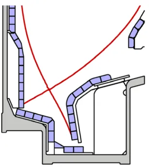
All modern tokamaks are constructed with a toroidal divertor, designed to isolate plasma-wall interactions and to spread heat loads over as broad an area as practical. C-Mod innovated the vertical target divertor shown in Fig. 3. The key features of this configuration are a shallow angle between the magnetic field (0.5-1.5 degrees, depending on the plasma equilibrium) and an extended divertor leg30,31. In this geometry, neutrals arising from recombination at the divertor strike point are directed toward the divertor channel, enhancing reionization and providing a natural baffling. Neutrals created in the divertor are isolated from the main chamber by the divertor plasma itself. One result is better isolation between the divertor and main plasma, leading to a lower density threshold for divertor detachment as discussed below. The advantages of the vertical target divertor are now widely recognized and the concept has been adopted for ITER.
B. Experience With a High-Z Metal First Wall
Also pioneered by C-Mod and adopted by ITER is the use of high-Z metals as a divertor material. C-Mod research has highlighted the advantages and the challenges of these materials and ultimately demonstrated their practicality. Any divertor material needs to withstand steady-state heat loads and to survive any transient loads that cannot be completely eliminated. In a reactor, operating with high availability for extended periods of time, two additional
requirements become critical. First, the net erosion rate must be held below 1 sputtered atom for every 106 incident plasma ions32,33. Second, for safety and limits in supply, the retention of tritium fuel must be kept very low – less than 1 atom of tritium fuel can be retained in the wall for every 107 plasma ions incident34,35. These requirements effectively rule out low Z materials like carbon even when they can withstand the heat loads. Graphite or carbon composites are a popular choice in current experiments because when introduced as an impurity into the plasma, the power loss from radiation is usually tolerable. High temperature plasmas consisting almost entirely of carbon ions, though useless for fusion, can be sustained. In contrast, the concentration of high-Z impurities must be strictly reduced – for example, concentrations of tungsten in ITER will need to be kept below 2x10⁻⁵ 36. Because refractory metals offered the promise to control erosion and fuel retention, but presented a severe challenge for impurity control, the C-Mod team felt that this was the correct choice – the fusion program would eventually have to step up to this challenge and C-Mod seemed like an ideal place to begin.
Experiments on C-Mod have addressed a large set of operational issues presented by the metal walls. These find no “show stoppers” that would rule out high-Z materials, but do reaffirm previous concerns about impurity sources and point out the need for additional research, particularly at the higher wall temperatures that will be typical of a fusion reactor. Plasma startup is not problematic with metal walls even after disruptions or other deconditioning events. This contrasts to the situation with carbon walls where some form of wall conditioning is typically required to reestablish operations37. Density control and fueling with metal walls are also straightforward, recycling is generally high, certainly well above 90% in equilibrium, with the walls adjusting to significant changes in a few shots, i.e. a few seconds of discharge time. In L-mode, the discharges can be readily gas fueled up to the density limit at currents up to 1 MA (
n
e= 6.5x10²⁰/m3). Access to H-mode is comparably easy, compared to carbon machines – for example at low q95, Ohmic H-modes are regularly attained38. The density in H-modes,
normalized to the density limit, is typically 0.5-0.7, a bit below that seen in lower field, neutral beam heated devices. The reason for this is that the very strong gas puffing required for higher densities interferes with ICRF antenna operation39, though the lack of beam fueling may also be a factor40 along with limitations of fueling and transport through a high-opacity edge and pedestal41. (The new field-aligned antenna described below in section VI has shown better behavior at very high neutral densities). Since fusion plasmas have much lower tolerance for high-Z impurities, control of the sources from the wall is critical, especially during ICRF. The first experiments with high power ICRF and bare molybdenum walls found sharply increased molybdenum content, increased core radiation and difficulty in achieving high quality H-modes42,17. It was not clear what parts of the vessel were the principal sources of these impurities. Boronization, as described above, was employed and had the effect of sharply reducing radiation from molybdenum43 and allowing the production of high quality H-modes17. Research on impurity challenges in ICRF heated plasmas is described in greater detail in section VI. Operational issues with tungsten plasma facing components are now also under intensive study by the AUG and JET devices44.
To keep the surface temperature of divertor plates within acceptable limits in a reactor, finite heat conduction dictates that no more than a few mm of material can intervene in front of the cooling channels. Thus net erosion must be kept on the order of 1 mm over the lifetime of the
first wall. One of the key advantages of refractory metals is their potential for lower levels of sputtering when exposed to ions (including impurities) accelerated through the plasma sheath. The energy threshold for sputtering from refractory metals is much higher than for low-Z materials like carbon or beryllium, with exponentially smaller sputtering yields if the edge plasma electron temperature can be held at sufficiently low values. Erosion rates for molybdenum was first determined on C-Mod by analysis of divertor tiles removed between experimental campaigns and measuring the change in depth of a thin chromium marker layer using Rutherford backscattering45. Net erosion was highest near the outer divertor strikepoint, reaching 150nm for the 1200 seconds of discharge time during the campaign, equivalent to removal of 4.5 mm/discharge-year. Gross erosion rates were estimated from physical sputtering yields using measured plasma conditions and were somewhat higher than the measured net erosion – partly attributed to prompt redeposition of sputtered ions. Installation of a toroidally continuous row of bulk tungsten tiles enabled measurement of erosion and migration onto other plasma facing components46. In this case the surfaces were analyzed after removal by measuring x-ray emission stimulated by exposure to a 2 MeV proton beam. Analysis of the x-ray spectra allowed determination of the quantity of tungsten on otherwise molybdenum substrates. Figure 4 shows the pattern of deposition found at different poloidal locations. The pattern suggests that scrape-off layer (SOL) flows play an important role in movement of sputtered materials to distant locations. Integration of migrated material yields an estimate for tungsten erosion of 0.014 nm/s or less than a mm per discharge-year - though we must note that the plasma strike-point was not in contact with the row of tungsten divertor tiles at all times during the experiments carried out in this campaign. The values for measured molybdenum and tungsten erosion were respectively 10 to 100 times lower than what has been found for graphite47. Gross erosion may be a more important measure of acceptable plasma-wall interaction since changes in surface morphology and chemistry associated with redeposition may lead to unacceptable changes in physical properties like thermal conduction. Gross erosion may also increase the amount of dust – a safety issue in a reactor – or allow the build-up of poorly bonded flakes which would subsequently enter the plasma and cause harmful disruptions.
The retention of tritium fuel within the first wall materials is another critical plasma-wall issue for ITER and for future reactors where safety considerations limit tritium inventory to about 1 kg. Using the expected plasma parameters, we find the acceptable limit is less than 1 tritium ion retained for every 107 incident on the plasma wall. A similar number is obtained from economic considerations, given the modest tritium breeding ratios that are expected. The requirement for low fuel retention also drives the interest in high-Z metal walls, since the solubility and reactivity of hydrogen in such metals is much lower than for carbon. Experiments on C-Mod measured retention of D2 gas over a single discharge by “static gas balance”, that is by looking at the
equilibrium pressure attained after running a plasma discharge with all torus pumps valved off compared to a case with the same gas puffing but without a plasma48. In these experiments roughly 1% of the incident deuterium ion fluence is retained with no indication that the retention rate is decreasing after 25 s of integrated plasma exposure. The magnitude of retention is significantly larger than what is expected from extrapolation of laboratory results49. The interpretation of the result is that “traps” are created in the molybdenum substrate by the high incident particle flux49. The traps are defects in the molecular structure that can hold deuterium atoms which are otherwise insoluble in the unperturbed matrix. In contrast to single shots, the
campaign-integrated retention is about 1000x lower. The difference is apparently due to the occasional disruption which removes deuterium through transient heating of the tile surfaces. These results point out the importance of conducting experiments at reactor-relevant temperatures, that is with the wall at about 1000 K, where defects in the wall molecular structure are expected to be annealed and retention is dramatically reduced.
An example of material changes that can be induced by plasma interactions is the growth of tungsten nano-structures (“fuzz”) that has been observed in plasma-wall test stands under suitable conditions50. The working hypothesis for their formation is that the structures, which consist of small filaments, are extruded by pressure from helium bubbles captured in the metal substrate. An open question was whether the same phenomena would occur on the wall of a confinement experiment or if other plasma-wall processes would destroy the structures before they could grow to significant size. On C-Mod, a careful experiment was performed to raise a tungsten sample to the correct surface temperature, about 2000˚K, and expose it to helium plasmas for a sufficient time to match the fluxes and fluences employed on the test stand. Nano-structures, shown in Fig. 5, were created with nearly identical morphology and growth rates (tendril diameter ~100nm and growth rate ~600nm in 13 sec of exposure at temperature)51,52. Helium concentrations in the fuzz layers were measured at 1 to 4%, which is well above natural solubility of helium in tungsten, but below the values expected for pressure-driven growth. Erosion rates from sputtering of the tungsten sample were well below the fuzz growth rate, however nearby molybdenum surfaces operating at lower temperatures were predicted to have faster sputtering than growth. As expected, these surfaces did not show evidence of surface nano-structures. Overall, we conclude that the tokamak environment has little or no impact on tungsten fuzz growth when compared to linear plasma devices. This provides confidence that key growth parameters identified in linear devices can be used to predict surface behavior in future devices. None-the-less, a number of critical questions must still be answered. Largely unknown are the effects of the fuzz on tokamak operations, including wall recycling, fuel retention, erosion and dust production. Research is also required to clarify the effects on fuzz growth of large ELMs, impurity seeding and mixed wall materials.
Post-campaign ex-situ measurements usually represent inadequately defined averages over discharge conditions from an entire campaign rather than carefully controlled conditions. A measurement from a single point in time is typically all that is available for an inherently dynamic and complicated process and progress is correspondingly difficult and slow. To overcome these limitations, a new diagnostic has been developed and deployed on C-Mod which is capable of time resolved, in-situ measurements of surface erosion and fuel retention. This diagnostic, AIMS (Accelerator Based in-situ Materials Surveillance), employs a 1 MeV D+ beam that is injected into the torus between shots and steered by the magnetic field produced by running small currents in the TF and PF coils53. A large selection of wall locations can be accessed by this method and tested between plasma discharges. The beam induces nuclear reactions that allow characterization of the surface composition. Some of the possible reactions and their application to surface analysis are listed in Table III. By preparing tiles with coupons of selected materials, the scope of possible measurements can be further increased, for example to measure the erosion of high-Z plasma-facing components. A drawing of the AIMS system is
shown in Fig. 6. Early results have proven the principle of the technique and show that measurements could be routinely made between shots54-56.
TABLE III. A few of the nuclear reactions that can be employed by the AIMS diagnostic
Probe ion Target Detected particle Surface measurement
D+ D n Fuel retention
D+ Li6, Be9, B11 γ Erosion of surface coating
D+ C12, N14, O16 γ Surface impurities
C. Divertor Regimes and Detachment Physics
Meeting the challenges of divertor power handling and erosion require better understanding of the underlying physics, through which improved designs and operating regimes can be achieved. The operating point of the divertor depends in large measure on the balance between parallel and perpendicular transport. Three regimes of parallel transport were identified in C-Mod experiments and are illustrated in Fig. 7, which compares electron pressure and temperature at the midplane to the corresponding profiles measured at the divertor target57,58. The midplane profiles are measured with fast-scanning Langmuir probes and the divertor profiles with fixed probes that are imbedded in the tiles. At the lowest densities, when the parallel electron mean free path is long compared to the connection length (~qR), electron temperature and pressure are constant along the field lines. The divertor sheath supports the entire temperature drop from the midplane to the tile surface. In this “sheath limited” regime, the divertor temperature is too high and would lead to unacceptable divertor erosion rates for a reactor. At moderate densities, collisions reduce the parallel thermal conduction and produce a parallel temperature gradient. This results in lower temperatures at the target, about 10 eV, and correspondingly lower erosion rates. The pressure along the field lines is still constant so the density increases near the divertor and supports the required power conduction. At higher densities still, the plasma interacts more strongly with neutrals (which increase nonlinearly with plasma density) transferring plasma momentum and energy to them. The momentum transfer causes the plasma pressure to drop and energy transfer lowers the temperature to the point where volumetric recombination occurs, further reducing the plasma pressure. In this “detached” stage the temperature at the target drops to about 2 eV and the heat is largely removed from the plasma by radiation and charge exchange, spreading the heat load over a much larger area. From the point of view of erosion and divertor survival it is highly desirable to operate the divertor in the detached state34.
The border between the three regimes can be characterized as fractions of the density limit, with the boundaries shifting to higher densities with increased input power. The density and power dependences are partly attributed to the increase in collisionality, consistent with the observations of anomalous cross-field transport discussed in section III.E. In typical SOL profiles, such as those shown in Figs. 7 and 8, detachment starts near the strikepoint first and grows outward as the density is raised. Experiments were carried out to explore the role of
divertor geometry in the detachment phenomena, comparing the standard vertical target configuration to a flat plate and slot divertor by moving the strike point across the divertor surfaces. Detachment occurred with the vertical target at about half the density of the flat plate with a slight further improvement for the slot divertor59. These experiments suggest that the main effect is an increase in the interaction between recycled neutrals and the divertor leg for the vertical target. The increase in divertor leg length is apparently a secondary effect. It is worth noting that detachment in C-Mod occurs well below the density limit for all three cases.
With the high plasma pressures that were accessible, C-Mod discovered the importance of volume recombination, neutral collisionality and Lyman α photon opacity on divertor behavior. Modeling of the ITER divertor has confirmed the importance of these parameters60. At the low temperatures and high densities seen in the detached regime the plasma can begin to recombine volumetrically, a process that otherwise occurs only on surfaces as recycling. Recombination was confirmed by the distribution of line intensities in the Balmer spectrum, which is markedly different in ionizing and recombining plasmas61,62. Extensive modeling of the spectra and atomic physics allowed determination of the recombination rate and of the plasma parameters in those regions. Under the conditions that prevailed, the plasma became opaque to Lyα photons62, with
the photon mean free path dropping to about 1 mm, modifying the recombination rate. Also affected by the operation at high densities is the transport of neutrals, with the mean free path for neutrals in C-Mod closer to what is expected in ITER than in any other device. Studies carried out to explore the dynamics and distribution of neutrals showed they are trapped in the divertor by the plasma, providing a natural baffling and building up the neutral pressure in the divertor chamber to levels exceeding 100 mT in some cases63,64. Recycling impurity gases are preferentially compressed and enriched in the divertor region65,66. Detachment can be enhanced by injection of impurities, which radiate inside the separatrix and in the divertor, reducing parallel heat exhaust. This effect can be exploited to reduce the divertor heat load, but care must be taken to avoid degrading core performance. The detachment front can be unstable along the field line and move to the x-point where the colder edge can reduce the H-mode pedestal. Modeling of the divertor region was carried out with the impact of each of these factors assessed67,68. Even with all of the known effects included, there were important experimental features that could not be modeled. The crucial missing physics may be the spatially dependent, nonlinear cross-field transport that is the subject of section III.E.
D. Divertor Heat Load
The heat load on the divertor is determined by the physics of the boundary plasma and the geometry of the magnetic field and first wall. While the process is simple to define, critical gaps in our understanding prevent reliable prediction and extrapolation to ITER and to future fusion reactors. C-Mod has carried out important research to help fill these gaps and to make direct measurements of the heat footprint under reactor-like conditions. The measurement of the heat load footprint is challenging on C-Mod for reasons very similar to those facing ITER. It is intrinsically hard to get a good view of the vertical target with an infra-red camera due to its geometry and the highly reflective metal walls have low emissivity. Moreover, the surface emissivity is not constant over time since changes in coatings or surface conditions are routine in the high heat-flux areas under study. To meet these challenges an innovative set of diagnostics
was deployed, summarized in Table IV and shown in Fig. 9, 69-73. The diagnostics targeted a region of the outer divertor that was modified to provide a slight radial ramp, ensuring that no tile-to-tile shadowing interfered with accurate measurements. Physics-based calibration strategies allowed redundant cross-comparisons adding to confidence in the results. A measure of success is that the overall energy accounting for each shot – power into the plasma vs power deposited on divertor and limiter surfaces – was balanced within 10% for discharges produced over the 3 years of experiments for which the diagnostics were in place74.
TABLE IV. Heat-flux footprint diagnostics
Diagnostic Measurement Analysis/Calibration scheme Reference
Langmuir probes Plasma Te, ne
Hat flux compared to surface thermocouples through sheath theory
72,73
Retarding field analyzer Plasma Ti
Compared to CXRS B5+ ion temperature 75,76 Surface thermocouples Instantaneous surface temperature and heat flux
Integrated and compared to calorimeters 73 Calorimeters Bulk temperature and integrated heat flux Ice-point compensated 72 IR Camera Instantaneous surface temperature Emissivity calibrated by
comparison with thermocouples imbedded in viewed tiles
69
A typical measurement of the heat footprint, mapped to the plasma midplane, is shown in Fig. 1077 which features the highest peak power and narrowest width of any existing device. Surface temperatures regularly exceed 1300˚K. The resulting data from C-Mod challenged empirical scalings that existed at the time78,79. Contrary to the earlier work, C-Mod found that the dominant scaling was 1/IP (or 1/BP) with no dependence on BT, q95, the connection length or on conducted
power71. Overall, the SOL power density profile at the divertor plate mapped to the pressure profile at the midplane – suggesting that critical gradient physics was responsible for setting the former quantity as well. The heat flux footprint was tied to pedestal conditions, consistent with the picture of the near-SOL and pedestal as a single integrated system. In L-mode and a variety of H-mode regimes, higher pedestal pressures are associated with narrower heat-flux footprints.
The higher pressure pedestals are also associated with better global energy confinement17 reinforcing the inherent challenge of achieving good core performance simultaneous with an acceptable divertor solution. C-Mod heat footprint data contributed to an international database, extending the range in BT, BP, plasma pressure and heat flux to ITER-like values in
multi-machine empirical scaling studies80. The unique diagnostic set on C-Mod also allowed an accurate determination of the sheath transmission factor that relates plasma properties upstream of the sheath to the heat flux conducted to the underlying material. Theoretical calculations predict a value for this factor ≈7, but experimental measurements of this critical quantity have ranged from 2-20 (with the values below 5, physically impossible). Using the measurements from the calibrated surface thermocouples and accounting for the non-zero current flowing through the sheath, good agreement with theoretical models was found, leading to an excellent match between the measured heat flux profile and the value calculated from probe measurements of the local plasma temperature and density (see Fig. 11)73.
Measurement of the divertor heat flux is only half the battle. Given the narrow deposition footprints that are currently predicted for ITER80, methods to reduce the power load to acceptable engineering limits must be found. One solution is to inject a small level of recycling impurities that would radiate near the plasma edge and spread the heat over a larger surface area. The challenge is to effect this change without reducing the heat flux across the separatrix and thus lowering the pedestal height and the overall plasma performance. Experiments were carried out to find the right types and quantities of impurity gas81. C-Mod was the first to demonstrate good core performance with Demo-like values of radiated power fraction. Using neon and nitrogen gases, these experiments were able to achieve H98 of 1 with conducted power to the
divertor normalized to the loss power (PLOSS = PIN-dWdt) as low as 10% as seen in Fig. 1282,83.
Interestingly the impurity seeding also improved ICRF coupling84. The effect is not understood but believed to be caused by changes in the edge plasma profiles or fluctuations.
E. Cross-field Transport and Flows in Boundary
C-Mod data have contributed to a new view of the nature and importance of cross-field transport in the tokamak boundary. Previously, transport in this region of the plasma had been assumed to be Bohm-like and poloidally symmetric (or often chosen arbitrarily and used as a free parameter to be adjusted to match models). Observations on C-Mod overturned this view, showing no dependence on BT and a strong dependence on collisionality85 – particle diffusivity is roughly
proportional to ν*2
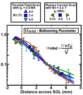
with profiles held near a critical gradient as explained by marginal stability arguments86,87. Figure 13 shows a set of SOL profiles for the normalized pressure gradient αMHD,
which is proportional to the βP gradient. This characterization of the profiles allows them to be
overlain for a wide range in operational parameters. The shape of these critical αMHD profiles is
consistent with a dependence on collisionality predicted by several theoretical treatments88,89. Fig 14 shows the increase of the normalized pressure gradient with normalized inverse collisionality in the regime of high collisionality87 and can be compared directly, for example, to Fig. 1 from reference89. The models predict a very sharp increase in turbulence and transport when the gradient exceeds some nominal threshold, thus enforcing the marginal stability condition. The measurements described here suggest that the SOL and pedestal should be treated as a single integrated system, and this continues to be an active and important area of C-Mod research.
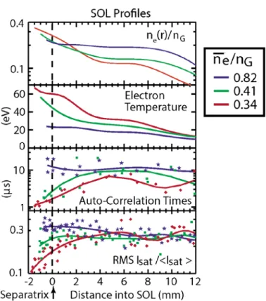
Turbulence and transport delineate two distinct regions of the boundary plasma. Typical profiles can be seen in Fig. 890. In the near-SOL, typically a few mm in C-Mod, the plasma gradients are steep and apparently determined by local marginal stability conditions as described above. Fluctuation statistics in this region are “normal”, that is with symmetric, Gaussian probability distributions86. Contrary to earlier expectations, the sharp gradients in the near-SOL profile shapes do not continue indefinitely (or until the plasma encounters a material object). Instead, after a relatively short radial distance, very large, isolated fluctuations are torn from the near-SOL and propagate radially due to uncancelled particle drifts into the “far-near-SOL” creating a region of relatively weak gradients91. These highly intermittent fluctuations, seen in ultra-high-speed images, Fig. 1592,93, are often referred to as blobs because of their appearance in poloidal cross-section or as filaments because of their extended structures along the magnetic field lines94. They cannot be understood from local plasma instabilities in the far-SOL – the gradients are too flat – but can be understood as the byproduct of near-SOL turbulence. Under these conditions, the plasma near the wall is not a vacuum and interactions with physical structures are inevitable. That is, the transport that leads to the flat profiles does not allow isolation of the plasma-wall interactions to the divertor as previously thought95. In particular, particle exhaust is not exclusively through the divertor leading to the phenomenon of “main chamber recycling”, first recognized on C-Mod. Rather than resulting only from leakage out of the divertor, a significant neutral population is built up in the vessel outer midplane through the interaction of the far-SOL and the wall. This result was most clearly demonstrated by the installation of a novel ‘divertor bypass flap’ system by which the divertor could be opened or closed during a C-Mod discharge96. With the divertor flaps open, neutral pressures in the divertor would decrease by a factor of two while midplane neutral pressured remained unchanged – that is, the pressure in the main chamber was set by its own dynamics not by leakage from the divertor97. These experiments also showed that divertor leakage had no effect on L-H power thresholds or H-mode confinement, contrary to prevailing ideas at the time. Blob dynamics have been compared to a variety of physical models which can, at least partially, explain their propagation velocity98,99. A statistical model has been developed, using measurements from C-Mod, that accurately describe the observed probability distribution function over many decades by characterizing the process with just two numbers – the birth duration and the average waiting time between blobs100-102. These numbers provide a sensitive metric for testing numerical models of near-SOL turbulence, whose dynamics should produce the same statistical quantities.
1. The Tokamak Density Limit as a Consequence of Edge Turbulence
Observations in C-Mod of anomalous cross-field transport in the plasma boundary also provide a likely mechanism for the tokamak density limit5,103 which has an empirical scaling nG = IP/πa2.
There is general agreement that the limit is associated with progressive cooling of the plasma edge, leading to a shrinkage of the current profile and Magneto-Hydro-Dynamic (MHD) instability. Unlike the operational limits on safety factor or pressure, the density limit cannot be understood solely through MHD mechanisms and despite its observation for more than 40 years, no definitive and self-consistent model for the limit has been developed. One class of models that was prevalent before the C-Mod results, explains the edge cooling as a consequence, in one way or another, of impurity radiation. These models are based on the explicit dependence of radiated power on plasma density and typically the dependence of radiation cooling curves on
temperature 104,105. However they fail to explain several important observations. First the density limit does not depend on input power, nor on impurity content (at least for discharges with ZEFF
< 2.5), neither is the limit always associated with very high levels of radiated power. Secondly, while Marfes and divertor detachment can occur near the limit, often they are triggered harmlessly at substantially lower densities106. An alternate mechanism, tied instead to changes in plasma transport, was motivated by observed changes in particle confinement near the density limit, the nonlinear increase in gas fueling required as the normalized density, n/nG, increased
and the observation that the decrease in density during current ramp-down at the end of a plasma shot, is often at the rate required to stay just below the density limit5. That is, the discharge sheds particles during ramp-down to keep n/nG just below 1.
C-Mod carried out experiments to measure the change in edge temperature along with any changes in fluctuations that accompany the approach to the density limit86,103. Well before the limit was reached, changes in the time-averaged SOL density profiles were observed, with progressive increases in the far-SOL density and overall flattening of the profiles even with modest increases in the separatrix density as shown in Fig 8. At the same time, the amplitude, frequency and velocity of blob production increased107,102. This picture is supported by fluid models which predict very strong transport under these conditions89,108. At still higher densities, the boundary between the near-SOL and far-SOL moved inward, with the region of colder plasma, intermittent fluctuations and blob creation109 eventually crossing the separatrix and intruding onto regions of closed field lines as seen in Figs 16 and 17. The net cooling mechanism is the exchange between warm plasma convected outward and cold fueling gas entering to replace it. When that boundary reaches roughly to the position of 0.85 normalized flux (a movement of about 3 cm on C-Mod), a density limit disruption is triggered. As the density limit is approached, perpendicular transport of energy is significantly increased and given the low upstream temperatures, the parallel energy transport channel is starved. This contrasts with the situation at lower density where all power is lost via the parallel channel to the divertor. In that case, the upstream temperature is pinned to a narrow range, typically to 60-100 eV, at the boundary between open and closed field lines. At densities close to the limit, perpendicular transport dominates on the open field lines and the temperatures can drop to much lower values. The appearance of Marfes or divertor detachment is then inevitable - if the plasma has not detached at lower densities, it will certainly detach near the limit where virtually no power is available in the parallel channel. While the observations coupled to the predictions of turbulence models make a compelling case for turbulence as the underlying cause of the density limit, work remains to develop a predictive model. What is required is a model that can calculate the change in the equilibrium temperature profile as the density is raised, which will require, at a minimum, a flux-driven solution to equations for turbulence and collisional plasma transport coupled to a neutral transport model.
2. Poloidally Asymmetric Transport and Sonic SOL Flows
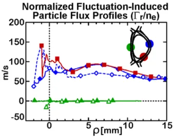
An important prediction of turbulence models is that transport would have a significant ballooning structure, that is the turbulence would be stronger on the low-field side of the plasma, which has bad curvature, compared to the high-field side with its good curvature. This prediction was tested on C-Mod using an innovative fast-scanning probe, mounted on the inner wall and
driven by the tokamak’s strong toroidal field crossed with currents in a small coil in the probe mechanism96,110. (The design is all the more remarkable in requiring that the probe be normally positioned in a protected location behind the inner-wall limiter, reducing space for the radial build for the entire mechanism to only 1 cm.) Fig 18 shows the normalized fluctuation induced particle flux profiles from several poloidal locations111. The flux is computed using the measured potential and density fluctuations, accounting for their phase difference and cross-correlation. The result is clear, there is virtually no turbulent transport on the high-field side of the tokamak as expected for modes driven by pressure and curvature. This is confirmed by observations of the profiles, which for the case of carefully balanced double null plasmas find almost no plasma on the high field side112. For single null plasmas, this region is populated, but only through parallel flows of plasma lost on the low-field side as shown in Fig. 19. The resulting flows can be measured and are found to be near the sound speed as the plasma expands into a near vacuum112. The effects of these flows on the H-mode threshold is discussed in section IV.A.
3. Impact of Cross-field Transport on Boundary Physics
Experimental results from C-Mod have highlighted the centrality of turbulent transport to a wide range of boundary plasma phenomena. These results challenged the conventional view that anomalous cross-field transport was a secondary effect that could be represented in a simplified parametric form in plasmas that were understood mainly through the lens of collisional transport and atomic physics. Particle exhaust was found to have an important perpendicular component, wherein the plasma-wall interactions could not be isolated to the divertor. The dynamics and thresholds for divertor regimes were found to be sensitive functions of perpendicular transport which not only competed with parallel processes but also determined the plasma-neutral interactions through the nonlinear increase in fueling required as the normalized density was increased. The same physics led to the tokamak density limit, which should be understood fundamentally as a transport phenomenon in which edge cooling is driven by collisionality-dependent turbulence. The poloidal asymmetry of turbulent transport, which is the result of curvature driven instabilities, causes sonic flows in the SOL. (We will see in the next section that these are likely responsible for important variation in the L-H threshold as well.) The width of the heat-load footprint, at least in the attached state, can also be understood as a manifestation of turbulent transport since the pressure profile at the target maps to the transport-determined midplane pressure. Overall, the conclusion must be that any prediction of plasma boundary and plasma-wall prediction requires deeper understanding of cross-field transport.
Fig. 3. The C-Mod vertical target divertor features a small incident angle between the magnetic field and the wall, a long divertor leg and natural baffling of neutrals. The separatrix for a typical MHD equilibrium is plotted in red.
Fig. 6. The AIMS diagnostic makes the first time-resolved, in-situ measurements of plasma-wall interactions. It utilizes a 1 MeV deuterium beam, which can be steered between shots by magnetic fields and induce nuclear reactions in the materials of the first wall. Fig. 5. A micrograph of tungsten nanostructures
produced by 13 s of helium discharge time on a target operating at about 2000K. The morphology and growth rate are essentially identical to what is produced in a linear plasma device under similar conditions.
Fig. 4. Tungsten redeposition thickness in nm, from a toroidal belt of tiles on the outer divertor (marked “W”). The material deposited can be integrated to estimate the average erosion rate.
Fig. 7. Three divertor regimes, that are produced at increasing density, are identified in this plot of pressure and temperature profiles in the SOL.
Fig. 8. Typical SOL density profile as a function of global normalized density.
Fig. 9. Divertor heat flux diagnostics
Fig. 10. The heat flux profile measured with the infra-red camera and calibrated against probes and thermocouples. These profiles show the narrowest width and highest power flux measured on any magnetic confinement experiment.
Fig. 12. Normalized H-mode confinement, H98 is plotted vs Pdiv/Ploss, the power conducted to the divertor normalized to the net input power. By puffing small amounts of impurities, radiation losses can be increased without degrading confinement - meeting ITER operational requirements.
Fig. 11. Heat flux profiles calculated based on plasma measurements compare well to the values taken directly from surface diagnostics.
Fig. 14. The normalized pressure gradient (αMHD) in the
near-SOL depends on strongly on collisionality. αd is the
inverse normalized collisionality as defined in Rogers 1998 PRL.
Fig. 13. Plasma profiles in the SOL overlay if they are parameterized by the αMHD
parameter (essentially the gradient in βP)
supporting the hypothesis that the profiles are set by cross field transport at marginal stability.
Fig. 15. The far-SOL plasma is composed of large amplitude structures (often called “blobs” or “filaments”) that originate in the near-SOL and propagate poloidally and radially. This image is produced by the gas-puff imaging (GPI) diagnostic.
Fig. 16. Edge temperature profiles show the progressive edge cooling as the normalized density is increased toward nG.
Fig. 17. Probe measurements show the increase in turbulence amplitude and intermittency that occurs as the normalized density ne/nG is raised.