Publisher’s version / Version de l'éditeur:
Vous avez des questions? Nous pouvons vous aider. Pour communiquer directement avec un auteur, consultez la Questions? Contact the NRC Publications Archive team at
[email protected]. If you wish to email the authors directly, please see the first page of the publication for their contact information.
https://publications-cnrc.canada.ca/fra/droits
L’accès à ce site Web et l’utilisation de son contenu sont assujettis aux conditions présentées dans le site LISEZ CES CONDITIONS ATTENTIVEMENT AVANT D’UTILISER CE SITE WEB.
IAHR'06, 2, pp. 185-192, 2006-09-01
READ THESE TERMS AND CONDITIONS CAREFULLY BEFORE USING THIS WEBSITE.
https://nrc-publications.canada.ca/eng/copyright
NRC Publications Archive Record / Notice des Archives des publications du CNRC :
https://nrc-publications.canada.ca/eng/view/object/?id=0896d97f-92e8-4342-85da-3aeabbc8015b https://publications-cnrc.canada.ca/fra/voir/objet/?id=0896d97f-92e8-4342-85da-3aeabbc8015b
This publication could be one of several versions: author’s original, accepted manuscript or the publisher’s version. / La version de cette publication peut être l’une des suivantes : la version prépublication de l’auteur, la version acceptée du manuscrit ou la version de l’éditeur.
Access and use of this website and the material on it are subject to the Terms and Conditions set forth at
Ice regime time-lines at Arctic structures: implications for evacuation
ICE REGIME TIME-LINES AT ARCTIC STRUCTURES:
IMPLICATIONS FOR EVACUATION
A. Barker, N. Durand and G.W. Timco
Canadian Hydraulics Centre, National Research Council, Ottawa, Ont., K1A 0R6 Canada
ABSTRACT
This paper presents the details of the ice conditions surrounding offshore caisson structures at different sites in the Canadian Beaufort Sea. This information is required as input for the design of suitable emergency evacuation systems from Beaufort Sea production structures. Reports from ice observers were reviewed and “time-lines” of the ice conditions were generated. There was a wide range of ice regimes at the sites. In some cases, large grounded rubble fields formed and were stable throughout the winter. At other sites, there was moving pack ice throughout the winter. Typically there were about 100 days of open water at each site. For the remainder of the year, ice surrounded the structure. These conditions must be taken into account in the design of suitable emergency evacuation systems.
KEYWORDS: Ice rubble, Beaufort Sea, grounded rubble, offshore structures, ice loads. INTRODUCTION
There is renewed interest in the oil and gas reserves in the Canadian Beaufort Sea. During the 1970s and 1980s, there was considerable exploration activity in this region and sizeable resources were found. Various types of systems were used as drilling platforms including floating drill-ships in deeper waters, bottom-based caisson structures in more moderate water depths (5 to 25 m), and artificial gravel islands in shallower waters. More recently, Devon Canada has drilled an offshore exploration well at the Paktoa C-60 site during the winter of 2005/06 using the steel caisson structure SDC. The exploration activity in this region has been done using seasonal drilling (i.e. drilling a well within one season of the year).
Emergency evacuation from structures in ice-covered waters can be problematic. This is a result of the large number of different ice conditions (or ice regimes) that can occur around the platform throughout the year (see Timco and Dickins, 2005). For seasonal drilling, this situation is somewhat easier and offshore rigs have at least two evacuation systems in place during the drilling process. For production structures with year-round activity, the platform will have to have additional systems, since not all systems can be used at all times (Timco et al., 2006).
For a production system, it is necessary to evaluate the potential ice regimes that the structure will encounter throughout the year and design evacuation and rescue systems that will have
the same level of safety regardless of the ice conditions surrounding the platform. This can be very challenging. During the autumn, the ice sheets can be quite open and mobile, and the launching of lifeboats will have to done carefully at a suitable distance from the platform to ensure that it does not get caught in the ice failing against the structure. During the winter, a grounded rubble field could surround the structure, and people could have to traverse this rubble during the evacuation process (this assumes that the preferred mode of evacuation, usually a helicopter, is not possible). If this was the case, an evacuation shelter (ES) can potentially be established at a safe distance on the ice for personnel until the rescue takes place. During the spring, the ice break-up would present a different set of challenges for evacuation and rescue, due to the melting and weakening of the surrounding ice as well as any rubble that may have formed. In this season, access to a structure by a rescue vessel can be hindered due to any remaining rubble, if suitable evacuation systems have not be designed to accommodate for this scenario.
This paper reviews previous offshore structures in the Canadian Beaufort Sea to develop “time-lines” that indicate the type of ice conditions that surround the platform throughout the year. This has been done by reviewing the environmental reports from a number of different platforms. This information is important for designers of emergency evacuation systems from offshore production structures in the Beaufort Sea.
PROCEDURE
The Canadian Hydraulics Centre of NRC has established a Centre of Ice-Structure Interaction (Timco, 1996). This Centre contains a large number of reports that were written during the intense exploration activity in the Beaufort Sea in the 1970s and 1980s. Many of the reports contain information on the ice conditions that surrounded a specific structure during the drilling season. The authors have used these reports to extract the details of the ice regimes around each of the four caisson structures (Tarsiut, SSDC, CRI and Molikpaq) that were used in the Canadian Beaufort Sea. There were, of course, different levels of detail available for each of the sites. Some sites contained very comprehensive information whereas others contained only general information. Over fifty reports were reviewed to extract the relevant details. Based on this, ice regime time-lines were developed for a number of sites. Table 1 lists the details for some of the sites that were studied. The following sections present information on three of these locations: the Kaubvik I-43, Tarsiut P-45 and Isserk I-15 sites.
Table 1: Details of the Caisson Locations in the Canadian Beaufort Sea. The seabed was subcut at the Isserk I-15 site (so the surrounding water depth is less than the water depth at the structure).
Location Structure Year WaterDepth
Water Depth to Berm/Seabed
Latitude Longitude
Tarsiut N-44 Tarsiut Caissons 1981 - 1982 21 6.5 69.896139 136.19347 Tarsiut N-44 TIRP Tarsiut Caissons 1982 - 1983 21 6.5 69.896139 136.19347
Uviluk P-66 SSDC 1982 - 1983 29 9 70.263444 132.31328
Kogyuk N-67 SSDC 1983 - 1984 28.1 9 70.113722 133.32822
Tarsiut P-45 Molikpaq 1984 - 1985 25.5 19.5 69.915444 136.418
Amauligak I-65 Molikpaq 1985 - 1986 31 19.5 70.077694 133.804556
Kaubvik I-43 CRI 1986 - 1987 17.9 9 69.875833 135.422028
Amauligak F-24 Molikpaq 1987 - 1988 32 13.8 70.054833 133.63025
Isserk I - 15 Molikpaq 1989 - 1990 11.5 13.4 69.91236 134.29922
Note that there is a range of water depths. In all cases but Paktoa and Isserk, a submarine berm was constructed before the structure was placed on site. This was necessary to bring the water depth locally in the range that could be safely used by the structure. At Paktoa C-60, the SDC rests on a barge, the MAT, while at Isserk I-15, the surrounding seabed was subcut for the placement of the Molikpaq. Figure 1 shows the locations of these sites.
Figure 1: Map showing the examined sites in the Canadian Beaufort Sea.
KAUBVIK I-43
The Esso Caisson-Retained Island (CRI) was used at the Kaubvik I-43 site during the winter of 1986-1987. This structure was developed as a means of reducing dredge quantities, as compared to the more traditional sand island. The CRI was built in 1982-83 and first deployed in the Canadian Beaufort Sea in the summer of 1983. It is an 8-segment octagonal-shaped steel structure about 118 m across on the flats, 12 m high and the outer face is inclined (30º from the vertical). The design has eight individual caissons (43 m long x 12.2 m high x 13.1 m wide) in a ring. Two pre-stressed bands of steel wire cable hold the caissons together. The central core, 92 m across, is filled with sand to provide a surface for drilling operations and to provide stability against applied loads.
The Kaubvik site is at the edge of the traditional edge of the landfast ice. Moving pack ice surrounded it, and thin first year ice acted directly upon the caissons. Since most storms approached from the northwest, the ice shear zone was driven towards the CRI from this direction. In October, rubble began to develop and ground around the structure, which continued developing into January. By February, a stable, grounded rubble field surrounded the caisson, and remained stable until May. Figure 2 provides information on the growth of the grounded rubble field at this site. Figure 3 shows a photograph of the structure with its attendant grounded rubble field and Figure 4 shows the time-line.
N
50 m
CRI - Kaubvik Open Water
First Year Pack Ice
Ice rubble on 5 January
First Year Pack Ice Open Water Grounded rubble on 4 Jan N 50 m CRI - Kaubvik Rubble on 6 January Rubble on 7 January Rubble on 12 January Late winter
rubble extent Landfast, level first year ice
Figure 2: Schematic illustration of the growth of the rubble field at the Kaubvik I-43 site.
Figure 3: Photograph of the CRI at the Kaubvik I-43 site, showing its extensive surrounding rubble field. October 21 substantial ice rubble started to form by caisson retained island. 2nd week of January
the Kaubvik site became landfast. The rubble field therefore stopped growing. The major accumulations of rubble occurred to the E and NW of the CRI. First week in October freeze-up usually starts. Middle of May maximum ice thickness of 2m is reached. End of January
maximum extent of the rubble field: 250m in the NW direction and 215m in the E direction. By midwinter the Kaubvik site is usually landfast. End of June spring break-up.
Figure 4: Time-line for the CRI at the Kaubvik I-43 site.
TARSIUT P-45
The Molikpaq structure was developed by Gulf Canada Resources Ltd. and operated by Beaudril, a subsidiary of Gulf. The Molikpaq is a Mobile Arctic Caisson (MAC), which was first deployed in the Canadian Beaufort Sea in 1984 and used for exploration drilling for four winter seasons in the Canadian Arctic. It consists of a continuous steel annulus on which sits a self-contained deck structure. The core of the annulus is filled with sand, which provides over 80 percent of the horizontal resistance. The outer face of the Molikpaq is designed for extreme ice features. The structure can operate without a berm in water depths ranging from 9 to 21 m. In water depths over this, the structure is designed to sit on a suitable submerged
berm. In deep waters, the angle of the outer face is 8º, whereas in shallower waters, the angle of the face is 23º.
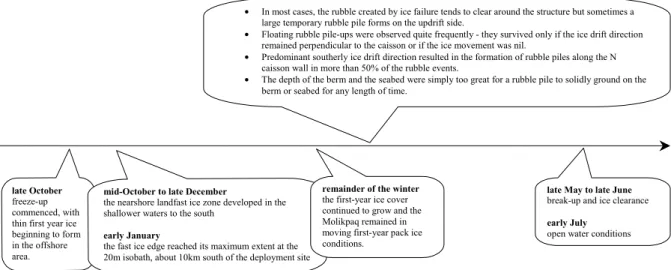
The Molikpaq was first deployed in 1984/85 at the Tarsiut P-45 site. This site, which is beyond the edge of the landfast ice, was in a water depth of approximately 25 m, so a small 5 m berm was built at the site. Figure 5 shows the Molikpaq at Tarsuit P-45 and Figure 6 shows the time-line for this site. There were direct first-year ice and old ice interactions with the near vertical caisson walls throughout the whole season. Events at the Tarsiut P-45 site were characterized by ice ride-up, pile-up and crushing at the vertical caisson faces. Rubble pile formation was initiated by flexural failure of the host ice sheet. This produced both floating and lightly grounded rubble piles. Rubble fields would form with a “prow” shape, never remaining for very long. Changes in the direction of the environmental driving forces would clear the rubble and often form a rubble field on another face.
Figure 5: Photograph of the Molikpaq at the Tarsuit P-45 site.
• In most cases, the rubble created by ice failure tends to clear around the structure but sometimes a large temporary rubble pile forms on the updrift side.
• Floating rubble pile-ups were observed quite frequently - they survived only if the ice drift direction remained perpendicular to the caisson or if the ice movement was nil.
• Predominant southerly ice drift direction resulted in the formation of rubble piles along the N caisson wall in more than 50% of the rubble events.
• The depth of the berm and the seabed were simply too great for a rubble pile to solidly ground on the berm or seabed for any length of time.
late October freeze-up commenced, with thin first year ice beginning to form in the offshore area.
mid-October to late December
the nearshore landfast ice zone developed in the shallower waters to the south
early January
the fast ice edge reached its maximum extent at the 20m isobath, about 10km south of the deployment site
remainder of the winter the first-year ice cover continued to grow and the Molikpaq remained in moving first-year pack ice conditions.
late May to late June break-up and ice clearance early July
open water conditions
ISSERK I-15
In 1989-90, the Molikpaq was used to drill a well for Esso, Gulf and Chevron at the Isserk I-15 site, in a water depth of 11.5 m. Since the water depth was relatively shallow, the ice interacted with the lower-sloped 23° face of the Molikpaq. During October and early November, the Molikpaq was exposed to mobile first year ice driven by strong winds. It was subjected to a series of storms that build a “cigar-shaped” rubble field at the site (see Figure 7). By November 10, however, the ice surrounding the Molikpaq had become quasi-stationary landfast ice. Figure 8 presents a time-line of the ice situation at the Isserk I-15 site.
Figure 7: Photograph showing the elongated rubble field at the Isserk I-15 site.
October 15 newly formed first-year sea ice first observed at Isserk October 23 - November 3
ice rubble fields formed during a series of ice movement episodes (lightly grounded) large rubble field grew to distance > 600m E of caisson November 4 no significant rubble growth was observed past this date
Until early October
Open water
Early October
Start of freeze-up
November 15
Average date for the onset of landfast ice
November 7
the ice sheet became landfast (ice thickness of about 40cm) November 10 landfast ice reached Isserk and surrounding rubble formation November 15 stable landfast ice N of caisson Late May maximum thickness of 1st
year ice cover ~1.8m
to January 27 (end of observations)
only minor ice movement observed February 10 cracks in the E rubble field that eventually dissected the field around the caisson Late June break-up began, with general ice clearance in early July Late June to early July
Landfast ice cover deteriorates, fragments, disperses offshore
Figure 8: Time-line showing the ice conditions at the Isserk I-15 site during the winter of 1989-1990.
SUMMARY
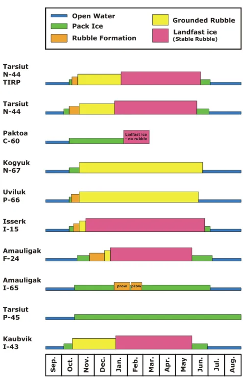
Figure 9 summarizes the results for the investigated Beaufort Sea sites. Details for all of the sites can be found in Barker et al. (2006). The figure shows a simple bar chart view of the ice conditions throughout the year that the structure was located at each site. Even though the Beaufort Sea is a relatively small geographic region, there is wide variation in the types of ice regimes encountered. This is a result of changes in water depth and the existence (or lack of) landfast ice at each site. Even at locations such at Tarsiut N-44, where data were available for more than one year, there is still variation in rubble formation, stabilization and break-up.
Open Water Rubble Formation Grounded Rubble Landfast ice (Stable Rubble) Tarsiut P-45 Amauligak I-65 Kaubvik I-43 Amauligak F-24 Isserk I-15 Uviluk P-66 Kogyuk N-67 Paktoa C-60 Tarsiut N-44 Tarsiut N-44 TIRP Apr . Oct . No v . Dec . Ja n . Fe b . Ma r. May Ju n . Jul . Aug. Se p . Ladfast ice - no rubble prow prow
Figure 9: Illustration of the ice regimes at various Beaufort Sea sites. As the Paktoa C-60 site was in exploration mode for 2005-2006, the timeline for this site cannot yet be completed. “Prow” indicates that while rubble formed, it only developed in the direction of ice loading. This type of rubble was usually dislodged with a change in ice loading direction. “Rubble Formation” refers to the initiation of floating or grounded rubble.
General information concerning average freeze-up and break-up dates etc. for various regions are available by looking at compiled ice atlases. However, detailed ice conditions at a site depend upon the water depth and the existence of landfast ice. The development of the detailed time-lines for these specific Beaufort Sea sites is enlightening when viewed from an emergency evacuation point of view, especially when considering the range of applicability of various evacuation systems. The time-lines show that there are typically about 100 days of
open water surrounding an offshore structure. Ice starts to form around the structure in early October and remains until July. The autumn pack ice period, defined here as the time from the formation of new ice until the formation of grounded rubble, could last as little as 16 days, or go throughout the winter, for those locations where there was no landfast ice. The spring break-up period, defined here from the initial break-up of the landfast ice until open water conditions, ranged from 8 to more than 30 days.
Early autumn storms can generate significant rubble that can ground in shallower waters or on berms. The grounding and subsequent development of a stable rubble field are interdependent upon both the water depth and the distance offshore. The former affects the initiation of grounding while the latter affects the time until the grounded rubble potentially becomes locked within landfast ice, thus stabilizing it against further significant movement. Once the landfast edge reaches the site during the winter season, these grounded rubble fields can be quite stable and evacuation onto them to an evacuation shelter (ES) can be a suitable option for emergency evacuation. As indicated in the bar charts, the period of time between rubble initiation and a stable rubble field can vary considerably, from a few days to never reaching a stable state, even though the rubble may be grounded. Generally, the rubble fields that developed in more shallow water depths (not depth to berm) remained stable for longer than those in deeper depths. At intermediate water depths, ice rubble can lightly ground but may not be suitable for evacuation platforms. Moreover, their existence may restrict or hamper using other options for evacuation such as an icebreaking supply vessel. In this case, the vessel would have to maintain a path to the structure to allow access for personnel in the event of an emergency. In deeper waters (such as Tarsiut P-45 or Amauligak I-65), the pack ice never reached a stable state where evacuation onto it would be a suitable evacuation option. It would be dangerous to venture onto the ice in these conditions.
This paper presents a brief summary of the ice conditions at a number of Beaufort Sea offshore sites. By creating time-lines that indicate the type of ice conditions that surround a platform throughout the year, it was observed that there could be a wide range of conditions even in this limited geographic region. Information on potential ice regimes at a site must be used as input into the design of suitable evacuation systems for any production platform designed for this region. All potential ice conditions must be considered to produce a safe, year-round emergency evacuation system from an offshore production structure.
ACKNOWLEDGEMENTS
The authors would like to acknowledge the funding this work from the Climate Change Technology and Innovation Initiative (CCTII) and the Program of Energy Research and Development (PERD) through the Marine Transportation Safety POL.
REFERENCES
Barker, A., Timco, G.W. and Durand, N. (2006). Time-lines of Ice Conditions for Offshore Structures in the Canadian Beaufort Sea. CHC/NRC Technical Report (in preparation), Ottawa, Canada.
Timco, G.W., Wright, B.D., Barker, A. and Poplin, J.P. (2006). Ice Damage Zone around the Molikpaq: Implications for Evacuation Systems. Cold Regions Science and Technology 44, pp 67-85. Timco, G.W. and Dickins, D.F. (2005). Environment Guidelines for EER Systems in Ice-Covered Waters. Cold Regions Science and Technology 42, pp 201-214.
Timco, G.W. (1996). NRC Centre of Ice/Structure Interaction: Archiving Beaufort Sea Data. Proceedings 13th IAHR Symposium on Ice, Vol. 1, pp 142-149, Beijing, China.