Publisher’s version / Version de l'éditeur:
Vous avez des questions? Nous pouvons vous aider. Pour communiquer directement avec un auteur, consultez la
première page de la revue dans laquelle son article a été publié afin de trouver ses coordonnées. Si vous n’arrivez pas à les repérer, communiquez avec nous à PublicationsArchive-ArchivesPublications@nrc-cnrc.gc.ca.
Questions? Contact the NRC Publications Archive team at
PublicationsArchive-ArchivesPublications@nrc-cnrc.gc.ca. If you wish to email the authors directly, please see the first page of the publication for their contact information.
https://publications-cnrc.canada.ca/fra/droits
L’accès à ce site Web et l’utilisation de son contenu sont assujettis aux conditions présentées dans le site LISEZ CES CONDITIONS ATTENTIVEMENT AVANT D’UTILISER CE SITE WEB.
Internal Report (National Research Council of Canada. Division of Building
Research), 1971-03-01
READ THESE TERMS AND CONDITIONS CAREFULLY BEFORE USING THIS WEBSITE.
https://nrc-publications.canada.ca/eng/copyright
NRC Publications Archive Record / Notice des Archives des publications du CNRC :
https://nrc-publications.canada.ca/eng/view/object/?id=18a28739-2815-4047-88a9-d614bb308ac7 https://publications-cnrc.canada.ca/fra/voir/objet/?id=18a28739-2815-4047-88a9-d614bb308ac7
NRC Publications Archive
Archives des publications du CNRC
For the publisher’s version, please access the DOI link below./ Pour consulter la version de l’éditeur, utilisez le lien DOI ci-dessous.
https://doi.org/10.4224/20331657
Access and use of this website and the material on it are subject to the Terms and Conditions set forth at
Performance of insulations located above an impermeable membrane
in a flat roof system
NATIONAL RESEARCH COUNCIL OF CANADA DIVISION OF BUILDING RESEARCH
PERFORMANCE OF INSULATIONS LOCATED ABOVE AN IMPERMEABLE MEMBRANE IN A FLAT ROOF SYSTEM
by
C. P. Hedlin, D. G. Cole, and G. O. Handegord
Internal Report No. 386 of the
Division of Building Research
OTTAWA
March 1971 .-,
PREFACE
The impermeable membrane of a flat roof can be protected from solar radiation, the effects of extreme temperature variation, and from traffic damage by placing it beneath the roof insulation. This provides the membrane with a better chance of performing its function of protecting the building from the entry of moisture. Now, however, the insulation is exposed to the weather and may lose its thermal insulating properties by becoming wet. Using experimental facilities which permit exposure of materials to outdoor conditions, several insulations - both porous and closed cell - were incorporated into a roof system of this type. Moisture contents and thermal conductances were measured periodically over a span of about two years. The results are reported here. This is being followed by work involving similar measurements with other design arrangements.
N. B. Hutcheon Director
Ottawa March 1971
PERFORMANCE OF INSULATIONS LOCATED ABOVE AN IMPERMEABLE MEMBRANE IN A FLAT ROOF SYSTEM
by
C. P. Hedlin, D. G. Cole, and G. O. Handegord
Flat roof systems usually include a deck for support, insulation to limit heat flow, an impermeable membrane to prevent entry of water from the outside and, possibly, a vapour barrier to prevent entry of moisture into the roof covering from the inside. Traditionally, the insulation has been placed on the
deck and an impermeable membrane of several layers of felt and bitumen placed on top of it to protect the insulation and the building below from water leakage. The membrane is the key to the performance of the roof covering. This relatively fragile component experiences extremes of temperature, which may range from -40 to
+
150F or more in Canada, solar radiation if the gravel layer is disturbed, and wear by traffic. If failure of the membrane occurs at any point, the entire roof covering may fail. Further, moisture inadvertently sealed into the roofsandwich during installation, or subsequently entering it from below, may result in deterioration of the membrane and the insulation, and eventual failure. I
The high incidence of such failures has led to consideration of other designs which would avoid the weaknesses inherent in the conventional system. One such design reverses the position of the insulation and the membrane, placing the membrane on the deck and the insulation on top of it. In this arrangement, the fluctuations in temperature of the membrane are very much reduced, and its protection from solar radiation and traffic is assured. However, the insulation is now placed in an exposed location where rain and melting snow may wet it, and some means of protecting it from solar radiation and mechanical damage must be devised.
In 1966, an opportunity was provided at the Outdoor Experiment Station, DBR Prairie Regional Station. Saskatoon, to observe the
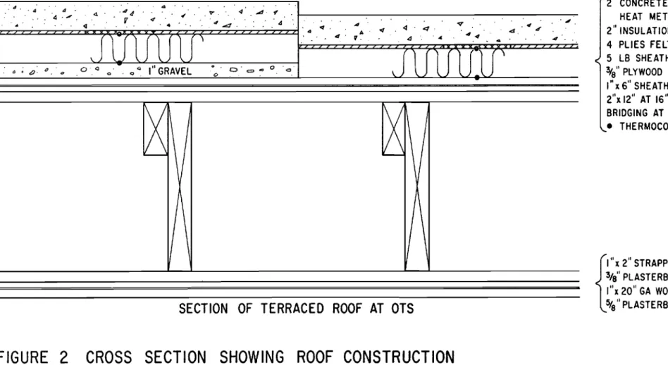
performance of several materials in such a design. A section of roof, 20 ft by 47 ft having the basic structure as shown in Figure 2, was covered with a 4-ply organic felt-asphalt roof membrane. The roof slope averaged about 1/4 in. per foot.
2
-On one half of the roof (10ft by 47 ft), a 1 -in. layer of gravel was placed above the membrane to provide for water drainage to the
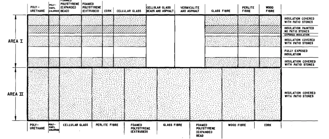
gutters. Rigid forms of polyurethane (two types). polyvinyl chloride, cellular glass, perlite, foamed polystyrene (two types), glass fibre, wood fibre. and cork insulations were used. They were held in place by 2- by 24- by 24-in. concrete paving stones (area II, Figure 1).
Heat meters were placed on the deck under the gravel at selected locations, and pairs of thermocouples were placed, one above and the other below the insulation. in conjunction with thes e heat meters. The measurement of heat flow and temperature
differential were intended for use in measuring the apparent thermal conductances of the insulations. Air movement in the gravel caused such wide fluctuations in the meter readings that meaningful measure-ments could not be made. Consequently, the gravel at the heat meter locations was removed and the corresponding piece of insulation was lowered so that it was in contact with the deck. As a result, some insulation boards rested on the deck and others of the same type remained on the gravel,
The same insulations were placed on the other 10- by 47 -ft section of the roof. but in this case there was no gravel; paving stones covered only three-fifths of the insulation surface. about one fifth was painted, and the other one fifth was fully exposed (area I. Figure 1).
RESULTS
During the period 1966 -1969, the moisture content of the insulations under the paving stones was measured periodically by weighing a removable piece of the insulation. High moisture
contents existed in all but cellular glass and the foamed polystyrenes (Table I). In general, the samples on the deck had a somewhat higher moisture content than those on the gravel, The values for most samples were markedly higher in October of 1968 than in October of 1967. possibly because of the exceptionally wet autumn in 1968.
Table I contains a series of moisture measurements. The
results should not be used to plot moisture changes with time, however, as irregularities caused by rainfall, snow melt. and drying periods
are not necessarily reflected in these spot measurements. Consequently, generalizations as to time-moisture content based on them are of
3
-dubious accuracy. They may be regarded as useful indications of moisture content but cannot be used to estimate seasonal variations.
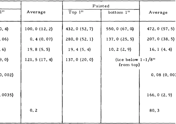
Core samples of painted and exposed insulations were taken to determine their moisture content (Table II). Average values for unpainted insulations (exclusive of the polystyrenes and foam glass), ranged from O. 4 per cent for perlite to 120 per cent for
glass fibre. With the exception of fibreboard and foamed polystyrene, the painted sections were much wetter than the unpainted ones.
During the winters of 1967 -1968, thermal conductances of insulations lying on the deck under the paving stones were measured, using the heat meters originally installed (Table III). In the
1968 -1969 season, conductances were measured using a pair of heat meters that could be moved as required. Measurements were made simultaneously for insulation on gravel and the same insulation on the deck. A meter was placed on top of the insulation and covered with a paving stone to pr event the disturbing effect of air flow. A mask of the same thickness as the heat meter occupied the rest of the area under the paving stone. The tabulated values were derived from hour -long averages, taken toward the end of periods of steady conditions, or 24-hour averages of recorded data. These, along with thermal conductivities for dry materials taken from tables in the ASHRAE Handbook of Fundamentals, are given in Table III. The conductances for the foamed polystyrenes were approximately the same as the thermal conductivity for the dry material. Cellular glass was not tested. For all the other insulations, the observed values were much higher than the dry conductivities. The ratios ranged from 20 to 1 for perlite to 5 to 1 for cork. The moisture content in 1968-1969 was much higher than in 1967-1968, but there was not a corresponding difference in the conductance.
Tables I and III contain results of moisture content and heat flow measurements. Readers are cautioned against attempting to correlate the moisture content with heat flow for corresponding insulations, since the measurements were not made at the same time or at the same location in the insulation.
The gravel under the insulation constitutes a permeable layer through which cold air may flow due to the effect of wind pressure. Any such flow would carry away heat coming through the roof structure and cause a reduction in the warm -side temperature of the insulation.
4
-In the most extreme condition, all of the heat would be removed, thus reducing the warm -side temperature of the insulation to that of the outside air, and completely nullifying its effect. Some evidence of the magnitude of this effect can be obtained by comparing the temperature differentials across foamed polystyrenes on the deck with those on gravel, thus using them as crude heat meters to assess the heat flow. For the bead-type polystyrene, the warm side on the deck averaged about 1/2 F degree warmer than that on the gravel. For the cellular type, the difference was about 2 F degrees. These differences in temperature suggest that nearly the same amounts of heat were flowing through the insulation whether on gravel or on the deck, and hence the amount lost by ventilation of the gravel layer was not large.
SUMMARY
The thermal performance of the foamed polystyrene used in this particular roof system showed little departure from that of the normal dry material; only moderate increases occurred in their moisture contents. Although the heat flow through foamed glass was not measured, its moisture content also remained low. All the other insulations retained large amounts of moisture when under paving stones, and had high thermal conductances. The reduction of insulating value was so great that their use in this particular roof design must be considered impractical.
On the basis of a single set of observations, the insulations retained varying amounts of water when painted, and relatively little when exposed. This suggested that the effect of an open upper surface may offset the effect of increased exposure to rain and
snow cover, at least under the weather conditions of this experiment. These results are for a particular design of roof system nearly flat with paving stones resting directly on the insulation -and do not constitute complete information on the subject. It is only part of an investigation that is intended to provide information about the performance of a variety of insulations in different designs, including varying top cover and deck slope. Preliminary results, some of which are included here, suggest that some insulations that performed poorly in this experiment may do better under more favourable design conditions.
5
-REFERENCES
1. Handegord, G. O. and M. C. Baker. Application of Roof Design Principles. National Research Council of Canada, Division of Building Research, Ottawa. Canadian Building Digest No. 99, March 1968.
2. Building Research 1966, p. 57 -61. (Annual Report of the Division of Building Research) NRC 9573.
TABLE I
MOISTURE CONTENTS OF INSULATIONS UNDER PAVING STONES
%
by dry weight(%
by volume)Dry Aug. 29/ Oct. 10/ Dec. 8/ Mar. 4/ June 3/ Oct. 21/ Apr. 16/ density
67 67 67 68 68 68 69 Ib ft3 Cork G>:' 15.1 (1.6) 22. 5 (2. 7) 34.1 (4.1) 42. 4 (5. 2) 30. 4 (3. 7) 108.6 (13.3) 40.8 (5. 0) 7.6 D'O'»e- 44.8 (5. 5) 26.9 (3.3) 36.7 (4.5) 47.2 (5.7) 94. 8 (11. 5) 199.0 (24.4) 228.0 (28. O) Perlite G 9.2(1.7) 11.1(2.1) 47. 1 (8. 8) 56.5 (10.5) 105.0 (19.5) 381.0 (71.0) 11. 6 D 84.9 (15.8) 24. 4 (4. 5) 143.4 (26.6) 275. 2 (51. 1) 330.0 (61. 4) 289.0 (54. 0) Wood fibre G 69.4 (19.2) 24. 5 (6.8) 30. 5 (8. 5) 42.6 (11. 8) 115.0 (31. 9) 277.0 (77.0) 17.3 D 29.4 (8.1) 10.3(2.9) 13.8 (3. 8) 11. 5 (3.2) 219. 0 (61. 0) Glass fibre G 57.5 (8. 3) 20. 5 (3. O) 74.0 (10. 8) 40.0 (5. 8) 157.0 (23. O) 66. 4 (9. 7) 9. 1 D 249.0 (36.3) 151. 0 (22. O) 354.0 (51. 8) 27 6. 0 (40. 3) 371. 0 (54.0) 290. 0 (42. 4) Cellular 5.9(0.8} 29. 6 (4. 3) 15.4(2.2} 15.3 (2. 2) 9.0 glass Foamed G 2.9 (0. 11) 3. 1 (0. 11) 19.1 (0.70) 3.1 (0.11) 24.9 (0.92) 20.0(0.74) 2. 3 polystyrene D 3.7 (0.14) 1. 5 (0.05) 20. 1 (0. 74) 12.1 (0.45) 33.7 (1. 2) 31. 0 (1. 1) (cellular type) Foamed G 0.7 (0.012) 1. 0 (0. 018) 7.9 (0.14) 2.0 (0. 035) 20. 5 (0. 36) 28. 6 (0. 5) 1.1 polystyrene D 25. 7 (0. 45) 11.8(0.21) 23.8 (0. 42) 10.0(0.18} 68.2(1.2} 201.0 (3. 5) (bead type) Polyurethane G 50. 7 (1. 5) 105.0 (3.2) 410.0
u
z.
5) 234.0 (7. 1) 597.0 (18.2) 424. 0 (12. 9) 1.9 D 2.8 (0. 08) 94. 0 (2.9) 440. 0u
s.
4) 66.0 (20. 2) 1001. 0 (30.5) 1113.0 (34. O) Polyurethane G 6. 1 75.0 29.9 85.0 58.0 (Purl) D 17. 7 120.0 124.0 258.0 103. 0 Polyvinyl G 5.6 192.0 81. 0 99.0 725.0 chloride D セPUNP 218. 0 265.0 464.0 915.0TABLE II
MOISTURE CONTENTS OF INSULATIONS NOT COVERED WITH PAVING STONES
0/0
by dry weight(0/0
by volum e)Unpainted Painted
Top 1" bottom 1" Average Top 1" bottom 1" Average
-Cork 43. 5 (5.3) 168.0 (20.4) 100.0 (12.2) 432. 0 (52. 7) 550. 0 (67.0) 472.0 (57.5) Perlite O. 4 (0.07) 0.3 (0. 06) O. 4 (0.07) 280.0 (52.1) 137.0 (25.5) 207. 0 (38. 5)
Wood fibre 30.2 (8.4) 9.4(2.6) 19.8 (5.5) 19.4 (5.4) 10.2(2.9) 16.1 (4.4)
Glass fibre 112.7 (16.4) 130.4 (19.0) 121, 5 (17. 4) 137.0 (20.0) (ice below 1-1/8" from top) Foamed polystyrene O. 06 (0. 002) 0.06 (0.002) O. 08 (0.00 (cellular) Foamed polystyrene O. 2 (0.0035) O. 2 (0. 0035) 166.0 (2.9) (bead) Polyurethane O. 2 80. 3 (Purlboard) 3)
TABLE III
CONDUCTANCE AND HEAT FLOW FOR INSULATIONS UNDER PAVING STONES
Conductance Thermal conductivity
Insulation Date Btu/hr sq ft 0 Fin. of dry insulation on deck over gravel Btu/hr sq ft
0 Fin. Cork 1/68 0.76 0.26 12/68 1.2 1.1 3/69 1.2 1.0 Perlite 1/68 8. 1 O. 36 12/68 6. 1 5. 1 3/69 6.0 2.8 Perlite (fully 0.55 exposed. no paint, no paving stone) Wood fibre 12/68 1.2 2.0 0.42 3/69 3.6 3.2 Glass fibre 1/68 3. 7 0.22 12/68 2.4 1.0 3/69 4.4 0.9 Foamed 1/68 0.23 0.24 polystyrene 12/68 O. 21 O. 19 (cellular) Foamed 1/68 0.30 0.26
pol ystyr ene 11/68 0.34 0.28
(bead)
Pol yur ethane 1/68 0.48 0.17
12/68 2.8 0.9
Ice 12.0
セ
po lyM
I
セセセセrene
I
FOAMEDI
I
I
POLY - YINYL (EXPANDED POLYSTYRENE CELLULAR GLASS
URETHANE HLORIOE BEAD) (EXTRUDED) CORK
I
CELLULAR GLASS BEADS AND ASPHAlTVERMICULITE
AND ASPHALT GLASS FIBRE
I
p..ERLITEFIBREI
WOOD
FIBRE
INSULATION COVERED WITH PATIO STONES EXPOSED INSULATION INSULATION COVERED WITH PATIO STONES INSULATION PAINTED NO PATIO STONES
セ
NZセ|ZZエセセOZOZH
c_[セZL_Q「セ[サZZ|uZᄋj[ZᄋN|スRスNサ[IセセNA
AOゥxセIhスONZ[_[NゥOセZZ[ZtlAZxᄋセᄋセZセエ\Q_RAヲhィH_i⦅
AR[
ZセZZ\| 」LセLセLZ ZZOセZZZZG」ZZZᄋ ョセZ[ZBZZZZ 」セGZZZZ[ZZセZ[LGZZZ
};;:;,
ョᄋスエIイI{ャセ|ャョスセI{fusXゥRエ\ysjAOcセセ||OZスAZZセヲAセZZGZサᄋZ||サ
N[ セN
... '" :GZZZセ[ZNZZBN[ZZj
;':-:.:::::.,:J ..:-.,..
IGN[[セ セ イ|スᄋセHZセセZZMQゥ
_|セ_ZZサIスhエエhャ||ZMI_セGZGB
FULLY EXPOSED INSULATION INSULATION COVERED WITH PATIO STONESAR INSULATION COVERED
WITH PATIO STONES
セ
y M セ
POLY- YIIYL
I
URETHANE CHLORCELLULAR GLASS
I
PERLITE FIBREI
FOAMEDI
GLASS FIBREI
FOAMEDI
WOOD FIBREI
CORKI
POLYSTYRENE POLYSTYRENE
(EXTRUDED) (EXPANDED
BEAD
FIGURE
ARRANGEMENT OF INSULATION
IN EXPERIMENTAL FLAT ROOF SYSTEM
.. d . ... 4 ' 4 4 , 4 4 9", At! セ <I "
"
セ ' , I " , V 4' "-:1 <I...
セ <1."<1,,..
4 . ...
<f, <t 4 4..
A "".,J
1
J'
.,
'1. 4..
..
...
,
\. O'Q '" 1" GRAVEL.
, oᄋセ <10 0 <:l \ t:) • p. a a 0 ' q CoSECTION OF TERRACED ROOF AT OTS
FIGURE 2
CROSS SECTION SHOWING ROOF CONSTRUCTION
8/14686-1
2" CONCRETE PATIO SLAB
HEAT METER AS USED 1968-69 2" INSULATION
4 PLIES FELT AND ASPHALT 5 LB SHEATHING PAPER
3tg"PLYWOOD
I"
X6" SHEATHING2"x 12" AT 16"O.C. WITH 2"x
2"
CROSSBRIDGING AT 6'-0" O.C. MAX • THERMOCOUPLE LOCATION
{
I" X2" STRAPPING AT 16"0.C. 3fs"PLASTERBOARD
I"x 20" GA WOVEN WIRE MESH 5fa"PLASTERBOARD