Publisher’s version / Version de l'éditeur: Transport Canada Report, 1999-05-01
READ THESE TERMS AND CONDITIONS CAREFULLY BEFORE USING THIS WEBSITE.
https://nrc-publications.canada.ca/eng/copyright
Vous avez des questions? Nous pouvons vous aider. Pour communiquer directement avec un auteur, consultez la
première page de la revue dans laquelle son article a été publié afin de trouver ses coordonnées. Si vous n’arrivez pas à les repérer, communiquez avec nous à [email protected].
Questions? Contact the NRC Publications Archive team at
[email protected]. If you wish to email the authors directly, please see the first page of the publication for their contact information.
NRC Publications Archive
Archives des publications du CNRC
Access and use of this website and the material on it are subject to the Terms and Conditions set forth at
Airfoil-flap performance with de/anti-icing fluids and freezing
precipitation
Oleskiw, Myron M.; Penna, Paul J.
https://publications-cnrc.canada.ca/fra/droits
L’accès à ce site Web et l’utilisation de son contenu sont assujettis aux conditions présentées dans le site LISEZ CES CONDITIONS ATTENTIVEMENT AVANT D’UTILISER CE SITE WEB.
NRC Publications Record / Notice d'Archives des publications de CNRC:
https://nrc-publications.canada.ca/eng/view/object/?id=896bab91-f27b-4d35-9910-eb3f126f1eb9 https://publications-cnrc.canada.ca/fra/voir/objet/?id=896bab91-f27b-4d35-9910-eb3f126f1eb9
Airfoil-Flap Performance with De/Anti-icing
Fluids and Freezing Precipitation
TP 13426E May 1999
Prepared for
Transportation Development Centre
Safety and Security
Transport Canada
by
National Research Council Canada
Institute for Aerospace Research
Aerodynamics Laboratory
Ottawa, Ontario
Government Gouvernement
TP 13426E
Airfoil-Flap Performance with De/Anti-icing
Fluids and Freezing Precipitation
by
Myron M. Oleskiw and Paul J. Penna National Research Council Canada
Institute for Aerospace Research Aerodynamics Laboratory
Ottawa, Ontario
ii
This report reflects the views of the authors and not necessarily those of the Transportation Development Centre.
The Transportation Development Centre does not endorse products or manufacturers. Trade or manufacturers’ names appear in this report only because they are essential to its objectives.
Transport
Canada TransportsCanada
PUBLICATION DATA FORM
1. Transport Canada Publication No.
TP 13426E
2. Project No.
8937/9034 (DC 140)
3. Recipient’s Catalogue No.
4. Title and Subtitle 5. Publication Date
May 1999
6. Performing Organization Document No.
7. Author(s)
Myron M. Oleskiw and Paul J. Penna
8. Transport Canada File No.
ZCD2450-B-14
9. Performing Organization Name and Address 10. PWGSC File No.
11. PWGSC or Transport Canada Contract No.
12. Sponsoring Agency Name and Address 13. Type of Publication and Period Covered
Final
14. Project Officer
Barry B. Myers
15. Supplementary Notes (Funding programs, titles of related publications, etc.)
Co-sponsored by the National Research Council Canada/Institute for Aerospace Research (NRC/IAR)
16. Abstract
17. Key Words
Aerodynamic behaviour, airfoil, de/anti-icing fluids, wind tunnel tests
18. Distribution Statement
Limited number of copies available from the Transportation Development Centre
19. Security Classification (of this publication)
Unclassified
20. Security Classification (of this page)
Unclassified 21. Declassification (date) — 22. No. of Pages xii, 14 23. Price Shipping/ Handling CDT/TDC 79-005 Rev. 96 iii
Air-Flap Performance with De/Anti-icing Fluids and Freezing Precipitation
National Research Council Canada Institute for Aerospace Research Aerodynamics Laboratory Ottawa, Ontario
K1A 0R6
Transportation Development Centre (TDC) 800 René Lévesque Blvd. West
Suite 600
Montreal, Quebec H3B 1X9
The aerodynamic performance behaviour of contaminated de- and anti-icing fluids was observed in the National Research Council Canada’s 3 m x 6 m open circuit wind tunnel. The airfoil tested was a full-scale (1.8 m chord), NASA LS(1)-0417 section with a Fowler flap deployed at 15 degrees. A spray bar located in the wind tunnel settling chamber produced artificial winter precipitation. Takeoff was simulated by accelerating the test section wind speed. Aerodynamic data were obtained while pitching the airfoil to stall. The tests showed that lift loss associated with contamination of de- and anti-icing fluids on the airfoil increased rapidly once the fluids could no longer absorb the freezing precipitation. The contamination periods required to reach the visual and aerodynamic failure of the fluid were generally consistent with the Society of Automotive Engineers (SAE) standard holdover times that corresponded to the test conditions.
Transports
Canada TransportCanada
FORMULE DE DONNÉES POUR PUBLICATION
1. No de la publication de Transports Canada
TP 13426E
2. No de l’étude
8937/9034 (DC 140)
3. No de catalogue du destinataire
4. Titre et sous-titre 5. Date de la publication
Mai 1999
6. No de document de l’organisme exécutant
7. Auteur(s)
Myron M. Oleskiw et Paul J. Penna
8. No de dossier - Transports Canada
ZCD2450-B-14
9. Nom et adresse de l’organisme exécutant 10. No de dossier - TPSGC
11. No de contrat - TPSGC ou Transports Canada
12. Nom et adresse de l’organisme parrain 13. Genre de publication et période visée
Final
14. Agent de projet
Barry B. Myers
15. Remarques additionnelles (programmes de financement, titres de publications connexes, etc.)
Projet coparrainé par le Conseil national de recherches du Canada et l’Institut de recherche aérospatiale (CNRC/IRA)
16. Résumé
17. Mots clés
Comportement aérodynamique, surface portante, fluides dégivrants/antigivrage, essais en soufflerie
18. Diffusion
Le Centre de développement des transports dispose d’un nombre limité d’exemplaires.
19. Classification de sécurité (de cette publication)
Non classifiée
20. Classification de sécurité (de cette page)
Non classifiée 21. Déclassification (date) — 22. Nombre de pages xii, 14 23. Prix Port et manutention CDT/TDC 79-005 Rev. 96 iv
Air-Flap Performance with De/Anti-icing Fluids and Freezing Precipitation
Conseil national de recherches du Canada Institut de recherche aérospatiale
Laboratoire d’aérodynamique Ottawa, Ontario
K1A 0R6
Centre de développement des transports (CDT) 800, boul. René-Lévesque Ouest
Bureau 600 Montréal (Québec) H3B 1X9
Des essais ont été réalisés dans la soufflerie à boucle ouverte de 3 m x 6 m du Conseil national de recherches du Canada, pour étudier l’influence de fluides dégivrants/antigivrage contaminés sur le comportement aérodynamique de surfaces portantes. Une section d’aile NASA LS(1)-0417 (1,8 m de corde), associée à un volet Fowler braqué à 15 degrés a servi aux essais. Une rampe de pulvérisation disposée dans la chambre de tranquillisation de la soufflerie débitait une précipitation givrante artificielle. Pour simuler le décollage, on augmentait la vitesse du vent balayant la surface d’essai. Les données aérodynamiques étaient enregistrées alors qu’était progressivement augmenté l’angle d’attaque de l’aile, jusqu’à l’incidence de décrochage. Les essais ont révélé une diminution accélérée de la portance due à la contamination des fluides dégivrants/antigivrage, à partir du moment où les fluides ne pouvaient plus absorber la précipitation givrante. La période de contamination des fluides, soit le temps écoulé jusqu’à l’apparition des signes visuels de perte d’efficacité et jusqu’au décrochage, était généralement conforme aux durées d’efficacité établies par la SAE (Society of Automotive Engineers) pour des conditions correspondant à celles définies pour les essais.
v
ACKNOWLEDGEMENTS
The authors wish to acknowledge the valuable advice and assistance received from: Barry Myers and Frank Eyre (consultant) of the Transportation Development Centre; John D’Avirro of APS Aviation; and Martin Beyers, Miroslav Mokry, Jerry Syms and Robin Galway of NRC. Among a number of NRC contributors, we would like to especially thank Fred Hyde for his critical contributions to the success of this project, particularly during the many experiments performed overnight or early in the morning.
Acknowledgements are also due to Instrumar Ltd. and Allied Signal Aerospace Canada, for their assistance with the contaminant and fluid integrity system, and to Octagon Process, Inc. and Union Carbide Inc., for providing de- and anti-icing fluids for use during these experiments.
vii
SUMMARY
Wind tunnel tests were performed to measure the aerodynamic performance effects of de- and anti-icing fluids that had been contaminated by varying quantities of freezing precipitation. The experiments were carried out in the National Research Council Canada’s 3 m x 6 m open circuit wind tunnel over three winter seasons. The airfoil tested was a full-scale NASA LS(1)-0417 section with a Fowler flap deployed at 15 degrees. A spray bar located in the wind tunnel settling chamber produced artificial snow. Takeoff was simulated by accelerating the test section wind speed and aerodynamic data were obtained while pitching the airfoil to the stall. The experiments consistently showed that the lift loss associated with the snowfall contamination of de- and anti-icing fluids on the airfoil increases rapidly once the fluids can no longer absorb the falling snow crystals. This accelerated lift loss coincides with the visual failure of the fluid, that is, with the formation of a layer of snow on the fluid. The contamination periods required to reach the visual and aerodynamic failure of the fluid were generally consistent with the Society of Automotive Engineers (SAE) standard holdover times that corresponded to the test conditions.
viii
SOMMAIRE
Des essais en soufflerie ont été réalisés afin de mesurer les effets sur le comportement aérodynamique de surfaces portantes de la contamination de fluides dégivrants/antigivrage par des quantités variables de précipitation givrante. Les expériences se sont poursuivies pendant trois hivers dans la soufflerie à boucle ouverte de 3 m x 6 m du Conseil national de recherches du Canada. Celles-ci visaient une section d’aile NASA LS(1)-0417 associée à un volet Fowler braqué à 15 degrés. Une rampe de pulvérisation disposée dans la chambre de tranquillisation de la soufflerie débitait de la neige artificielle. Pour simuler le décollage, on augmentait la vitesse du vent balayant la surface d’essai. Les données aérodynamiques étaient enregistrées alors qu’était progressivement augmenté l’angle d’attaque de l’aile, jusqu’à l’incidence de décrochage. Tous les essais ont convergé dans le même sens : la diminution de portance due à la contamination des fluides dégivrants/antigivrage s’accélère de façon marquée dès lors que les fluides sont saturés et ne peuvent plus absorber les cristaux de neige qui tombent sur eux. Cette diminution accélérée de la portance coïncide avec l’observation visuelle de la perte d’efficacité du fluide, c’est-à-dire la formation d’une couche de neige sur celui-ci. La période de contamination des fluides, soit le temps écoulé jusqu’à l’apparition des signes visuels de perte d’efficacité et jusqu’au décrochage, était généralement conforme aux durées d’efficacité établies par la SAE (Society of Automotive Engineers) pour des conditions correspondant à celles définies pour les essais.
ix
PREFACE
This report was originally a paper prepared by the staff of the National Research Council Canada (NRCC), Institute for Aerospace Research, and presented at the Aerodynamics Symposium of the 46th Annual Conference of the Canadian Aeronautics and Space Institute, 5 May 1999.
This report has been prepared in co-operation with NRCC to provide an overview of certain aerodynamic effects of contamination of de/anti-icing fluids by frozen precipitation.
xi
TABLE OF CONTENTS
Introduction...
1Background ... 1
Experimental Apparatus ... 2
Instrumentation and Data Acquisition... 3
Fluid Application ... 4
Freezing Precipitation Simulation ... 4
Takeoff Simulation... 4
Flow Visualization... 5
Clean Airfoil Aerodynamics ... 6
Aerodynamic Effects of Freezing Precipitation on De/Anti-icing Fluids ... 7
Conclusions ... 12
xii
LIST OF FIGURES
Figure 1 End-view of airfoil and flap ... 2
Figure 2a Airfoil and end plates. View looking upstream with floor raised ... 5
Figure 2b Airfoil and end plates. View looking dowstream with floor lowered ... 5
Figure 3 CL versus D for Type I Brand B fluid with various snowfall durations ... 6
Figure 4 CL versus D for Type III Brand B fluid with various snowfall durations ... 7
Figure 5 CL at D = 15 deg for various fluids and snowfall durations... 9
Figure 6a Type I Brand B (de-icing) fluid with 10 minutes of snow contamination ... 10
Figure 6b Type I Brand B (de-icing) fluid with 17.5 minutes of snow contamination ... 10
Figure 7a Type III Brand B (anti-icing) fluid with 25 minutes of snow contamination ... 11
1
Introduction
Previous studies have focused on the aerodynamic performance effects of uncontaminated Type I (de-icing) and Type II (anti-icing) fluids on wind tunnel models and on aircraft wings in flight tests. References 1 through 4 found measurable lift loss and drag increase on wind tunnel models. Reference 4 reported on a cursory investigation of the aerodynamic effects of Type II fluids contaminated by a water spray in an icing tunnel. Reference 5 reported small performance losses, in some cases, with full-scale flight tests, but none were sufficient to result in aircraft performance corrections. Reference 6 was the first investigation specifically designed to quantify the aerodynamic impact of fluids contaminated by freezing precipitation. The experiments reported there were exploratory in nature and used a single element airfoil of 1.5 m chord at near full-scale conditions to investigate the aerodynamic effects. While measured lift losses due to uncontaminated fluids did not exceed 1%, reductions in maximum lift coefficient as large as 9.8% were observed following the failure of Type I and II fluids exposed to freezing rain. The corresponding reduction in angle of attack at stall was as much as 3.3 deg. Similarly, a thin layer of frost grown on a simulated cold-soaked wing resulted in a lift loss of up to 18.6% and a reduction in stall angle of up to 4.5 deg.
This work led to a joint NRC/Transport Canada follow-on program of wind tunnel tests using an airfoil with a flap to estimate the aerodynamic performance effects of de- and anti-icing fluids that had been contaminated by varying quantities of simulated snow. Additional objectives were to determine the correlation between visual fluid failure, fluid holdover times and aerodynamic performance. Some preliminary results from these experiments were previously reported in Reference 7.
Background
Recent aviation accidents in Canada (Air Ontario Fokker F-28 at Dryden in March 1989 [Ref. 8]) and in the United States (US Air Fokker F-28 at LaGuardia in March 1992), have heightened the aeronautical community’s awareness of the hazards associated with aircraft ground icing. In response, a number of manufacturers have developed freezing point depressant fluids for application to the aircraft’s lifting and control surfaces prior to takeoff. Such fluids fall into two primary categories:
x SAE Type I fluids (de-icing) – primarily ethylene or propylene glycol and water mixtures, for removal of precipitation adhering to the aircraft’s surfaces.
x SAE Type II, III and IV fluids (anti-icing) – similar to Type I, but with polymers added to increase the viscosity of the fluid under low shear conditions. The fluids are formulated so that their viscosity diminishes during takeoff due to the shearing action of the airflow.
Guidelines for the use of these fluids incorporate holdover time tables. The holdover time is defined as the time interval between application of the fluid and the time at which the fluid is no longer able to absorb freezing precipitation on its surface due to dilution of the fluid to its freezing point. Work by the SAE G-12 Holdover Time Working Group has focused on substantiating the holdover times for de- and anti-icing fluids under natural and laboratory simulated precipitation conditions (Ref. 9). Standardized procedures have been developed to
2
test fluids on inclined flat plates in laboratory conditions (Ref. 10). There has been some question as to the applicability of these standardized tests to operational conditions. The fluid failure mechanism is somewhat different on the flat plates than on aircraft wings and the visual determination of fluid failure has not been correlated with the aerodynamic impacts of precipitation accumulations.
Experimental Apparatus
The experiments were performed in the National Research Council’s Propulsion Wind Tunnel (PWT) (Refs. 11 and 12). This facility is an open circuit wind tunnel with the fan at the entry, drawing air from and exhausting to the outdoors. This design permits sub-freezing air to be drawn in during the Ottawa winter, thereby providing test section temperatures appropriate to these experiments. The test section is 3 m (10 ft) wide by 6 m (20 ft) high by 12 m (40 ft) long, with a maximum wind speed of 40 m·s-1 (78 knots). The test section floor can be temporarily raised by up to 2 m, which facilitated the application of fluids and the subsequent inspection and cleaning of the airfoil.
The airfoil model used in these experiments had a NASA LS(1)-0417 section with a Fowler flap of 29% of chord (Ref. 13), chosen because it is similar to that used by some turboprop commuter aircraft (Ref. 1). The flap was deployed at a fixed angle of 15 deg, corresponding to a typical setting for takeoff. The chord of the airfoil was 1.83 m with the flap retracted and 2.14 m with the flap at 15 deg (Figure 1). For consistency with Ref. 13, the maximum test Reynolds number of 5x10⁶ was based on the 1.83 m chord length. The airfoil was representative of full-scale as found on the outer flapped sections of some turboprop aircraft wings (Ref. 1).
3
The airfoil was constructed using aluminum ribs attached to a tubular aluminum spar located at 44% of chord. Tubular extensions to the spar provided attachment points to the side-wall balances. The flap was constructed in a similar fashion to the main element and was carried on four flap brackets that were extensions of four of the main element ribs. An aluminum skin of 1.3 mm thickness was fixed to the ribs of both the main element and the flap using flush riveting typical of full-scale wing construction.
The dimensions of the airfoil were measured to determine their geometric fidelity to the coordinates given in Ref. 13. The dimensions of the main element and flap were found to deviate from the reference dimensions by no more than 0.17% of chord. Deviations of this magnitude were not expected to have a measurable effect on the aerodynamics of the airfoil. The 2.44 m span airfoil was mounted between end plates that were themselves mounted at a distance of 0.3 m from each side wall of the test section (Figure 2). The end plates positioned the ends of the airfoil away from test section side-walls, ensuring a more even distribution of snowfall over the entire airfoil. Ideally, the end plates should have extended from floor to ceiling, but the need to raise and lower the test section floor meant that the end plates could only extend below the airfoil pivot point by 0.84 m. A need for access to the airfoil from above limited the end plate height above the pivot point to 1.6 m.
Two side-wall balances and a pitch drive were constructed to meet the dynamic requirements of these experiments. The balances were located exterior to the test section, thereby avoiding temperature-induced drift errors. The balances measured forces normal and parallel to the chord line and moments about the pivot point of the airfoil. Strain gauge load cells sensed all of the forces that were reacted to the ground-side of the balance through appropriately sized flexures. Using the methods recommended in Ref. 14, the balance was calibrated in a separate rig, from which the balance accuracy was found to be 0.5% of the applied load.
Instrumentation and Data Acquisition
The test section total and static pressures were sensed by pressure transducers connected to a pitot-static tube located upstream of the airfoil near the entrance to the test section. This method was used in preference to the PWT’s contraction pressure drop because of the dynamic nature of the experimental “takeoff phase”. Resistance temperature detectors (RTDs) were used to measure the total air temperature near the pitot-static probe and the airfoil upper surface skin temperatures at four different locations. The angle of attack, D, was measured by a variable transformer-type rotary transducer, calibrated to provide an error of less than 0.1 deg over the range 0 to 16 deg. The temperatures of the air and water used to produce artificial snow in the spray bar were sensed using thermocouples. All signals acquired during the takeoff simulation were low-pass filtered using 8 pole Bessel filters with a 3 dB cut-off frequency at 100 Hz.
Digital data acquisition, limited data reduction and real-time display were performed by an IBM PC-compatible computer using Labview© software. During the simulated takeoff phase of the experiments, the sampling rate was at 500 Hz; however, during the contamination phase, sampling was limited to 1 Hz.
4
The status of the de/anti-icing fluids and the frozen precipitation on the airfoil was monitored by a flush-mounted contaminant and fluid integrity sensor located at 13.9% of chord near the starboard end of the airfoil. By measuring the admittance of the material above its surface, the system can distinguish between air, water, ice and freezing point depressant fluids, as well as provide warning of the imminent failure of these fluids due to contamination by freezing precipitation (Ref. 15). Previous testing of this sensor on SAE-standard flat plates was reported in References 10 and 16.
Fluid Application
SAE Types II, III and IV anti-icing fluids exhibit pseudoplastic response to shear stress. Special care was taken when storing and applying these fluids so that their viscosity upon application to the airfoil’s surface was not degraded by more than 20% of the manufacturer’s standard value. Airline-standard pumps and nozzles were not considered to be appropriate considering the short span of the airfoil. Instead, a hose joined a hand-held spreading wand to a small pressurized tank containing the fluid to be applied. Sufficient air pressure was applied to the tank to permit even distribution of the fluid, but with minimal shearing. Food colour dyes were added to the fluids to enhance their visibility on the airfoil.
When a Type II, III or IV fluid was to be tested on the airfoil, an appropriate Type I de-icing fluid was normally applied first followed by the fluid of interest. This simulated the procedure that is usually followed during airport operations in freezing precipitation.
Freezing Precipitation Simulation
Freezing precipitation in the form of snow was simulated through the use of eight spray nozzles on two spray bars located in the upper half of the settling chamber immediately upstream of the contraction section. A relatively high spray air pressure (over 500 kPa) caused sufficient expansion cooling of the air and droplets exiting from the nozzles to ensure that the droplets were either frozen or supercooled upon exit from the nozzle. As they drifted into the test section at a test section wind speed near 1 m·s-1, they formed a layer of artificial snow having a density and macroscopic appearance similar to that of natural snow. The simulated snowfall rate was determined by measuring the mass of snow collected over a fixed time interval on 15 aluminum plates of 1 dm2 surface area each, equally spaced on the main element and flap. The rate of snow deposition on the airfoil was, on average, 10 g·dm-2·h-1, which is the dividing line between the definition of light and moderate snowfall rates (Ref. 17). Previous holdover time substantiation experiments, which have compared results obtained with artificial and natural snow (Refs. 9 & 10), indicate that artificial snow produced in this fashion accurately simulates natural snow for the purposes of de/anti-icing contamination simulation.
Takeoff Simulation
Once the fluid on the airfoil had been exposed to artificial snow for the desired time period during the “contamination phase”, the experiment proceeded to the “takeoff phase” with minimal delay [Figure 2(b)]. The takeoff was simulated by accelerating the wind speed from about
5
3 m·s-1 to 35 m·s-1 in 25 s and then pitching the airfoil from D = 0 deg to its final value, Df, at 3 deg·s-1. This rate of change of D during the simulated rotation for takeoff is recommended in Reference 18 as being typical for takeoff performance certification. As the airfoil rotated, the wind speed continued to climb, reaching a maximum of 40 m·s-1. For the experiments reported here, Df was 20 deg, well beyond the stalling angle of the airfoil, permitting determination of the aerodynamic coefficients over a range of D that included the maximum lift coefficient.
Figure 2a Airfoil and end plates. Figure 2b Airfoil and end plates. View looking upstream View looking downstream
with floor raised with floor lowered
Flow Visualization
Flow visualization using wool tufts was carried out at a wind speed of 40 m·s-1 and at fixed angles of attack to confirm that the flow over the upper surface of the airfoil was two-dimensional. Also, using only a thin layer of dyed Type I fluid, the flow visualization was repeated to provide information complementary to that from the tufts but with lesser disturbance of the boundary layer, particularly near stall.
For < 14 deg, the flow on both the main element and flap was attached and two-dimensional, with narrow wedges, immediately adjacent to the end plates aft of 50% chord, where some span-wise flow was indicated by the dyed fluid. Tufts indicated unsteady, attached flow in these regions adjacent to the end plates. At D = 16 deg, both the dyed fluid and the tufts indicated
6
that the stall was asymmetric. A triangular region of separated flow, covering 40% of the main element, was initiated at the juncture of the leading edge with the port end plate. Outside of this region of separation, the flow was attached, but highly three-dimensional. Even though the main element was stalled, the flow over the flap remained attached and two-dimensional. The tufts did indicate, however, some unsteadiness near the trailing edge of the flap.
From these experiments, it was concluded that while the stall was asymmetric, the flow up to the stall was acceptable and generally two-dimensional.
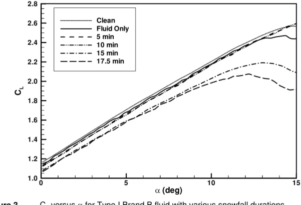
Clean Airfoil Aerodynamics
During the experimental campaign, the curve of lift coefficient, CL, versus D for the clean airfoil was measured at regular intervals to check for any inconsistencies in the base-line experiment. The curve labeled “Clean” in Figures 3 and 4 is the average of a number of dynamic “takeoff phase” experiments. The angle of attack at stall for the clean airfoil, Dsc, was found to be 15 deg. For D > Dsc the CL versus D curve exhibited significant variation, indicating the random nature of the progression of the stall. For this reason, the curves of Figures 3 and 4 have been terminated at Dsc = 15 deg. 0 5 10 15 D (deg) 1.0 1.2 1.4 1.6 1.8 2.0 2.2 2.4 2.6 2.8 CL Clean Fluid Only 5 min 10 min 15 min 17.5 min
Figure 3 CL versus D for Type I Brand B fluid with various snowfall durations
Since the end plates were of limited size, the airfoil experienced a significant level of induced drag, CDi. At the maximum lift coefficient, CLmax, CDi was estimated to be three times the two-dimensional profile drag, CDp. Consequently, the total drag coefficient measured by the balance, CD = CDp + CDi, was dominated by CDi. Subsequent changes in CDp, resulting from the presence
7
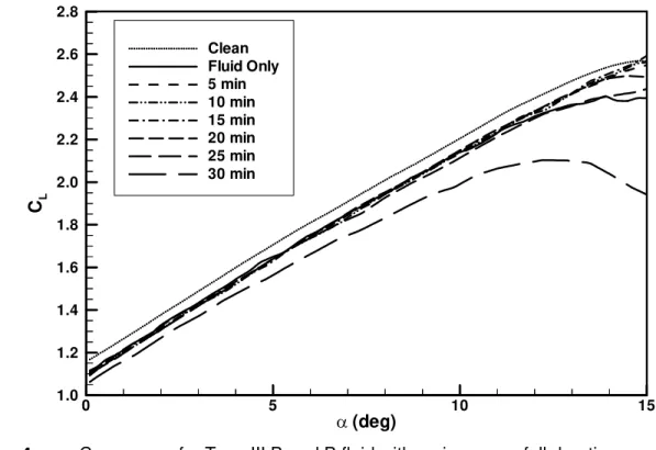
of contamination on the airfoil, were only a small fraction of CDi. The drag data were therefore found to be of limited use in the interpretation of the results and have not been presented here. Induced effects, due to the limited size of the end plates, also reduced the lift curve slope, CLD, as compared to that taken from the graphical data presented in Ref. 13. It is believed that this lower value of CLD does not affect the main conclusions, considering the comparative nature of the experiments. 0 5 10 15 D (deg) 1.0 1.2 1.4 1.6 1.8 2.0 2.2 2.4 2.6 2.8 CL Clean Fluid Only 5 min 10 min 15 min 20 min 25 min 30 min
Figure 4 CL versus D for Type III Brand B fluid with various snowfall durations
Aerodynamic Effects of Freezing Precipitation on De/Anti-icing Fluids
The experiments reported here are for two brands of Type I (de-icing) fluid and one brand each of Type II and Type III (anti-icing) fluid. The fluids from two different manufacturers have been labeled Brand A and B, respectively. For the Brand B Type I and Type III fluids, aerodynamic lift performance has been discussed in detail, since their performance was typical of the others tested.
Results for the Type I Brand B fluid are shown in Figure 3. A comparison of the CLmax for the “Fluid Only” case with that of the clean airfoil gives an indication of the aerodynamic impact of the fluid alone, being 2.4% at CLmax. This reduction in CLmax is attributed to the surface roughness created by waves in the residual fluid on the airfoil during the takeoff phase (Refs. 3, 4, 6 and 19). The CL versus D curves measured following 5 and 10 min of snowfall contamination were similar to that for the “Fluid Only” case, that is, they were slightly lower than for the clean airfoil for all D. During these two contamination phases, snow crystals falling into
8
the de-icing fluid were observed to melt shortly after impact. On the other hand, the CL versus D curves measured following 5 and 10 min of snowfall contamination reached a CLmax greater than that of the “Fluid Only” case. This is believed to be the result of the thinning of the fluid by the melting snow, thereby improving the clearing of the diluted fluid from the airfoil during the simulated takeoff.
Following a contamination phase of 15 min of snowfall, the fluid thinned sufficiently near the leading and trailing edges of the airfoil so that slush had begun to form in these regions. This slush was not removed by the aerodynamic shear during the simulated takeoff and as a result, the roughness present on the airfoil produced a greater loss in CL for all D (curve labeled “15 min” in Figure 3). At a snowfall duration of 17.5 min during the next test, the absorption capabilities of the fluid were exhausted and slush had accumulated rapidly on the airfoil. For this level of contamination, CLmax was reduced by 20.6% and Ds, the angle of attack at the stall for the contaminated airfoil, was reduced by 3 deg compared to Dsc.
Figure 4 presents the results for the Type III Brand B fluid. The CLmax for the “Fluid Only” case was 7.4% less than that for the clean airfoil. The CL versus D curves measured following 5, 10, 15 and 20 min of snowfall contamination were again similar to that with no contamination. For each of their respective contamination phases, snow crystals falling into the anti-icing fluid were observed to melt shortly after impact. The CL versus D curves measured following 5 to 20 min of snowfall contamination reached a CLmax greater than that of the “Fluid Only” case. This is again attributed to the thinning of the fluid by the melting snow.
The first small patches of slush were observed (again at the leading and trailing edges) following a contamination phase of 25 min of snowfall. As a result of these patches of roughness, a greater loss in CLmax was measured; however, this low level of surface roughness only produced a loss equal to that caused by the uncontaminated fluid (curves labeled “Fluid Only” and “25 min” in Figure 4). At a snowfall duration of 30 min during the next test, slush had accumulated rapidly on the airfoil. In this condition, compared to the clean airfoil case, there was a loss of CL for all D, CLmax was reduced by 19% and Ds was reduced by 2.5 deg.
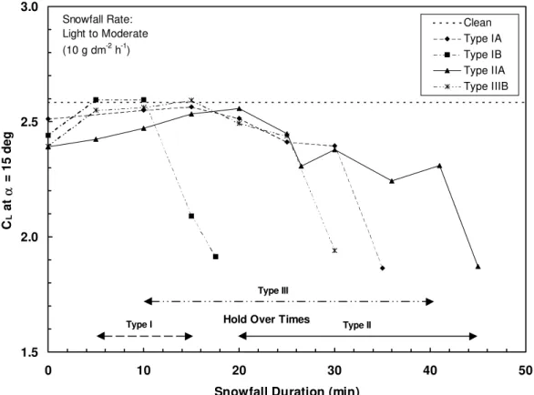
Results for other combinations of fluid Type and Brand (1A, 1B, IIA and IIIB) are summarized in Figure 5. Values of CL at D = 15 deg from curves similar to those of Figures 3 and 4 have been plotted as a function of snowfall duration. Fluids IB, IIA and IIIB all showed greater lift loss when uncontaminated (snowfall duration of 0 min) than did fluid IA. On the other hand, the Type IB fluid showed substantial lift loss considerably sooner than the other fluids. The holdover times appropriate to these fluid types are also plotted on the graph for comparison.
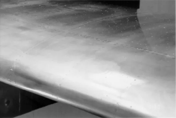
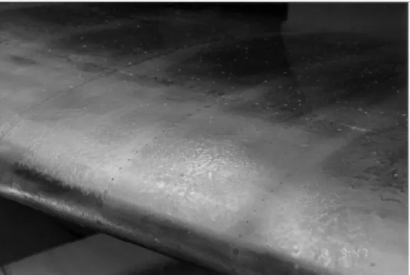
Examples of the rapid change of visual appearance for the Type I Brand B and the Type III Brand B contaminated fluids are presented in the photographs of Figures 6 and 7. In each Figure, the lower photograph is associated with the CL versus D curve that exhibited the greatest lift loss in Figures 3 and 4, respectively.
9 1.5 2.0 2.5 3.0 0 10 20 30 40 50
Snowfall Duration (min)
CL at α = 15 deg Clean Type IA Type IB Type IIA Type IIIB Type I Type II Type III
Hold Over Times
Snowfall Rate: Light to Moderate (10 g dm-2 h-1)
10
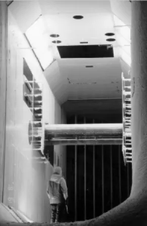
Figure 6a Type I Brand B (de-icing) fluid with 10 minutes of snow contamination
11
Figure 7a Type III Brand B (anti-icing) fluid with 25 minutes of snow contamination
12
Conclusions
Wind tunnel experiments have been carried out to investigate the aerodynamic performance of an airfoil and flap protected by de/anti-icing fluids while exposed to various controlled accumulations of freezing precipitation. The experiments have shown that the lift loss associated with the snowfall contamination of de- and anti-icing fluids accelerates rapidly once the fluids can no longer absorb the snow crystals falling onto them. This accelerated lift loss coincides with the visual failure of the fluid, that is, with the formation of a layer of snow on the fluid. The fluid failure was observed first near the leading and trailing edges of the wing section. The contamination period required to reach the visual and aerodynamic failure of the fluid was generally consistent with the corresponding values from the holdover time tables.
13
References
1. Ellis, N., Lim, E., Teeling, P. and Zhu, S., “Wind Tunnel Tests of Aerodynamic Effects of Type I & II Ground De/Anti-Icing Fluids on Small Transport and General Aviation Aircraft During Takeoff”, AIAA Paper 91-0763, January 1991.
2. Munafo, C.F. and Masters, C.O., “Evaluation of the Aerodynamic Effects of Commuter Class (Type 1½) Anti-icing Fluids on Small General Aviation Airplanes”, AIAA Paper 92-0643.
3. Carbonaro, M. and Cunha, F., “Aerodynamic Effects of De/Anti-icing Fluids and Criteria for Their Aerodynamic Acceptance”, SAE Aircraft Ground Deicing Conference Transcription of Presentations, Salt Lake City, Utah, June 1993.
4. Zierten, T. and Hill, E., “Wind Tunnel Investigation of the Aerodynamic Effects of Aircraft Ground Deicing/Anti-Icing Fluids and Criteria for Aerodynamic Acceptance”, Paper No. 19, AGARD Fluid Dynamics Panel Specialists Meeting on “Effects of Adverse Weather on Aerodynamics”, Toulouse, France, 29 April – 1 May 1991.
5. Van Hengst, J., “Flight Tests of the Aerodynamic Effects of Type I and Type II Ground De/ Anti-icing Fluids on the Fokker 50 and Fokker 100 Aircraft”, AIAA Paper 91-0785, January 1991.
6. Oleskiw, M., Penna, P., Crabbe, R. and Beyers, M., “Full-Scale Wind Tunnel Simulation of Takeoff Performance Degradation with Contaminated Fluid Runback”, American Helicopter Society/SAE International Icing Symposium ’95, Montreal, Quebec, Canada, September 1995.
7. Oleskiw, M.M. and Penna, P.J., “Wind Tunnel Wing Section Performance with De/Anti-icng Fluids and Freezing Precipitation”, SAE Aircraft Ground Deicing Conference & Exposition, Pittsburgh, PA, June 1997.
8. Moshansky, V.P., “Commission of Inquiry into the Air Ontario Crash at Dryden, Ontario (Canada), Final Report”, Minister of Supply and Services Canada, 1992.
9. Dubuisson, C., Bernardin, S., Laforte, J.-L. and Louchez, P., “Review of Aircraft Deicing and Anti-icing Commercial Fluids”, SAE Aircraft Ground Deicing Conference & Exposition, Pittsburgh, PA, June 1997.
10. Oleskiw, M.M., “Testing an Aircraft Wing Contaminant Sensor in Natural and Simulated Winter Precipitation”, NRC Institute for Engineering in the Canadian Environment Report IECE-CRT-CTR-001, January 1994.
14
11. Bachmeier, A.J. and Staff, “VTOL Propulsion Tunnel”, Reprint of article from NRC’s DME/NAE Quarterly Bulletin 1968 (1), April 1968.
12. Tyler, R.A. and Williamson, R.G., “Experience with the NRC 10 ft. x 20 ft. V/STOL Propulsion Tunnel – Some Practical Aspects of V/STOL Engine Model Testing”, Reprint of article from NRC’s DME/NAE Quarterly Bulletin 1973 (2), July 1973.
13. Wentz, W.H., Jr. and Seetharam, H.C., “Development of a Fowler Flap System for a High Performance General Aviation Airfoil”, NASA Contractor Report CR-2443, December 1974. 14. Galway, R.D., “A Comparison of Methods for Calibration and Use of Multi-Component Strain
Gauge Wind Tunnel Balances”, NRC National Aeronautical Establishment Aeronautical Report LR-600, March 1980, NRC No. 18227.
15. Inkpen, S., Brobeck, C. and Nolan, C., “Development of a Sensor for the Detection of Aircraft Wing Contaminants”, AIAA Paper 92-0300, January 1992.
16. Oleskiw, M.M., “Laboratory Evaluation of a Sensor for Detection of Aircraft Wing Contaminants”, AIAA Paper 92-0301, January 1992.
17. Society of Automotive Engineers, Inc., Standards Development and Research Division, G-12 Fluid Subcommittee, Working Group on Laboratory Methods to Derive Holdover Time Guidelines, Minutes of Meeting for November 20 and 21, 1997.
18. Brumby, R.E., “The Effect of Wing Ice Contamination on Essential Flight Characteristics”, AGARD Conference Proceedings CP-496, 68th AGARD Fluid Dynamics Panel Specialists Meeting on Effects of Adverse Weather on Aerodynamics, Toulouse, France, April 1991. 19. Crabbe, R., “Predicted Influence of Surface Roughness Including Fluid-runback Waves on
Airfoil Lift and Drag”, NRC Institute for Aerospace Research Laboratory Technical Report LTR-A-002, November 1995.
![Figure 1 End-view of airfoil and flap (dimensions in millimetres [inches])](https://thumb-eu.123doks.com/thumbv2/123doknet/14205835.480913/17.918.118.798.650.981/figure-end-view-airfoil-flap-dimensions-millimetres-inches.webp)