Digital / Analog Video An investigation into the theory, practice, and potential uses of digital and analog video combined.
by Tyler Peppel Submitted to the Department of Architecture in partial fulfillment of the requirements for the degree of Master of Science in Visual Studies at the Massachusetts Institute of Technology February 1984 The author hereby grants to MIT permission to reproduce and to distribute copies of this thesis document in whole or in part. CTyler Peppel, 1984
Signature of Author IV Tyler Peppel
January 20, 1984 Visibl-e }ang e Workshop
Dep9rtrkg 4/jo chitecture
Certified by f4riel ~
Associate Professor of Visual Studies Thesis Supervisor
---
---Accepted by Nicholas Negroponte
Professor of Computer Graphics Chairman, Departmental Committee on Graduate Studies
MIlibraries
Document Services
Room 14-0551 77 Massachusetts Avenue Cambridge, MA 02139 Ph: 617.253.2800 Email: docs@mit.edu http://Ilibraries.mit.edu/docsDISCLAIM ER
Page has been ommitted due to a pagination error
by the author.
Digital/Analog Video
An investigation into the theory, practice, and potential uses of digital and analog video combined. by Tyler Peppel
Submitted to the Department of Architecture in January, 1984, in partial fulfillment of the requirements for
the degree of Master of Science in Visual Studies Abstract
Video-resolution computer imaging combined with live action video offers a new range of possibilities to the visual communicator. Until now, computer graphics has been used with live action video only as a supporting element, indicative of the separation between the fields of computer graphics and video production.
This thesis bridges that separation by combining digital and analog video into a single visually coherent image. Video-resolution computer graphics are integrated technically and visually with live action to create a hybrid of the two: Digital/Analog video.
To accomplish this integration, software was written to manipulate digital video images and create highly
articulated key mattes, as well as to control analog video equipment. These tools were used to
produce videotapes that served as an investigation into their technical and expressive possibilities and the new potential they suggest for visual communication.
Thesis Supervisor: Muriel Cooper
Table of Contents Page 2 0.2 Abstract 4 0.3 Preface 7 0.4 Acknowledgements 8 1.0 Introduction -project description
-what was undertaken and why
11 1.1 Existing analog and digital video imaging tools
20 1.2 How these tools are integrated: an approach to technical considerations specific to that
integration
22 1.3 A digital/analog video production studio: How the integrated tools function together as a
production environment.
34 1.4 A Software Package for Digital / Analog Video 47 1.5 Production Processes: How three digital/analog
videotapes were made
71 1.6 Conclusion: results of the work, suggestions for further research
76 2.0 Introduction to Part Two
78 2.2 Design for digital / analog video
97 2.3 A Studio of the Future and what might happen there
105 2.4 Further Extensions 110 2.5 Conclusion to Part Two
113 3.2 Bibliography
0.3 Preface
"Two old Chinese sages have ceased all activity and proselytism, and speak as little as necessary between themselves. They go down to the river bank every morning to catch a fish for their dinner. Sitting one morning alongside one another, silently holding their lines, one feels a tug on his and begins to gently pull in his line, evidently a large catch, with the other watching.
Presently a beautiful girl's head appears above the water, expressing fright, but she is hooked and cannot get away. The fisherman motions reassuringly to her to come nearer, bends down and lifts her out of the water. A long tail covered with fish scales terminates the body. Taking the mermaid on his lap, the sage gently disengages the hook while she docilely holds on to him. Then he lifts her and places her back in the water. Meanwhile, the other sage has been quietly watching the operation; after a minute, he utters one word: "why?" To which his companion, after a minute's reflection, replies "how"?"1
How and why could be seen as two parts to a single question or as two completely unrelated forms of
investigation. In the context of this thesis, the "how" questions are about machines, the "why" questions about
visual ideas.
Machines and visual ideas could be titles for the two main sections of my writing: Part One describes how things were done, and the technical problems,
tools, and solutions: a hopefully objective account of the specific facts of a research process.
Part Two describes why Part One might be important.
It touches on more subjective matters and how they come to bear on a process that requires technical and aesthetic issues to converge in a way that makes them inseparable elements of a single endeavor. How smoothly they converge
is only one aspect of our complex relationship
with machines. Part Two is about that relationship. In doing this work, I had several roles: Technician, (How does it work? How could it be made to work better?) Designer, (What will it look like? How will others see it?) Artist, (What can be expressed or proposed with it?),
and Seer, (What will it be in the future?). The subject is new, and consequently lacks a specific history. General
histories on visual communication have already been written, so I tried to keep the writing current. References to
video/graphic design are quite rare, worthwhile ones are rarer still. It is a sad commentary that so little
literature exists on the visual design of our most
powerful medium of communication. As television becomes more of an information source and less of an entertainer,
the promise of an ever more wide-ranging and articulate video image. With informed producers, artists, and
0.4 Thank You Mark Abbate Kate Adams Olga Antonova John Barnett Muriel Cooper Glorianna Davenport Robert Gray Sarah Griffith Rob Haimes Steve Kuettel Ron MacNeil Anne O'Toole Kathy Peretta Patrick Purcell Katrina Resevic Mike Roper Anne Russell Niti Salloway Russell Sasnett Dorothy Shamonsky Lee Silverman Paul Souza Brian Swift Alexandra Tana John Thompson Lincoln Yaco
1.0 Introduction
Every media technology has been touched by the computer, and we are now seeing only the the first results of the use of computers as tools of visual communication.
Design, production, and distribution of media
communication in radio, television, and publishing has been transformed by computer technology and will
change even more in the future. Not only have
computers served the needs of existing media, they are rapidly becoming a communications medium in their own right.
The pervasiveness and potential compatibility of digital information has begun to blur distinctions between media that once needed their own individual and incompatible technologies.
Digital sound, digital pictures and digital pages are all becoming a unified information source, all processed and transmitted by computer technology. Only at the final step of the process do they regain an analog identity as sound, picture, and page. Until then they are digital information which is controlled and processed by other digital
information. This has wide-ranging implications for all aspects of media production, distribution, and reception.
This thesis is concerned specifically with
the integration of computers and a single medium: NTSC video. Its technological base is a computer graphics system at the Visible Language Workshop at MIT which has primarily been used as a generator
and processor of still images for a variety of graphic output purposes. The theoretical base of the thesis is the belief that computers and video together offer a new range of possibilities for communication and
expression for the visual communicator.
To achieve this integration, existing equipment was modified, interfaced, and configured into a
prototype studio configuration described in section 1.3. The technical focus of the thesis was on two direct
applications of computers to video production: imaging and device control. Other potential
applications are discussed in section 2.4. Digital video production software was written as a component of the prototype studio; this software is described
in section 1.4. Videotapes were produced in the studio and were submitted as part of this thesis.
Production of these tapes is described in section 1.5.
Coupled with technical problem solving was an
investigation into the implications of this work for makers of visual communication. Issues of design
issues are described in section 2.2, along with an interview with a broadcast designer who uses computers for video production.
Speculation on a possible digital/analog production studio of the future occurs in section 2.3, and a potential relationship between other media and digital/analog video production is described in section 2.4.
If the recent past of digital/analog video production is low-resolution computer graphics overlaid on analog video, and the present (as
represented by this thesis) is a fuller integration of the two into a single visually coherent image, then the future of these tools might be the potential relationship between intelligent machines (which are
capable of recognizing, creating, and integrating images) and analog video images and events. If realized, this potential could offer us greatly more powerful tools to share ideas and information, as computers take on more of
the labor of production and people are freed to refine and share their ideas.
1.1 Existing Analog and Digital Video Imaging Tools
---The most direct way to approach these tools is to clarify by examples the distinctions between analog and digital.
There are several analog and digital devices which by now are familiar to almost everyone. A simple mercury thermometer and an ordinary slide rule are good examples of analog devices; in the thermometer, the height of the mercury as measured on an appropriate scale is proportional - or analogous - to the
temperature of the surroundings; the slide rule is a kind of analog computer in that the distances between the scribed lines are made proportional to the logarithms of numbers so that by adding distances one can in effect multiply numbers.
The ubiquitous electronic pocket calculator and of course the digital clock are obvious examples of digital devices. Comparing the slide rule and the pocket calculator, we can illustrate two of the essential differences bewteen analog and digital systems. Analog devices operate with continuous data, which means that over their operating range, any
desired number can be set it or read out. Digital devices, on the other hand, deal with discreet or stepped data: whatever the least significant digit is, it can only change by one whole unit. And this distinction relates directly to the second essential difference - that of resolution. Resolution, in the sense used here, provides
a measure of the smallest possible increment of change in the variable output of a device. The resolution of any analog device depends on the exactness of the analogy that is used, on a factor which relates the magnitude of a
number to the precision of its representation by the device.
Analog Television
Conventional television is analog television. When a scene is scanned, the current from the cathode of a television camera tube increases with the amount of light - from each spot in the scene - falling on it. This variable current is used to obtain a signal which is processed in the studio to obtain a broadcast signal. The signal that is then radiated from the broadcasting antenna passes through the atmosphere to a recieving antenna where it is sensed as a weak "field strength".
In the reciever the process is reversed: and increased positive signal voltage applied to the control grid of the picture tube causes an increase in luminance at a given point on the screen. Thus, in a television camera, an electronic signal is used as an "analogy" to represent a pattern of light, while in the reciever, a pattern of light is generated as an "analogy" to represent an
electronic signal. For color transmissions, red, green, and blue spot brightnesses are converted to currents in
the camera and back to tiny colored light spots in the reciever. The eye of the viewer blends the three colors of the spots additively to produce a full color picture, and since the pictures are sent in "frames", persistence of vision permits the viewer to percieve smooth and
continuous motion - just as with motion pictures.
Digital Television
In digital television systems, the voltage waveform that is generated by the camera to represent the
brightness of a picture element is measured or "sampled" millions of times each second. Each sample is then
"quantized": it is assigned the number of the nearest step that the system can resolve. Two kinds of quantizing error must be considered here because (1) a sample that
is exactly between two steps can be quantized either way and (2) all digits beyond the resolvable limit will be
dropped. In electronics, such "quantizers" are called analog-to-digital (A/D) converters. Many of them have
enough digits - you could say "places" or "significant figures" - to be able to resolve one part in 256 or better. Experimental quantizers have been built that can reolve at least one part in 1024.
On the face of it, sampling and quantizing would
seem to work to our disadvantage. After all, instead of taking the whole voltage waveform as is done in
Futhermore, there must inevitably be a quantizing or rounding off error each time we substitute the nearest quantizing unit step for an actual measured value. Nevertheless, if we take our samples accurately and frequently, and then quantize in small steps to
minimize rounding-off errors, we can use the collected and quantized samples to recover a waveform
indistinguishable from the original.
Still, why is it better to have this collection of discreet samples than the whole continuous waveform? The answer is that quantized samples can be encoded to make up a new signal that in principal can be processed, recorded, transmitted and ultimately converted back into an analog signal for playback -all with much less likelihood.of errors than the
original signal could ever be. Instead of manipulating the waveform itself - or some characteristic of it, we can manipulate information about the waveform, and this information can be used eventually to reconstruct the desired waveform.
The problem with digital broadcast television, at present, can be summed up with one word: bandwidth.
Bandwidth is the differnece between the upper and lower limits of the frequency band. Because an ordinary
color television signal has a bandwidth of about 4.5 MHz and every individual cycle can be important, we
must sample approximately 11 million times each second. Using an eight-bit binary number to describe each sample, It is obvious that we would need to be able to process about 88 million bits per second. Consider that
transmitting this quantity of information is
equivalent to sending both the Old and New Testaments of the Bible more than ten times in the course of a second.
This extrordinary bandwidth problem is the primary reason that no one at the present is even considering broadcasting this data stream, but only using it between analog camera and the analog transmitter. Still, intense efforts are being made to circumvent - to any degree possible and by any means possible - the requirements
for such large bandwidth. The biggest motivating factor to develop digital television at the moment is to get digitized signal processing equipment into studios. With such equipment, special effects, image enhancement
and many other functions could be handled with great ease; 2
it is likely that many could even be automated.
Until the raster-scan display became a feasible way to observe graphic output from a computer, the relationships between computer graphics and video were rarely explored. With the advent of raster scan displays the relationships became obvious: computer output could now be observed on a cathode ray tube very much like a standard home television
receiver. Hardware became available which could encode the RGB video signal from the computer into a standard NTSC
compatible video signal, and then back to RGB if necessary. The concurrent dramatic increase in the imaging
power of computers (although at high cost and low access) made computer-generated NTSC video images a reality. Systems
were developed to bring together computer generated and
analog video, some of which will be discussed here. The high cost of hardware and software used in these systems has
inhibited their development and kept the market for them small and specific. Lower costs will broaden the range of applications and present new design possibilites for visual
communication, design, and fine art.
Systems now on the market are usually a configuration of: -a microcomputer with soft and hard disk drives (10mgb) for
image and font storage.
-a frame buffer (usually 512 x 1024)
-a servo controller for computer control of videotape recorders
-a fixed video camera for digitizing -a tablet and light pen
-a stardard ascii keyboard
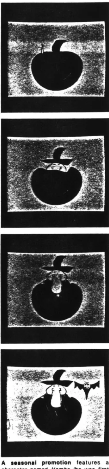
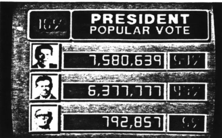
One existing system is the Dubner CBG-2, sold by Dubner Computer Systems of Fort Lee, New Jersey. The system sells for around $100,000 and is designed for use by broadcast networks and large local television stations.
The CBG-2 was developed in collaboration with the news department of ABC television and three Dubner systems are presently in use by ABC to generate news and weather
graphics, logos, and network promotional spots. The system operator has the option of digitizing a
backround from existing artwork and photographs or starting with a standard backround format which has been stored in memory.
Digitized fonts of type can be called when text is needed and limited animation can be performed by
manipulating color matrices to simulate motion. Programs are available to draw 3-d curves and to shrink and expand images. Individual video frames can be grabbbed, written into the frame buffer and manipulated, then written back out onto videotape. The system is also capable of the usual
visual effects associated with video switchers such as wipes, keying, fades, and dissolves. The following article
from Broadcast Engineering magazine describes the use of a Dubner System at ABC Television in New York.
Two other very similar systems are the ADO system by Ampex Corporation and the IMAGES system which is marketed by
Computer Graphics Laboratory, a corporation formed by the New York Institute of Technology to market its computer graphics systems and software. Both the ADO and IMAGES systems are more oriented to user creativity than the Dubner system, and stress the fact that the user can
paint and draw original pictures, rather than relying on preexisting backrounds and and digitized fonts. There seems to be a trade-off between the creative flexibility of the system and its usefulness; most of the effort that goes into designing a system seems to be directed toward user friendliness, but sometimes this happens at the expense of the creative possibilities. The individual system components are usually off-the-shelf hardware; the problem is to configure that hardware into a
responsive and user-friendly package.
User friendliness is heavily stressed selling point for all of the commercial systems I found information on;
product descriptions boast that the user needs absoulutely no knowledge of computers to operate the system.
By protecting the user from making "mistakes" the system often limits its own power: if users do know computers and programming, on these systems they have no option to put that knowledge to use. A more serious flaw of the commercially-available systems is their inevitable
"black box" nature. It is expected that some aspects
of a system would be proprietary, on the other hand, many systems allow little user input beyond the selection of canned effects programs. Instead of providing the user with the tools to build their own visual vocabulary, most
systems systems limit user input to the operation of a crude paint program and a few stock effects. A
its paint program is flexible and powerful, but its motion capabilities are limited.
Prototype systems are under development in non-commercial environments such as the Jet Propulsion Laborotory in
California, and Cornell University in New York. Without the pressures of the marketplace, application range broadly from simulation and design visualization (with computer models in analog environments), to non-destructive testing and the creation of fine art. The next section describes a protoype studio system put toether at MIT to explore
capabilties and applications not currently addressed by commercial video graphics systems.
1.2 Integrating the Tools
---Digital and Analog video devices are often designed without regard to their compatibility. Early frame
buffers generated a video signal meant only to be displayed on RGB video monitors. The frame buffer used in this
project, a Grinnnel GMR 270, (circa 1978) was not video compatible in either its timing frequency or video line rate with RS-170 video specifications. Extensive
modifications were performed by Film/Video section
technician Mark Abbate on the frame buffer sync-interface card to make the video subcarrier rate externally variable and to reset the horizontal and vertical drives from an external sync generator. This modification proved to be
time-consuming and expensive, but was necessary if the video output was to be processed and recorded with standard NTSC equipment.
(Grinnell, along with almost all other frame buffer manufacturers, has since started to manufacture their
equipment with an NTSC RS-170 video output as standard equipment.)
A Lenco 850 NTSC Encoder was used to encode the RGB video to NTSC. Its crystal oscillator was removed so it could be slaved to an external subcarrier frequency at the same rate as the video coming from the frame buffer.
An Electrohome NTSC Decoder was purchased and installed to decode NTSC signals coming from videotape into separate Red, Green, and Blue channels for digitizing. Switching was provided to send these signals independently to
the video input of the frame buffer.
A single board computer was purchased and installed as an interface between the Visible Language Workshop's Perkin-Elmer 3220 and the Film/Video Section's Ampex VPR-2B 1" videotape decks. This interface was built
by VLW research associate John Thompson, and although its initial purpose was to allow single-frame recording for computer animation, it is also essential for software
scripting of video device activity.
Kate Adams did programming for a software package as her undergraduate thesis (described in section 1.4) to allow graphic manipulations to be performed on moving and still images for digital video production.
1.3 A Prototype Digital / Analog Video Production Studio
---
---A prototype production studio was put together through the cooperation of the Visible Language Workshop,
Film/Video Section, and Educational Video Resources, all of MIT.
The purpose of the studio was to mix and process a variety of analog and digital video sources, and to have some of that mixing and processing under computer control.
Because equipment was borrowed from various departments, the studio had to be temporary. At the time of this
writing, many of the video and computer resources at MIT remain isolated; part of the aim of this prototype
studio was to bring these resources together to explore the technical feasibility and creative potential of an integrated production environment.
The system diagram shows a basic configuration. Several different configurations were tried to test a range of possibilties.
The basic functions of the studio were to: -mix analog and digital video by keying
-digitize imagery from a live camera input or frames from a pre-recorded videotape input
-use those digitized frames as "templates" for the construction of digital graphics and highly articulated digital video mattes
Analog Video
User Station
System Diagram:
Digital/Analog Video Production Studio
-- +1 in
out
I In & Out
-design and produce computer animation that could be fully integrated with analog video
-orchestrate various input sources and record program outputs through computer device control of video tape recorders
-develop and utilize video production software tools in the production process
-begin to develop and test the concept of "scripting" events in computer memory as a means of producing videotape
These capabilties can be utilized individually or combined, and the ease and efficiency with which they can be used determined the success of a particular configuration.
The studio was intended to be used by one person
in most applications. If a live camera input was needed, additional people would operate a cameras and any other remote equipment. Because of spatial limitations,
the video tape recorders were separated from the
computer workstation by a distance of about 100 feet. Ideally, the decks and graphics station would occupy the same space.
Along with the equipment normally found in a video production studio the user interacts with a computer terminal, program menu monitor, and graphics tablet. Frame-buffer output is displayed as NTSC encoded
video on an NTSC monitor. The terminal allows the user to input and run programs which either generate images in the frame buffer and/or control production equipment. Programs in this application can become essentially
Computer Graphics Design Station
in the frame buffer and/or control production equipment. Programs in this application can become essentially
scripts which are lists of commands to carry out
operations like pausing a video tape recorder, loading a stored image into the frame buffer, generating an image digitally, or digitizing a specified frame on a
pre-recorded videotape. Effects programs can be run from the menu monitor (for a visual preview) or specified from inside a script program, once the event time and duration of the effect have been established. A simple
script program outline might look like this, with one deck, (deck A) holding pre-recorded source material, and the
other (Deck B) recording the mixed output: DK A = Source Deck
DK B = Record Deck
SMPTE Code Command
---A 00:20:00:00 Digitize frame No. 00:31:44:22 B 00:30:00:00 from source deck "A", and hold it in the frame buffer. Zoom in to the upper right quarter
of the image
A 00:20:30:00 Roll deck A forward in
B 00:30:00:00 record to frame 00:20:30:00
A 00:20:15:00 Rewind deck A to frame 00:20:15:00 B 00:30:00:00
A 00:20:15:00 Clear the frame buffer B 00:30:00:00
A 00:20:15:00 Load a graphic overlay from disk B 00:30:00:00 storage into the frame buffer
0
A 00:20:15:00 Cue the operator to set a key B 00:30:00:00 level for the graphic overlay and
signal when finished.
A 00:20:30:00 Roll both decks A+B forward from B 00:30:15:00 their present postitons for
15 seconds with A in play mode and B in record mode. After 5 seconds, pan the overlay graphic to the left and off the screen.*
A 00:20:30:00 Rewind deck B to 00:20:00:00
B 00:20:00:00 and ask the operator for a command.
* Digital pan start and stop times and start and stop
positions are specified ahead of time by the operator during a rehearsal of the effect.
Computer animation can be designed and produced in the prototype studio using a mixture of device control and image
generation. The configuration shown in illustration 1.3.1 also allows for the design of animation around analog video, by digitizing keyframes of the analog sequence at
predetermined intervals. The frequency of the keyframe interval is set by the user according to the degree of precision needed in integrating the sequence of animation with the live action, with a higher frequency giving
greater precision. These digitized keyframes can then be used as templates for the placement of animated objects and the specification of their paths through 3-dimensional space. Colors can be matched or contrasted with the digitizing keyframe, since the frame
Using a sequence of frames, positions on a motion path can be checked by keying keyframes of the animation over
corresponding keyframes of the live action sequence. An animation software package exists at the Visible
Language Workshop which allows the user to specify a variety of shaded geometric objects and also 3-d shapes that can be "turned" on an interactive graphic "lathe".
The package was written by Karl Sims and upgraded by
John Thompson. Once specified, objects can be moved through three-space in assigned increments, or frames. After all parameters are specified, sequential frames are drawn, left in the frame buffer for a specified time, then erased. The process is then repeated for each succesive
frame. This process of drawing, erasing, and re-drawing happens automatically once everything is specified; unless the process is interrupted all frames of a sequence are drawn in the order they will be viewed.
A device controller was built by John Thompson to control an Ampex VPR-2 1" videotape deck. This deck is controllable by TTL logic via an RS-232 port normally intended for communication with a microprocessor-based edit controller for videotape editing. In the animation design station, this port is used to contol the videotape deck with the same software package that is used to draw the individual frames of animation. The main clock of the system is the SMPTE time code shown in the sample script
above. If command strings are embedded in the frame-drawing software, the tape deck can be told to record a specified number of video frames of each complete drawing. In this way, animation can be recorded automatically once all criteria are set. For our uses, an average of two video frames are recorded for each animation drawing, which means that 15 drawings are displayed for each second of running time. This is comparable with film animation where the frame rate is 24 frames per second; two frames
photographed of each drawing and 12 drawings are viewed in each second of running time. At the animation design station, a single drawing can be recorded for any
number of video frames, and this rate can be varied within an animation sequence.
The automated single-frame recording capabilties at work in the animation design station can also be applied to the manipulation of live action video. Live-action frames can be decoded to separate R, G, and B channels and digitized in sequence, manipulated in the frame buffer, NTSC encoded, and sent back out to videotape. The manipulation can take many
forms: adding or deleting portions of an image, overlaying
text, color correction, varying the resolution, adding animated objects, or all of the above. This is a very process-intensive method of production given the limited resources of the
prototype studio. It is also time-intensive; ideally one would want to speed up the operation by fully
automating as much of the manipulation process as possible. A dedicated system that was immune from the delays associated with time sharing would also be desirable. Even minimal
processing on each frame becomes intensive when 30 frames are required for each second of video output. An alternate method might be to roll the videotape on both source and record decks continuously but more slowly the normal tape
speed. How much slower would depend the the processing abilties of the equipment at hand, but it is not hard to imagine that
this method could allow for speeds close to half the normal tape speed, or one-half hour of processing time for fifteen minutes of material. Equipment now exists which can digitally record and display in sequence eight minutes of full
resolution video at normal play speed. With expected future increases in memory capacity, single-frame processing of this type will be much less time and equipment intensive, and thus useful in a much wider range of applications.
Event Scripting
Event scripting, or the organization of video device events in a software list structure, is a central concept of both the prototype studio and the production studio of the future described in section 2.3.
Current video editing systems commonly feature digital
edit memories that allow rehearsal and refinement of a series of video edits. Some digital effects systems allow a series
effects commands to be stored in memory and executed in sequence.
For scripting purposes, events may be defined as almost any change in the status of a device during the production process. Events could be any activity of: videotape
recorders, computers, frame buffers, switchers, slide
projectors, film chains, character generators, and possibly also cameras.
A central script program would be executed by a computer which is interfaced to the devices listed above. The script itself is essentially a list of commands to the various devices, with the built-in ability to "listen" either to an internal clock or the SMPTE time code numbers coming
from one of the videotape recorders. Part of what makes the event scripting concept powerful is the fact that it can applied to any production situation from a microcomputer and
1/2" video deck to a very complex broadcast production studio. Easily accessed and editable command lists control video and computer devices and and execute the commands at pre-specified times.
Event scripting gives the user two distinct advantages, one being the unlimited repeatability of sequences so that refinements can be made, and the other, which is probably more important, is that the script completely divorces the ergonomic limitations of the user from the processing
the piano, where the player is limited to pressing a maximum of ten keys within a limited distance to each other and with a limited amount of speed. A script would allow the piano player to press any number of keys at any
time. Just as this would extend the musical capabilities of the piano, event scripting would extend the visual
capabilities of video. Event scripts for productions with very similar and repeated formats (news broadcasts, for example) could be prepared in advance and used repeatedly, especially if video segments were held on-line in digital memory locations into which they are pre-loaded at the
start of the production.
A Script Structure
Because all scripts are written to control device-related events, they can share certain characteristics. One level of script activity would be a "listener" which monitors the status of all devices addressed by the script and compares the status to the status requirement of the next event on the event list. When device status matches the listed
event, the event is begun. That event is immediately moved from the top of the list and the next event moves to the top to replace it. Device status information would relate to the functions of that device, (such as paused, stopped,
recording,) or a SMPTE time code number.
The evolution of a script would begin with its generation through a mixture of keyboard commands and performance of
script events by the operator. When events are performed by the operator, the scripting software remembers the
operators actions so they can be played back in combination with keyboard commands. The sequence is frequently
rehearsed and refined by editing the event list. Event editing can mean adding or deleting events or changing
the timing commands. Timing might be addressed as either event times, which might be the starts or finishes of
events, or in blanket operations that might extend or compress a sequence by adding or subtracting a given amount of time evenly throughout the sequence. Scripting could also, if needed, take on tasks that are
peripheral to the production such as adjusting monitors to different brightness levels according to the time of day or keeping records of equipment use.
1.4 A Software Package for Digital / Analog Video
--
---A software package for digital / analog video production was designed, programmed and installed on the Visible Language Workshop computer
graphics system. Kate Adams wrote programs (as her undergraduate thesis in computer science) and
contributed immeasureably to the design of the package and in particular to the user interface. The programs listings are also on line in
>u>kma>video source.
The structure of the package was based on already existing tree-structured menus at the Visible
Language Workshop. These menus allow the user to access a variety of graphics manipulation software to design and layout pages, paint on and manipulate single images, and generate sequential animation drawings. The video menu was based on the same
structure as the other menus in order to be
consistent with an already existing and successful mode of user interaction that uses two display screens (one for image and one for menu) and a graphics tablet with a 4-button puck.
When the NTSC video output of the computer graphics system was modified to allow recording and processing
of the video signal, the menu was developed to allow use of the graphics system as a video production tool. Programs were developed to allow manipulation of the digital image in a controlled period of time. Some programs used analog video effects such as fades, wipes, and dissolves as their original basis, others were written specifically to facilitate production
of digital / analog video, and others were based on existing still graphics manipulation programs that were modified for video production.
The following is a list of each program on the menu. The program name as it appears on the menu monitor is followed by a description of what that program does.
What is
"What-is" displays an alternate menu with the same programs names as the original menu, except that they
have question marks added. If you choose a program with a question mark, a tutorial on what the program does and how to use it appears above the menu.
If you choose items without question marks, you actually run the program.
Most programs start whatever they do when
you tell them to, i.e., they don't start immediately after you specify the last parameter. This allows you some control if you want to sync the effect with another event.
Effects
Most these programs create real-time effects for videotape sequences. The types of effects fall into five categories - wipes, pans, zooms, fades, and dissolves.
Wipes cover or uncover the image on the screen with some solid color in a controlled way. A second video picture can be keyed into the
solid color during the wipe.
Pans start off zoomed in on a certain part of the screen, and then move (at a chosen speed) to another point, while zoomed in.
Dissolves fade one image out while another fades in.
Pictures
This provides access to several useful screen and image utilities that allow the user to load
stored images into the frame buffer, erase overlay planes, and view a picture directory of all images stored on disk.
Video
This menu level will allow you to send commands to the one-inch video deck.
You can tell it to find a specific frame, play a specified sequence on a pre-recorded tape, or start recording - either by giving commands from the menu
directly or from inside one of the effects programs.
Outside
All the options at this level will send you to other menus, such as sys (for painting, scaling, etc), key (the 3-d animation program), compose (for
text layout), and bigpic (the page organization system). In the process you will leave this menu, and possibly lose what's on the screen.
Wipes
Wipes cover or undercover the image "underneath" them, in some given pattern and time-interval.
The wipes available here are mostly solid-color wipes, with the idea that a second video image
could be keyed into the solid-color area, giving the effect of one image replacing the other.
White Wipe
This is an overlay plane wipe. You specify a "start" rectangle, an "end" rectangle, and a delay. (A delay of 0 is instantaneous, 300 is a nice smooth rapid
second, coloring or uncoloring the overlay plane, depending on whether you specify Trans-to-White or White-to-Trans. (You may want to think of tiny rectangles as points and long, thin rectangles as
lines.) Between successive wipes, you can clear the overlay planes. If you don't, the overlay turns red in between effects so you can see the white outline
rectangles, and the image underneath.
Window Wipe
You specify: a "start" rectangle (using the z button on puck), a "start" color (using sliders - z button changes
slider value, press #2 button when satisfied with the color patch shown on the lower right corner of the display).
Then you do the same for "end" rectangle and color. After hitting any button on the puck to start
the effect, the space between the start and end rectangles will be colored in - starting at the start color, and gradually fading to the end color.
Soft Edge Wipe
The edge of this wipe is a stippled pattern that looks like an airbrush. It is an overlay wipe, and can be specified in 6 overlay colors. White is opaque, but all the others are translucent.
At the expense of smoothness, you can make faster by giving it a larger number for speed. There are currently two versions of this wipe
-"horizontal" wipes from the bottom of the screen to the top, "vertical" wipes from the left to the right
Aperture Wipe
A white, gradient, (black to white) or black wipe that
closes in on the center of the screen like a camera shutter. The white version is an overlay wipe (does not effect
the picture underneath) and can also be run backwards -from a completely white screen, the shutter "opens" to reveal the picture.
In addition to selecting white, gradient, or black, you must enter a delay value that determines the speed
Corner Wipe
This wipe goes from the lower left corner to the upper right corner. The edge is connected to the other two corners,
so it is angled in the center.
You specify the delay (speed) of the wipe, and whether you want a black, white, or gradient edge. White wipes are overlay wipes.. .they won't effect the image underneath.
Center Wipe
This wipe starts at both the lower left corner and the upper right corner, and wipes in towards the center. It is like a corner wipe, only happening from two corners at once. You specify the delay (speed) of the wipe, and whether you want a black, white, or gradient edge.
White wipes are also overlay wipes.. .they won't effect the image underneath.
Random Wipe
Random fills the screen with rectangles drawn at random positions on the screen. You specify size and color of the rectangles and the speed at which they are drawn.
Pan
Pans start off zoomed in on a certain part of the screen, and then move (at a chosen speed) to another point, staying zoomed in. There are two common types of pans - horizontal pans and tilts
(rolls). A horizontal pan goes from one point on the horizontal axis to another point, without
changing the height. A tilt, on the other hand, scrolls along the vertical axis. Tilts can be used for rolling credits.
In addition, this menu layer also allows for "endless" or "wrapping" pans, and for pans that run during other transformations on the image.
Tilt
Tilt incrementally shifts the entire screen image vertically. You specify two points: the first point will be in the center of the screen when you start
the tilt and the second point will be in the center when the tilt finishes. You also need to specify the
speed of the tilt, and the zoom level, since you can only tilt when you are zoomed in:
zoom factor: 0 1 2 3
pixel size : lxl 2x2 4x4 8x8
Horizontal Pan
Horizontal Pan incrementally shifts the entire screen horizontally. You specify two points: the first point will be in the center of the screen when you start
the pan and the second point will be in the center when the pan finishes. You also need to specify the
speed of the pan, and the zoom level, since you can only pan when you are zoomed in:
zoom factor: 0 1 2 3 pixel size : lxl 2x2 4x4 8x8
Zoom
Zooms in on the image to the level you specify. The image remains zoomed in until you zoom out. This allows you to run other programs, such as wipes and fades while you are zoomed in. You can
shift the x-y position of the zoomed in image with the joystick.
zoom factor: 0 1 2 3 pixel size : lxl 2x2 4x4 8x8
Fade
Fade fades the entire screen or a specified part of it to a specified color. You specify the
number of steps in the fade; the more steps the longer it takes.
"Absolute" fades color values that are closer to the value you are fading to first, then the other values follow.
"Relative" fades each color in the starting
image according to its RGB value: values farther from the color you are fading to fade in faster,
and lower values follow in descending order.
Dissolve
A dissolve fades out one image while another image fades in. To do a dissolve between two pictures, you must first make a composite picture from them, using gen_comp. Then, run "dizzy" to do the dissolve. Another way to simulate a real-time dissolve is to generates large number of in-between "stills", and
then flip through them rapidly, like an animated flipbook. "Strip" and "Flipbook" do just that.
Gen_Comp
GenComp generates a composite image from two saved images that you specify at the terminal keyboard. The generating process looks like a picture load and takes about the same amount of time. After the composite is completely loaded, you can start the dissolve by choosing "dizzy".
Dizzy
Dizzy performs the dissolve on the composite image generated by "gencomp". You can choose a fast or
slow dissolve, and the number of times you want to repeat the dissolve.
Strip
Strip generates a series of miniature pictures that are displayed in sequence when you choose "flipbook". You specify the starting and ending pictures of the strip. If you specify one picture
to start and another to finish the strip will generate a continuous dissolve between the two images. If you
specify the same image to start and end, you will generate a strip of identical images. In either case you specify the number of images in the strip and their names from the terminal keyboard.
Flipbook
Flipbook displays the images generated in "strip" one at a time, full screen. You specify the speed at which they are displayed, the number of images
in the strip, and whether you want to see the
sequence repeat continuously from beginning to end, or from beginning to end and then backward to the beginning.
1.5 Production Processes for Digital/Analog Video
This section describes the production of three videotapes made during late 1983 and early 1984 at the Visible
Language Workshop, MIT. All of them mixed digital and
analog video, and all of them involve a computer simulation of an alternative reality. In some tapes the simulated
reality is a believable one, intended to serve as a model for a proposed change; in other cases it becomes an end in itself; its only connection to the real world is the
visual expression of an idea.
In each case the analog world as recorded by the video camera is combined and/or manipulated with comput.er graphics in the form of stored images, digitized type
fonts, program-generated images, digitally generated external key source mattes, or single frames digitized
from videotape. No analog manipulation was used other than luminance keying and videotape editing.
The fact that the hardware and software components used to produce the video were reconfigured many times presented opportunities for full exploration of the techniques
described. These opportunities would not have occurred in a more stable production environment, however a more stable environment would have fostered a fuller
of production. The expectation for the work was that it provide a vehicle for wide-ranging exploration of the production possibilities for digital/analog video with
the technical capabilities of the moment. Others will have their own expectations for their own work; this description is offered in the hope that the specifics of my experience might have a general application as well.
The first tape to take advantage of new capabilities was an attempt to simulate an interior space digitally.
An analog inhabitant was then keyed into the simulated space, in such a way that the person could see herself "in" the simulated space during the taping by looking at a nearby monitor. This would allow her to interact with the simulated space and control her movements accordingly. The interior spaces were simulated on the Visible Language Workshop computer graphics system using simple interactive graphics programs which fill and shade polygons which are generated by connecting a series of points input from a graphics tablet. Except for a few
pictures hanging on a simulated wall of one of the rooms, all the graphics are program-generated. (The wall pictures are reductions of analog images which have been digitized.)
Simple programs were used for image generation in order to speed interactivity and to see if believable spaces could be generated and quickly edited.
?1VVU1~tAt1~ 7 -:---r--~~--*
~wis~&f ~
~(V~A4
\/y
\,
r~U~
11dOss~'~
I S,4k
(It/m
4' ,fp-~y'1knf~/ZA
/
~~7;
Production Sketches for A Simulated Interior Spac
e
7EMomrn
ti
OaS.
.Ro
Film animation combined with a live-action backround: Stills from Gunnar Karlson's Dunderklumpen.
spent generating each backround; a truly realistic and believable space could take much more time, especially if analog elements were digitized and reused as elements of the simulated room. I wanted to see if a believable space could be defined quickly and interactively; in
that sense the making of the tape became a method for exploring notions about an interior space: how it
is defined graphically, and how one might "edit" a space interactively. This form of exploration would not be possible if I dealt with elaborately contrived interiors which could not be defined and changed quickly.
These "sketches" for spaces could serve as the
spatial framework for more elaborate constructions, but they became surprisingly believable with the addition
of an analog inhabitant. This raises interesting questions about the validity of evaluating designs for interior
spaces without any people in them; in this case the
combination of the digital and analog video allows you to observe a person interacting with the design for a space.
As with the other tapes described in this section, a single section of pre-taped analog footage can be combined with a variety of computer graphics. In the case of the interior space simulation, this means that a single piece of analog footage of the person could serve to test many interior space designs. With a studio like that shown in the System Diagram Illustration, the
integration of analog and digital footage by keying can occur simultaneously with the development of computer graphics interiors at the user station. This immediate
visual feedback coupled with a responsive graphics system gives the user the ability to quickly test a variety of ideas
without typing in program code or waiting for the computer to process newly-input information.
Production began with sketches of the simulated
interior space which established a rough idea of the point of view of the viewer, distance to the room and subject, and viewing angle. The point of view can be established
in any relationship to the subject, since spatial orientation can be simulated from any point of view. The viewer may float in space or adopt orientations that would be physically impossible for a camera.
Once a rough layout of the space was designed on paper, the ideas are taken to the computer system and
the spaces are refined, colors chosen, and the images are stored in computer memory as single frames of
information. The images themselves are formed by
specifying the locations of vertices for filled polygons that make up the plane surfaces (such as walls) of the interior space. Color is specified as a mix of red, green, and blue values, and simple shading was added selectively by changing color values in specified areas. A variety of interiors were created, these were encoded as NTSC video images and recorded on videotape. The taped images
{f11W
6C
/4
A
A 11iw~~'ctvC6
6rk / nqGfE
that allow the user to repeat and reproportion sections of the digitized image, paint with a variety of different paintbrushes, choose colors from the digitized
image, blend image areas together by averaging color values, and move surface texture and color from its original
location to other areas of the frame. This allowed a free restructuring of the analog environment by overlaying the digital manipulations. New structures could be added or others taken away. Elements of the frame could be
altered in subtle or not so subtle ways, and a complete redefinition of the space could take place. Buildings could change shape or color, old buildings could be restructured to create new ones, additions could be made to a building by repeating its parts and
blending them into the existing structure. The
digitized and stored frames become a file of "spare parts" that can be incorporated into any other
tape and graphics combination. Input to the parts file can come not only from other grabbed frames, but any other digital image source as well: programmed
imagery, digitized photographs or drawings, or any digitized video image. The balance between analog and digital elements in the frame is up to the user;
the frame might be almost entirely analog or entirely digital. Motion or the simulation of motion can be added to the digital information through the use of
digital fades or dissolves accessed through the software menu of digital video manipulations.
Again, the power of the interactive computer graphics system allows immediate feedback to the user.
Manipulations may be performed while the analog tape sequence is running or while it is paused on a single frame of video. Digitally-created structures may be viewed in any number of environments by simply playing a variety of analog footage in combination with the graphics. Likewise, any number of stored digital frames can be viewed in combination with any pre-taped
sequence.
The implications of this specific use of the
technique for architects and environmental planners is obvious, but the general techniques could be applied to many other uses. Redesigning the urban environment is only one limited appliction of the ability to
dynamically redesign the visual content of a videotape sequence within the context of movement and time.
The particular capabilities of the computer graphics system determine the range of visual possibilities. In both of the above examples, a limitation is imposed in that there are very few possibilities for movement in the digital component of the image. This was partially resolved by the installation of an animation software package written by Karl Sims and modified by John Thompson who later designed and built an interface
controller to a 1" videotape deck which allowed the automatic recording of single video frames of NTSC
encoded frame buffer output. The frames in this case are sequential animation drawings generated by the
animation package software, and they become the graphics component of the next tape that was made.
The third tape combined computer-generated animation with live action videotape. Three-dimensional motion paths through space were defined using perspective and point-of-view references established by analyzing the
live action footage. Single frames from the live-action were digitized and used as templates for rehearsal of
the animated sequences. The animated was then videotaped using an automated controller system and the taped sequences
were keyed into the live action. Extensive pre-production planning was necessary since the animated sequences were not recorded in real time. Three-space modeling of the animated spheres presented interesting problems that might be solved with a software package that allowed a mathematical model of the analog space to be constructed graphically, with
1.5 Production Processes for Digital/Analog Video
This section describes the production of three videotapes made during late 1983 and early 1984 at the Visible
Language Workshop, MIT. All of them mixed digital and
analog video, and all of them involve a computer simulation of an alternative reality. In some tapes the simulated
reality is a believable one, intended to serve as a model for a proposed change; in other cases it becomes an end in itself; its only connection to the real world is the
visual expression of an idea.
In each case the analog world as recorded by the video camera is combined and/or manipulated with computer graphics in the form of stored images, digitized type fonts, program-generated images, digitally generated external key source mattes, or single frames digitized from videotape. No analog manipulation was used other than luminance keying and videotape editing.
The fact that the hardware and software components used to produce the video were reconfigured many times presented opportunities for full exploration of the techniques
described. These opportunities would not have occurred in a more stable production environment, however a more stable environment would have fostered a fuller
of production. The expectation for the work was that it provide a vehicle for wide-ranging exploration of the production possibilities for digital/analog video with
the technical capabilities of the moment. Others will have their own expectations for their own work; this description is offered in the hope that the specifics of my experience might have a general application as well.
The first tape to take advantage of new capabilities was an attempt to simulate an interior space digitally.
An analog inhabitant was then keyed into the simulated space, in such a way that the person could see herself "in" the simulated space during the taping by looking at a nearby monitor. This would allow her to interact with the simulated space and control her movements accordingly. The interior spaces were simulated on the Visible Language Workshop computer graphics system using simple interactive graphics programs which fill and shade polygons which are generated by connecting a series of points input from a graphics tablet. Except for a few pictures hanging on a simulated wall of one of the rooms, all the graphics are program-generated. (The wall pictures are reductions of analog images which have been digitized.) Simple programs were used for image generation in order to speed interactivity and to see if believable spaces could be generated and quickly edited.