HAL Id: insu-01269841
https://hal-insu.archives-ouvertes.fr/insu-01269841
Submitted on 2 Sep 2020
HAL is a multi-disciplinary open access
archive for the deposit and dissemination of
sci-entific research documents, whether they are
pub-lished or not. The documents may come from
teaching and research institutions in France or
abroad, or from public or private research centers.
L’archive ouverte pluridisciplinaire HAL, est
destinée au dépôt et à la diffusion de documents
scientifiques de niveau recherche, publiés ou non,
émanant des établissements d’enseignement et de
recherche français ou étrangers, des laboratoires
publics ou privés.
nonstationary quasi-parallel shock: 2-D hybrid
simulations
Yufei Hao, Bertrand Lembège, Quanming Lu, Fan Guo
To cite this version:
Yufei Hao, Bertrand Lembège, Quanming Lu, Fan Guo.
Formation of downstream high-speed
jets by a rippled nonstationary quasi-parallel shock: 2-D hybrid simulations.
Journal of
Geo-physical Research Space Physics, American GeoGeo-physical Union/Wiley, 2016, 121 (3), pp.2080-2094.
�10.1002/2015JA021419�. �insu-01269841�
Abstract
Experimental observations from space missions (including more recently Cluster and Time History of Events and Macroscale Interactions during Substorms data) have clearly revealed the existence of high-speed jets (HSJs) in the downstream region of the quasi-parallel terrestrial bow shock. Presently, two-dimensional hybrid simulations are performed in order to investigate the formation of such HSJs through a rippled quasi-parallel shock front. The simulation results show that (i) such shock fronts are strongly nonstationary along the shock normal, and (ii) ripples are evidenced along the shock front as the upstream ULF waves (excited by interaction between incident and reflected ions) are convected back to the front by the solar wind and contribute to the rippling formation. Then, these ripples are inherent structures of a quasi-parallel shock. As a consequence, new incident solar wind ions interact differently at different locations along the shock surface, and the ion bulk velocity strongly differs locally as ions are transmitted downstream. Preliminary results show that (i) local bursty patterns of turbulent magneticfield may form within the rippled front and play the role of local secondary shock; (ii) some incident ionflows penetrate the front, suffer some deflection (instead of being decelerated) at the locations of these secondary shocks, and are at the origin of well-structured (filamentary) HSJs downstream; and (iii) the spatial scales of HSJs are in a good agreement with experimental observations. Such downstream HSJs are shown to be generated by local curvature effects (front rippling) and the nonstationarity of the shock front itself.1. Introduction
Collisionless shock is a ubiquitous interface between two plasma states in space and astrophysical plasmas and is considered to be responsible for the almost universally observed power law spectra of energetic particles [Axford et al., 1977; Blandford and Ostriker, 1978; Webb et al., 1995; Zank et al., 2006]. Collisionless shocks can be divided into two categories according to the angle between the upstream background magneticfield and the shock normal (θBn): quasi-perpendicular shocks and quasi-parallel shocks [Jones and Ellison, 1991], defined respectively by 90° > θBn> 45° and 45° > θBn> 0°. When interacting with the
shock front, the upstream ions divide into two categories: the directly transmitted and the reflected ions. The ion reflection processes strongly differ for a quasi-perpendicular and a quasi-parallel shock, respectively. For a quasi-perpendicular shock, some of the incident ions are accelerated by the motional electricfield and suffer a large gyromotion under the combined effect of the local magneticfield; this reflection process can be decomposed in three successive phases of acceleration, trapping, and detrapping [Lembège and Dawson, 1987]. After only one bounce (full gyromotion), these reflected ions gain enough energy to pass through the shock front and penetrate into the downstream region [Sckopke et al., 1983; Lembège, 1990; Hada et al., 2003; Mazelle et al., 2003; Lembège et al., 2004; Ofman et al., 2009; Yang et al., 2009a, 2009b, 2012; Ofman and Gedalin, 2013]. Such a process results in anisotropic distributions of the downstream ions and leads to the excitation of Alfven ion cyclotron and mirror waves [Gary et al., 1976, 1994; Winske and Quest, 1988; Gary, 1992; McKean et al., 1995a, 1995b, 1996; Lu and Wang, 2005, 2006; Shoji et al., 2009; Hao et al., 2014]. In a quasi-parallel shock, the reflected ions do not have a trajectory restricted to one gyromotion upstream but can escape upstream along the magneticfield. These form a beam which excites ultralow-frequency (ULF) waves [Lucek et al., 2002, 2004, 2008] due to the relative drift between incident and reflected ions [Quest et al., 1983; Burgess, 1989; Scholer and Burgess, 1992; Tsubouchi and Lembège, 2004; Su et al., 2012a]. In 1-D simulations, the process leads to the reformation of a quasi-parallel shock which can
Supporting Information: • Supporting Information S1 • Movie S1 Correspondence to: B. Lembege, bertrand.lembege@latmos.ipsl.fr Citation:
Hao, Y., B. Lembege, Q. Lu, and F. Guo (2016), Formation of downstream high-speed jets by a rippled nonstationary quasi-parallel shock: 2-D hybrid simulations, J. Geophys. Res. Space Physics, 121, 2080–2094, doi:10.1002/2015JA021419. Received 7 MAY 2015 Accepted 22 JAN 2016
Accepted article online 4 FEB 2016 Published online 15 MAR 2016
©2016. American Geophysical Union. All Rights Reserved.
be described as follows: the ULF waves, which have a phase velocity pointing to the upstream in the shock frame but less than the incident plasma velocity, are convected back to shock front. Their amplitudes increase when they approach and merge with the shock front, and a new shock front is formed [Burgess, 1989; Schwartz and Burgess, 1991; Schwartz et al., 1992; Scholer and Burgess, 1992; Scholer, 1993; Su et al., 2012a, 2012b]. Such a reformation of a quasi-parallel shock contributes significantly to the dissipation processes of the initial bulk velocity energy [Scholer, 1993; Thomas et al., 1990; Winske et al., 1990].
With one-dimensional (1-D) hybrid simulations, Su et al. [2012b] investigated ions’ behavior at a reformed quasi-parallel shock. They found that the ions can be separated into three categories: (i) the directly transmitted ions, which have no noticeable heating after crossing the shock; (ii) some of the reflected ions which are convected back to the upstream region and become diffuse ions after being trapped between the shock fronts (old and new) within a certain time range; and (iii) some of the reflected ions move immediately back to the shock and then are transmitted downstream after being trapped between the shock fronts (old and new) within a certain time range; these ions lead to a noticeable ion heating within the downstream region. Ions (i) and (iii) are related to the observations of the two-state particles in the downstream region of a quasi-parallel shock [Gosling et al., 1989; Thomsen et al., 1990].
So far, observations have found that the downstreamflow of a quasi-parallel shock has some “enhanced structures.” More precisely, from Interball-1 and Magion-4 satellite observations, Němeček et al. [1998] found the presence of transientflux enhancements in the downstream region of a quasi-parallel shock. Similar structures have been also identified by Savin et al. [2008] with Interball-1 and Cluster satellites, which have been named high kinetic energy jets. Statistical studies have shown that such high-speed jets are usually accompanied by some enhancements of both density and magneticfield magnitude. The duration time is from a few seconds to several minutes or have a spatial scale varying from 0.1 Re to 10 Re, while statistical analysis have evidenced a median value of the distribution less than 1 Re [Archer et al., 2012; Hietala et al., 2012; Karlsson et al., 2012; Archer and Horbury, 2013; Plaschke et al., 2013; Gunell et al., 2014]. Hietala et al. [2009] proposed a theoretical mechanism in which the high-speed jets (so-called HSJ herein) are due to local ripples (wave-like structures) inherent to a quasi-parallel shock front, which cause local curvature variations in the shock front. By quantitatively analyzing the relationship between downstream HSJ and ripples in quasi-parallel bow shocks, Hietala and Plaschke [2013] concluded that 97% of the observed jets can result from local ripples. In the present paper, by using a two-dimensional (2-D) hybrid simulation, we focus our attention on these structured HSJs in order to address the following questions: (i) Can present 2-D simulations recover such structured HSJ self-consistently? (Or are 3-D simulations necessary?), (ii) How and where are HSJs formed along/downstream of the rippled shock front? (iii) Does their formation mechanism agree or not with the model proposed by Hietala et al. [2009]? (iv) What are their characteristic spatial lengths as compared to recent experimental Cluster/THEMIS (Time History of Events and Macroscale Interactions during Substorms) results? and (v) Is there a link between the self-reformation of the shock front and the occurrence of HSJ? We first describe in section 2 the hybrid simulation model. The main simulation results and a comparison with previous works are presented in section 3, while conclusions will be summarized in section 4.
2. Simulation Model
The main features of the 2-D hybrid simulation model used herein are similar to hybrid models commonly used in Leroy et al. [1981, 1982]. Present simulation conditions can be summarized as follows. The back-ground ambient magneticfield is within the x-y simulation plane. The upstream incident plasma is injected along the x axis with afixed bulk velocity (Vinj) pointing to the rigid boundary located at the right-hand side of
the box. The shock forms after the injected plasma interacts with the incident plasma reflected by the rigid boundary. The shock propagates to the left along the x direction, which corresponds to the global (i.e., y-averaged) direction of the shock normal N. The propagation angleθBn(defined between the shock normal N and the upstream staticfield Bo) is set to be 30°. Initial conditions are Vinj= 4.5VA(where VAis the upstream
Alfven speed), and the upstream plasma beta isβp=βe= 0.4 (where p and e denote protons and electrons, respectively). The shock propagates with a velocity Vsh~ 1.0VA, and the resulting Alfven Mach number
is around 5.5; the simulation is done in the downstream rest frame. The electron resistive length Lη=ηc2/(4πVA) is set to be Lη= 0.1 (c is the light velocity), whereη/4π = 1.1 × 10 5ωpi 1is the anomalous
resistivity (as in Leroy et al. [1981, 1982]) describing phenomenologically the wave-particle interactions resulting from high-frequency plasma instabilities and can suppress thefluctuations with high frequencies and scales smaller than Lη; suchfluctuations have scales much smaller than the structure scales analyzed in the present simulations. The number of grid cells is nx× ny= 1000 × 300. The grid sizes areΔx = 0.5c/ωpi
andΔy = 1.0c/ωpi(whereωpirepresents the ion plasma frequency in the upstream region). The time step
is Δt = 0.02 Ωi 1 (where Ωi= eB0/m is the ion gyrofrequency, and B0 is the amplitude of the upstream
magneticfield).
3. Simulation Results
Ripples (of different scales) which are inherent structures to the quasi-parallel shock can be clearly evidenced along the shock front (y direction) in Figure 1, in the total magneticfield profiles (above view) plotted at time Ωit = 121.5. The shock front is located around x = 360c/ωpi. Establishing the link between the HSJ and the
front rippling requires first to analyze more carefully the formation and the main features of the shock rippling itself. Then, the analysis is divided into two different steps: (i) a global analysis of the ULF dynamics, the shock rippling, and the identification of HSJs and (ii) a detailed analysis of one typical HSJ.
3.1. Analysis of the ULF Wave Dynamics, the Shock Rippling, and the Identification of HSJs
In order to analyze the wave activity within and around the shock front, a local spectral analysis is performed within the four spatial ranges aligned along the shock front indicated in Figure 1a, and corresponding results are plotted in Figure 2. Let us note that the colored bar range of the wave spectrum has been changed between the different areas (Figure 2) in order to focus mainly on the fundamental mode(s) (not the harmonics) and to follow its evolution within each selected area. At some distance upstream from the shock front (range A), the ULF waves do not propagate along the upstream Bofield (30°) but rather obliquely (43°),
and one dominant mode can be easily identified (with ky(c/ωpi) = 0.064, i.e., a wavelength Ly= 98c/ωpi in
Figure 2a). When approaching the shock front (range B), the waves suffer some refraction (as in Scholer et al. [1993]) and change their propagation direction; a mixing of two main modes respectively approaching (59°) and aligned (90°) along the shock front direction is evidenced (Figure 2b). We have verified that when different spatial widths of area B are considered, the identification of the dominant modes is not affected (not shown). Within the shock front (range C), the waves suffer the stronger steepening (illustrated by bands of higher harmonics indicated by yellow arrows in Figure 2c) and the wave propagation extends within the angular range from 90° (along the shock front) to 30°, but the waves mainly propagate along the y axis since the main dominant (fundamental) mode is carried by ky(c/ωpi) = 0.08 (largest wavelength in the front is
Ly= 78.5c/ωpi). Note that the similar values of kymodes observed for the dominant modes within ranges A,
B, and C confirm that the upstream ULF waves which are convected by the incident plasma into the shock front are at the origin of the front ripples. Then, the shock front loses its homogeneity (also named coherency
Figure 1. Total magneticfield (isocolors) in the (x, y) simulation plane (above view) at time t = 121.5 Ωci 1; (a) the spatial
ranges A (50< x < 140), B (260 < x < 320), C (340 < x < 400), and D (420 < x < 480) define the areas where the wave spectrum analysis will be performed for Figure 2; (b) the horizontal dashed lines indicate four cuts along the y direction located respectively at y = 120, 150, 196, and 225c/ωpifor the time stackplots shown in Figure 3b.
in Scholer et al. [1993]). At last, in the downstream region not too far from the front (range D), the steepening becomes weaker (the number of harmonics reduces) and the fundamental mode persists mainly along the front but decreases to ky(c/ωpi) = 0.042 (longest wavelength Ly= 149.5c/ωpias seen in Figure 2d). Note that
if we extend the range of the color bar in Figure 2d, the k width of the identified modes extends (which illustrates that several modes can propagate around the dominant mode in the downstream region) but the features of the dominant mode remain unchanged.
In order to clarify the terminology used throughout the text, let us recall that (i) the self-reformation denotes the time-varying process taking place along the direction of the shock normal (i.e., along the x axis), (ii) the front rippling denotes the spatialfield fluctuations observed mainly along the shock front (along the y axis) at anyfixed time (in other words, the front is not homogeneous along y), and (iii) the front nonstationarity cover anyfield time fluctuations at the front whatever is the concerned direction (x, y, or oblique). Let us analyze in detail the nonstationary behavior of the shock front. In contrast with the self-reformation of the shock front expected in 1-D simulation as in Burgess [1989], the self-reformation is not so clear in the present 2-D simulations. In order to clarify this question, two different time stackplots of the total magneticfield have been plotted: one for the y-averaged magneticfield (Figure 3a) and the other for the local magnetic field measured at four different y locations (Figure 3b) indicated by dashed lines in Figure 1b. In Figure 3a, the front rippling is smoothed out (y-averaged profile) and only the dynamics of the shock front along the global (in contrast with local) shock normal is included. As expected, Figure 3a clearly evidences a self-reformation (indicated by red arrows) with a period value around TSR= 10–13 Ωi 1very similar to the one measured in a separate 1-D simulation (not shown herein) performed in conditions identical to those used for the present 2-D simulation. In contrast, Figure 3b shows that the whole shock front is still nonstationary but does not self-reform itself as in 1-D. Indeed, the self-reformation cannot be synchronous along the x axis at different y locations of the shock front, because of the strong and irregular shock front rippling (“irregular” means that the rippling cannot be described as a simple sinusoidal spatial fluctuation along the y axis). Different situations are evidenced: (a) either the self-reformation cannot be identified (as in Figures 3b-i and 3b-ii); in this case, the front rippling (along the y axis) is dominant and destroys the homogeneous structure of the shock front necessary for the self-reformation process itself (mainly controlled along the x axis); (b) or it is intermittent and takes place within a certain time range TSR as indicated between red arrows in
Figure 2. Wave spectrum (kx, ky) calculated within the four spatial ranges A, B, C, and D defined in Figure 1a at time
t = 121.5Ωci 1, are reported in panels (a), (b), (c) and (d) respectively. The dashed line 30° indicates the direction of the
upstream magnetostaticfield used for reference. Note that the range of the color bar is changed between the different plots in order to focus mainly on the dominant mode and to determine more precisely its direction in each panel.
Figure 3b; this time range may slightly vary according to the fixed y axis of concern (TSR= 12Ωi 1 and
12–13 Ωi 1, respectively, for Figures 3b-iii and 3b-iv). In this case, the local front self-reformation (mainly
along the x axis) is dominant with respect to the rippling effects (mainly along the y axis). The transition between the above cases (a) and (b) strongly depends on the y axis location, i.e., on the local amplitude of the nonlinear (irregular) rippling of the shock front versus the large amplitude of the local ULF waves convected by the incident plasma reaching the front. Let us recall that the convection causes ULF
Figure 3. Time stackplot of the total magneticfield B(x) (a) in the case the B(x, y) field is y averaged at all times steps and (b) at four fixed locations y = 120, 150, 196, and 225c/ωpidefined in Figure 1b. The time range in Figures 3a and 3b between two successive curves is Δt = 0.1 Ωci 1; the cyclic time period of the self-reformation
waves/SLAMS (short large-amplitude magnetic structure)-like structures to merge with the shock front, which contributes to the front rippling and/or to the local reformation. Moreover, Scholer et al. [1993] mentioned a self-reformation of the whole shock front starting at a time when the shock front is rather smooth and weakly nonhomogeneous, which appears to be a necessary condition for initiating the self-reformation. This is in contrast with the present results where the strong nonhomogeneity of the front inhibits the self-reformation of the entire shock front. This difference requires a detailed analysis which is out of scope of the present work and will be presented in a forthcoming analysis.
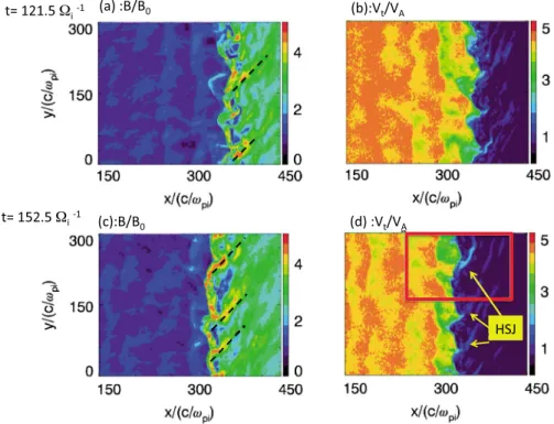
One striking feature of the present simulations is the occurrence of high-speed jets (HSJs) within the down-stream shock front region. The fact that these HSJs almost originate from the front and extend downdown-stream strongly suggests that these are related to the rippled nonstationary shock front itself as seen by comparing Figures 4a and 4b. More exactly, HSJs appear to occur solely because a parcel of incidentflow does not impinge upon a local shock surface at the same x location as an adjacent parcel offlow. HSJs are observed at different y locations. Their features can be summarized as follows : (i) these are associated toflow leaking from an adjacent location andflowing along lines parallel to intense B regions, as illustrated by dashed lines at two different times t = 121.5Ωi 1and 152.5Ωi 1in Figure 4 and more precisely by the vectorfield plot in Figure 5b; (ii) these have a
narrow structure elongated along downstream magneticfield; (iii) these persist within a certain time range and look likefilaments at a later time as these extend downstream; and (iv) their occurrence time along the shock front is mainly random without any apparent link with local self-reformation time defined in section 3.1. The associated local high-amplitude magneticfield where the HSJs originally form play the role of a secondary shock against which the incident plasmaflow suffers some deflection. The understanding of the underlying mechanisms related to HSJs, requires us to focus our attention on a detailed analysis of one HSJ.
3.2. Detailed Analysis of One HSJ
The aims of this section are to determine (i) what main process is responsible for the formation of HSJs, (ii) how a secondary shock forms, and (iii) what the main features of the HSJs are. In order to answer these questions, an enlarged view (defined by the red rectangle in Figure 4b) of a typical HSJ is shown in Figure 5, where the total magneticfield and the ion bulk velocity Vivectors are plotted at time t = 152.5Ωi 1when local downstream Vireaches a very large amplitude. The striking features are summarized as follows:
Figure 4. Isocolors of the total magneticfield (a, c) and of the ion bulk velocity (b, d) represented within the simulation plane (above view) at two different times t = 121.5Ωci 1and 152.5Ωci 1where the shock front is located around
1. The HSJ starts within the area A identified in Figure 5a where the rippled shock front presents an indenta-tion (i.e., a local strongly curved profile with a width of the order of Δy = 40c/ωpiidentified by the red arrow) facilitating any downstream penetration of the incident ionflow. Within this area A (reported in Figure 5b), a particular feature is that the upstream local ionflow vectors (indicated by dark arrows in Figure 5b) at/very near the frontier between green-blue areas are almost directed along the local shock normal but change direction when passing through this frontier (their amplitude slightly decreases as seen by theflow vectors size).
2. At a short distance from A, the ionflow meets the obstacle formed by the Ssh structure (this feature identified by a red arrow in Figure 5a will be described below). The local angle (hereafter, named α) defined between the local ion flow vectors and the local shock normal at the Ssh is very large; this feature will be analyzed in section 3.3. Then, theflow suffers a much stronger deflection farther downstream (point B) and gets a narrowfilamentary structure (indicated by arrow C in Figure 5b) elongated along the direction of the magnetic field vectors when penetrating even more downstream (to compare Figures 5a and 5b). Note that the amplitudes of both the ionflow Viand of the total magneticfield (given by the size of the local vectors) are the largest within thisfilament. The direction of this filament becomes strongly oblique with respect to the x axis (its initial direction) and deflects to the y axis (shock front direction). One stressing point is that this strong deflection takes place exactly at the location where the amplitude of local magneticfield is quite large and plays the role of a local secondary shock (named “Ssh” hereafter and in Figure 5a), as illustrated by the reference oblique dashed line plotted in both Figures 5a and 5b.
3. Farther downstream (point D), the amplitude of theflow velocity is lower than at location A (the size of the Vivector progressively decreases from A to D in Figure 5b), while it becomes more aligned along the shock front itself (following the direction of the local downstream magneticfield). In the present case, the global deflection of the ion flow from the shock normal (x axis) to the direction parallel to shock front (y axis) takes place over a distanceΔx = 36c/ωpi= 0.56 Re (the width of the spatial range between the vertical dash-dotted lines in Figure 5b). This distance should not be confused with the width (transverse scale) of HSJ discussed in section 3.3 and Table 1. The overall formation and dynamics of the HSJ may be seen in Movie S1 in the supporting information.
One question arises: How can such a secondary shock form?
Global hybrid simulations [Omidi et al., 2005; Blanco-Cano et al., 2009; Von Alfthan et al., 2014; Kempf et al., 2015] have been made recently and evidenced the wavy and turbulent activity of the quasi-parallel region and associated foreshock. But answering the above question requires a careful and local analysis of the front and of the secondary shock at times before it forms. As a reminder, the quasi-parallel shock front can be
Figure 5. Enlarged view of (a) the total magneticfield (vectors and isocolors) and (b) the ion bulk velocity Vi(vectors and isocolors) within an area containing a large high-speed jet (HSJ) at time t = 152.5Ωci 1. The selected area corresponds to
the red rectangle shown in Figure 4d. The size of local arrows used in Figures 5a and 5b is proportional to the amplitude of the total magneticfield and the ion bulk flow Vi, respectively. The vertical dash-dotted lines (within which the HSJ is
considered as a patchwork of monolithic large-amplitude magneticfield patterns. These patterns have been analyzed in detail for two decades and result from the interaction of upstream wave and a gradient in the suprathermal particle pressure [Giacalone et al., 1993; Dubouloz and Scholer, 1995; Scholer et al., 1993, 2003]. More exactly, Scholer [1993] found that when the characteristic scale length of the density gradient becomes of the same order as the wavelength of the ULF waves, the ULF wave shrinks, strongly increases in amplitude, and evolves into a pulsation-like wave packet structure named SLAMS (short large-amplitude magnetic structure). These monolithic patterns have an amplitude larger by a few orders than that of the backgroundfield. More precisely, the magnetic field compression ratio between peak values within SLAMS to upstream average must exceed a factor of 2 [Schwartz et al., 1992; Lucek et al., 2004, 2008; Wilson et al., 2013], and SLAMS have smaller spatial scales than ULF waves [e.g., Lucek et al., 2002, 2004, 2008]. These SLAMS form an ensemble of discrete structures emerging from surrounding fluctuations and constitute the basic ingredients of the quasi-parallel shock [Schwartz and Burgess, 1991; Burgess et al., 2005]. In short, new waves generated upstream grow and steepen as these are carried back toward the shock by the solar wind and replace the previous (older) SLAMS which are transmitted downstream [Burgess, 1989; Schwartz and Burgess, 1991; Schwartz et al., 1992; Mann et al., 1994].
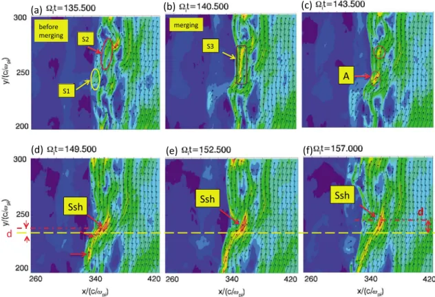
In the present case, let us analyze more carefully the wavefront dynamics. One starts at a time before the time of Figure 6 (results not shown here) when new ULF waves have reached a nonlinear level and approach the shock front. But the shock front itself already has some“old” rippling that interacts with incident flow; the label old refers to old ULF waves having already interacted with the shock front and contributed to the rippling. Then, the front of these“new” ULF waves splits into different pieces (mainly aligned along the y axis) when interacting with the old rippling, which are carried through the front by the incident plasmaflow. The upstream edge of these pieces of ULF waves suffer an important steepening and evolve into SLAMS. These SLAMS-like structures overcome one another depending on the local magnetic field amplitude at their upstream edge. Some areas can form where these pieces of the shock front accumulate (local magneticfield pileup) while being carried by the incidentflow and merge. The resulting local increased magnetic field penetrates the shock more easily (as illustrated by red ellipses in Figure 6c) and form a large-amplitude secondary shock (named Ssh) locally downstream. In contrast, other areas with much weaker local magnetic field form around the Ssh (more exactly in the wake of Ssh); then, such local depletion in the B field amplitude which facilitates the local penetration of incident plasma within the deformed front may persist and allow the upstream plasma to interact directly with the local Ssh at later times. A local larger rippling in the magnetic field profile means an increased curvature of the local ripple, i.e., a larger angle between the incident flow and the local normal to the shock, which is an appropriate condition for initiating HSJs downstream [Hietala et al., 2009].
This scenario is illustrated by the plots of the total magneticfield shown at different times of Figure 6. At t = 135.5Ωi 1(Figure 6a), some SLAMS-like pattern S1 (not shown at previous times) reach the shock front and approach a part of the front (S2 in red ellipse). A merging takes place, and the local magneticfield is strongly reinforced but is not uniform (in strength and in direction) along the y axis (S3 in purple rectangle) and leads to an elongated structure (t = 140.5Ωi 1in Figure 6b). Under convection, this structure splits into
different pieces; one piece penetrates more through the shock front and a local indentation (i.e., a local curved profile in B) forms, which corresponds to the location A of Figure 6c. The size of the indentation increases, and other surrounding pieces approach each other and merge (t = 149.5Ωi 1in Figure 6d). This merging (or B pileup process) reinforces the local magneticfield which penetrates more downstream and becomes a secondary shock (Ssh). Under the convection effects, the Ssh moves as illustrated by the increasing distance d (measured along the y axis) defined between the local maximum of B of the Ssh
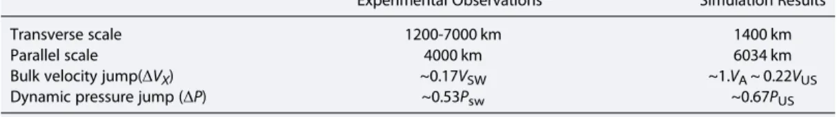
Table 1. Spatial and Time Scales Characteristic of the HSJ Analyzed in Section 3.3 at Time t = 152.5Ωci 1Within the Range 260< x/(c/wpi)< 420 and 200 < y/(c/wpi)< 300
Experimental Observationsa Simulation Results
Transverse scale 1200-7000 km 1400 km
Parallel scale 4000 km 6034 km
Bulk velocity jump(ΔVX) ~0.17VSW ~1.VA~ 0.22VUS
Dynamic pressure jump (ΔP) ~0.53Psw ~0.67PUS
(indicated by the mixed red line) and the yellow line used as a reference (Figures 6d–6f); this shift requires further analysis. Note that this Ssh does not require any obstacle to be formed and forces the initial ionflow to be strongly deflected.
As shown in Figure 5b, the HSJ is an elongatedfilamentary structure of the ion flow allowing the penetration of energetic ions within the downstream shock region. Thisfilamentary pattern is also quite evident in the ion kinetic energy as illustrated in Figures 7a and 7b. The signature is much stronger in the parallel component than in the perpendicular one, since the HSJ is strong and mainly aligned along the local downstream magneticfield.
3.3. Comparison of Simulation Results With Previous Works
Features of HSJ presented in the present work are very similar to those of the so-called transient ionflux enhancements reported in observations performed in the Earth’s magnetosheath by Němeček et al. [1998]. Similar observations have been also found with the 120 events of anomalous high energy density analyzed by Savin et al. [2008], where energy density has been defined by Wk= 0.5mpNV2and where mpis the proton mass, N is the number density, and V is the bulk velocity.
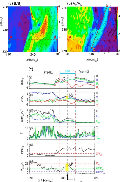
A more detailed analysis may be performed by comparing the present results with THEMIS observations made by Plaschke et al. [2013]. For this purpose, we plot in Figure 8c the spatial profile of six quantities measured along the line A-B indicated in Figures 8a and 8b, namely, (i) the magneticfield components and the associated total magneticfield; (ii) the ion bulk velocity components and the associated total Vivelocity; (iii) the parallel,
perpendicular, and total ion kinetic energy; (iv) the parallel, perpendicular, and total ion temperature; (v) the ion density; and (vi) the x component of the ion dynamic pressure, namely, Pdyn,x=ρVx2(whereρ is the plasma
density and Vxis the ion bulkflow along x). Results of Figure 8c are in a good agreement with experimental
results of Figure 1 in Plaschke et al. [2013]. More precisely, a detailed analysis shows that
Figure 6. Enlarged view of the total magneticfield (vectors and isocolors) at various times (a) t = 135.5, (b) t = 140.5, (c) t = 143.5, (d) t = 149.5, (e) t = 152.5, and (f) t = 157Ωci 1showing the formation of the secondary shock (named“Ssh”). The horizontal yellow dashed line (Figure 6d–6f) is used as a reference for the
loca-tion of the resulting secondary shock. Note that the same color spectrum is used for all times in order to appreciate the relative amplitude change of the local magneticfield in its different structures (S1, S2, S3, Ssh). The distance d (measured along the y axis) is defined between the local maximum of B of the Ssh (indicated by the dash-dotted red line) and the yellow line used as a reference.
1. The present simulation results clearly show that relative to the ambient downstream medium, the HSJ exhibits higher bulk velocity speed, density, and magnetic field. Note that values within pre-HSJ and post-HSJ regions are not identical as in Plaschke et al. [2013] where HSJ is fully imbedded within the magnetosheath far from the shock front. Indeed, in the present case, the HSJ is relatively near the shock front (the pre-HSJ region almost includes a part of the upstream region) which explains this asymmetry. 2. The most noticeable feature of the HSJ is the isolated jump in the ion dynamic pressure Pdyn,x=ρVx2(plot
(vi)). This feature is characteristic of HSJ since the plasma dynamic pressure in the downstream region has generally an amplitude much lower than that in the upstream plasma. Presently, the dynamic pressure along x within the HSJ exceeds half the upstream dynamic pressure PUS/2. The maximum pressure is
located at x = Lmax, the associated pressure jumpΔP = 0.67Psw(yellow area in Figure 8c-vi) i.e., its
maxi-mum reaches almost the upstream value PUS, while it is slightly above the upstream value PUS in
Plaschke et al. [2013]. The HSJ spatial transverse width (measured between the vertical dashed red lines in Figure 8c) is defined by the spatial range around Lmaxwhere Pdyn,x> 0.25PUSsimilar to the reference
procedure used for Figure 1 of Plaschke et al. [2013]. The measured transverse scale is equal to 14c/ω
pi= 1400 km (based on a typical value of the upstream ion inertia length c/ωpi= 100 km).
3. Inside the HSJ, the ion bulk velocity in x direction (blue line in Figure 8c-ii between vertical dashed lines) exhibits a jumpΔVx= VX(Lmax) 0.5 * VX(Lmax) = 1.0VA= 0.22VUS. In addition to Plaschke et al. [2013], the
present results show that the HSJ is shifted in time to larger y values as evidenced in the relative motion of Ssh mentioned in section 3.2 (to see the increasing distance d defined at different times in Figures 6d–6f). 4. The transverse and parallel scales of the HSJ have been measured respectively along the cuts AB and CD applied to the total ion velocity (Figure 8b), and results are reported in Table 1 (for comparison, experimental measurements are extracted from Plaschke et al. [2013]). These measurements are performed at given time t = 152.5Ωi 1, and values may vary versus time. However, these typical values are of the same order as of
those measured experimentally and a reasonable agreement is found. A good agreement is also found with experimental results of Archer et al. [2012] where spatial dimensions are of the order of 1 Re parallel to theflow and 0.2–0.5 Re perpendicular to it (from THEMIS observations). Extensively, our simulations confirm the localized temporal nature of HSJs: scales of Table 1 are in good agreement (i) with Interball-1 and Magion measurements made by Němeček et al. [1998] who found a duration (crossing time range) of the transient events varying from tens of seconds to a few minutes (corresponding dimensions of the order of 1 Re), (ii) with THEMIS observations made by Archer and Horbury. [2013] with a duration 10 s to 3 min (average around 30 s), and (iii) with an average duration of 28 s (corresponding to 1 Re) from Interball-1 observations (83 events) made by Savin et al. [2008] in structures that the authors call“high-kinetic energy density plasma jets.” Let us mention that a one to one precise agreement cannot be obtained since some experimental data are not accessible and plasma parameters may differ (for instance, MA = 12 in Hietala et al. [2009], while MA = 5.5 herein). Moreover, as mentioned by Plaschke et al. [2013] for experimental observations, let us recall two points: (a) temporal and spatial length scales depend on the chosen threshold level of the dynamic
Figure 7. Enlarged view of the (a) parallel and (b) perpendicular kinetic energy (directions are defined with respect to the local magneticfield) at the time 152.5 Ωci 1within the same spatial range as used in Figure 6.
pressure ratio used for defining the HSJ intervals (here one uses Pdyn,x> 0.25PUSin order to determine the HSJ
interval as in Plaschke et al. [2013]), and (b) the accuracy of the measured spatial scales depends on how well the jet patterns (local enhancement of Pdyn,x) follow the plasmaflow (presently, simulation results confirm
that it is the case, when comparing Figures 8c-ii and 8c-vi).
Figure 8. Isolored plots (enlarged view) of (a) the total magneticfield B and (b) the total ion bulk velocity Viat time
t = 152.5Ωci 1. The segment A-B indicates the location of the cut through the HSJ along which the spatial profiles of
different quantities are reported in Figure 8c which shows the profiles of (i) the magnetic field components Bx(x), By(x), Bz(x),
and the associated total magneticfield Bt(x), (ii) the ion bulk velocity components and the associated total Vtvelocity
(ΔVx= VX(Lmax) 0.5*VX(Lmax)), (iii) the parallel E//, perpendicular Eperp, and total (Ek) ion kinetic energy, (iv) the parallel T//,
perpendicular Tperp, and total Ttion temperatures, (v) the ion density N/NO, and (vi) the x component of the ion dynamic
pressure Pdyn,x=ρVx2(corresponding upstream values PUS, PUS/2, and PUS/4 are shown in red, green, and blue);ΔP = Pdyn,x
5. As mentioned by Plaschke et al. [2013], experimental observations do not evidence any distinct time of recurrence (i.e., time between two consecutive HSJs identified within the same magnetosheath interval). This result seems also in qualitative agreement with the present simulation results which show that the occurrence of HSJs is transient; indeed, no regular (or periodic) occurrence has been identified in the present simulations. 6. No heating is associated with HSJs as is evidenced between vertical dashed lines in Figure 8c-iv. Relative to the ambient magnetosheath, the temperature is more isotropic and even lower within the HSJ than outside in good agreement with experimental results [Plaschke et al., 2013].
Another comparison may be performed between the present simulation results and the scenario for HSJ’s formation as proposed by Hietala et al. [2009]. In contrast with Němeček et al. [1998] and Savin et al. [2008] who did not identify a clear source for the HSJs (but only invoke a local reconnection process), Hietala et al. [2009] have proposed a scenario for HSJ’s formation based on Cluster experimental observations. The key points of the scenario are (a) the presence of front rippling which allows the front to be locally curved and (b) the angleα between the upstream bulk velocity VUSand the local shock normal N. When this local
angleα is small, the shock primarily decelerates the flow VUS. However, when the local angleα is large
(due to the curvature of local large-scale rippling), the curved shock mainly deflects the flow while the plasma bulk velocity is almost close to its upstream value. Then, the plasma is compressed (with respect to the sur-rounding values) in such a way that the local high density combined with the high bulk velocity results in a jet with a high dynamic pressure [Hietala et al., 2009].
This scenario is quite similar to the one that we obtain in the present simulation (section 3). However, let us note some slight differences: (i) our results show that the ion bulk velocity within the HSJ (Figure 8c-ii) suffers some decrease with respect to its upstream value (instead of being constant); (ii) Figure 3 of Hietala et al. [2009] (and Figure 1 of Hietala et al. [2012]) invoke the formation of a secondary shock upstream of an obstacle, in relation to the fact that the HSJ is observed close to the magnetopause, due to its interaction with the magnetopause. The magnetosheath HSJ was supermagnetosonic in the frame of reference of the magnetopause, and thus it formed a shock upon interaction. The simulations of Karimabadi et al. [2014] also indicate the possibility of formation of a bow wave/shock ahead of a supermagnetosonic HSJ as it propagates deeper into the magne-tosheath. Moreover, the present results stress the importance of the“secondary shock” (named Ssh) which forms within the shock front and of the angleα defined more precisely between the local bulk velocity VUS (upstream of this Ssh) and the local shock normal N at this Ssh. However, let us emphasize that the Ssh mentioned in the present study only results from a rapid pileup of nonlinear (SLAMS-like) curved structures at the front, which leads to a rapid enhancement of a local magneticfield; no obstacle has been invoked. At last, our present Ssh is located much closer to the main shock, which suggests that this difference is due to the smaller Mach regime (MA = 5.5) used herein as compared to that measured by Hietala et al. [2009] where MA = 12 or by Karimabadi et al. [2014] where MA = 8. These differences are in agreement with the idea that HSJs associated with high MA regime of solar wind can penetrate farther downstream (with a bulk velocity closer to its upstream value) and reach more easily the magnetopause than for lower MA regimes.
In summary, a good agreement has been found between the present simulation and previous experimental results [Hietala et al., 2009, 2012; Plaschke et al., 2013] which seems to clearly indicate that HSJs are issued from the shock front rippling in association with the shock front nonstationarity. Of course, this does not mean that all previously reported HSJs are issued from the same geometry-related origin.
4. Conclusions
The present simulation results confirm and detail the formation of HSJs, where the flow in the downstream region of a quasi-parallel shock is well structured (filamentary pattern). The main features of these structures may be summarized as follows:
1. HSJs form at the front and propagate and extend within the downstream region. Their occurrence is transient and is independent of local self-reformation processes.
2. Their formation is strongly associated to the nonstationary behavior and the strong rippling (local curvature effects) of the shock front, which allows a deeper penetration of the incident ionflow into the downstream region.
3. HSJs result as the initial ionflow deflects away from the shock normal to a strongly oblique direction approaching the shock front, as it penetrates farther downstream.
not need any external upstream pressurefluctuations/discontinuities imbedded in and carried by the solar wind to be generated. Several scenarios for their formation have been proposed by different authors: (i) Lin et al. [1996a, 1996b] have analyzed the interaction of the bow shock with a rotational discontinuity moving in the interplanetary field by using hybrid and magnetohydrodynamic models; (ii) Savin et al. [2008, 2012] have proposed that the hotflow anomalies (representing obstacles to the flow of the solar wind) may locally trigger HSJs to reestablish the solar wind balance; and (iii) Hietala et al. [2009, 2012] have pro-posed a scenario where HSJs are generated by the shock front rippling (local curvature effects) combined with the nonstationarity of the shock front. Indeed, nearby local disturbances such as SLAMS-like or isolated upstream structures (self-consistently generated upstream of the shock by instabilities and interaction with suprathermal reflected ions) can penetrate downstream under the convection effects. The present results are in a good agreement with this last proposed scenario and with previous experimental observations based on THEMIS and Cluster data. Let us note that recent numerical results issued from 2-D global hybrid simulations by Karimabadi et al. [2014] have also mentioned somefilamentary structures (named HSJs herein) which can extend till farther magnetosheath, but no detailed explanation on their formation has been given at that time. Moreover, upstream plasma conditions and Mach regime differ from those considered herein, and a further parametric analysis is necessary in order to perform a detailed comparison of previous global and the present local results. At last, let us note that a recent work of Karlsson et al. [2015] based on Cluster experimental data has evidenced two distinct populations of magnetosheath plasmoids: the so-called diamagnetic plasmoids associated to a decrease of the magneticfield strength (but no change of the magnetosheath plasmaflow velocity) and the so-called paramagnetic plasmoids associated to an increase of the magneticfield strength and which can be either embedded (to see Karlsson et al. [2012]) or associated to an increase in theflow velocity. This analysis suggests that the paramagnetic plasmoids may be regarded as a subset of HSJs or a closely related phenomenon. A further comparative analysis between these plasmoids and the HSJs is then necessary and will be developed in the near future.
References
Amata, E., S. P. Savin, D. Ambrosino, Y. V. Bogdanova, M. F. Marcucci, S. Romanov, and A. Skalsky (2011), High kinetic energy density jets in the Earth’s magnetosheath: A case study, Planet. Space Sci., 59, 482–494, doi:10.1016/j.pss.2010.07.021.
Archer, M. O., and T. S. Horbury (2013), Magnetosheath dynamic pressure enhancements: Occurrence and typical properties, Ann. Geophys., 31, 319–331, doi:10.5194/angeo-31-319-2013.
Archer, M. O., T. S. Horbury, and J. P. Eastwood (2012), Magnetosheath pressure pulses: Generation downstream of the bow shock from solar wind discontinuities, J. Geophys. Res., 117, A05228, doi:10.1029/2011JA017468.
Axford, W. I., E. Lee, and G. Skadron (1977), The acceleration of cosmic rays by shock waves, Proc. Int. Conf. Cosmic Rays 15th, 11, 132. Blanco-Cano, X., N. Omidi, and C. T. Russell (2009), Global hybrid simulations: Foreshock waves and cavitons under radial IMF geometry,
J. Geophys. Res., 114, A01216, doi:10.1029/2008JA013406.
Blandford, R. D., and J. P. Ostriker (1978), Particle acceleration by astrophysical shocks, Astrophys. J., 221, L29–L32.
Burgess, D. (1989), Cyclic behavior at quasi-parallel collisionless shocks, Geophys. Res. Lett., 16(5), 345–348, doi:10.1029/GL016i005p00345. Burgess, D., et al. (2005), Quasi-parallel shock, structure and processes, in the book“Outer Magnetospheric Boundaries: Cluster Results”,
Space Sci. Rev., 118(1-4), 206–222.
Dubouloz, N., and M. Scholer (1995), Two-dimensional simulations of magnetic pulsations upstream of the Earth’s bow shock, J. Geophys. Res., 100, 9461–9474, doi:10.1029/94JA03239.
Gary, S. P. (1992), The mirror and ion cyclotron anisotropy instabilities, J. Geophys. Res., 97, 8519–8529, doi:10.1029/92JA00299. Gary, S. P., M. D. Montgomery, W. C. Feldman, and D. W. Forslund (1976), Proton temperature anisotropy instabilities in the solar wind,
J. Geophys. Res., 81, 1241–1246, doi:10.1029/JA081i007p01241.
Gary, S. P., M. E. McKean, D. Winske, B. J. Anderson, R. E. Denton, and S. A. Fuselier (1994), The proton cyclotron instability and the anisotropyβ inverse correlation, J. Geophys. Res., 99, 5903–5914, doi:10.1029/93JA03583.
Acknowledgments
This work is supported by the National Science Foundation of China (grants 41331067, 11235009, 41274144, and 41121003), 973 Program (2012CB825602 and 2013CBA01503), and CAS Key Research Program KZZD-EW-01-4. Computer resources were provided by the National Supercomputer Center of China in Tianjin and Alabama Supercomputer Center. The authors also thank D.W. Swift for his help and discussions in the code development. The numerical data can be obtained by contacting the corresponding author via email. One of the authors (Y.H.) thanks the China Scholarship Council (CSC) for attributing a fellowship for a 1 year stay in LATMOS laboratory (Guyancourt, France) which is warmly thanked for its welcome and hospitality. The authors thank the referees for their detailed and helpful comments.
Giacalone, J., S. J. Schwartz, and D. Burgess (1993), Observations of suprathermal ions in association with SLAMS, Geophys. Res. Lett., 20, 149–152, doi:10.1029/93GL00067.
Gosling, J. T., M. F. Thomsen, and S. J. Bame (1989), Ion reflection and downstream thermalization at the quasi-parallel shock, J. Geophys. Res., 94(A8), 10,027–10,037, doi:10.1029/JA094iA08p10027.
Gunell, H., et al. (2014), Waves in high-speed plasmoids in the magnetosheath and at the magnetopause, Ann. Geophys., 32, 991–1009, doi:10.5194/angeo-32-991-2014.
Hada, T., M. Oonishi, B. Lembège, and P. Savoini (2003), Shock front nonstationarity of supercritical perpendicular shocks, J. Geophys. Res., 108(A16), 1233, doi:10.1029/2002JA009339.
Hao, Y., Q. Lu, X. Gao, C. Huang, S. Lu, L. Shan, and S. Wang (2014), He2+dynamics and ion cyclotron waves in the downstream of quasi-perpendicular shocks: 2-D hybrid simulations, J. Geophys. Res. Space Physics, 119, 3225–3236, doi:10.1002/2013JA019717. Hietala, H., and F. Plaschke (2013), On the generation of magnetosheath high-speed jets by bow shock ripples, J. Geophys. Res. Space Physics,
118, 7237–7245, doi:10.1002/2013JA019172.
Hietala, H., T. V. Laitinen, K. Andreeova, R. Vainio, A. Vaivads, M. Palmroth, T. I. Pulkkinen, H. E. J. Koskinen, E. A. Lucek, and H. Reme (2009), Supermagnetosonic jets behind a collisionless quasiparallel shock, Phys. Rev. Lett., 103, 245,001, doi:10.1103/PhysRevLett.103.245001. Hietala, H., N. Partamies, T. V. Laitinen, L. B. N. Clausen, G. Facsko, A. Vaivads, H. E. J. Koskinen, I. Dandouras, H. Reme, and E. A. Lucek (2012),
Supermagnetosonic subsolar magnetosheath jets and their effects: From the solar wind to the ionospheric convection, Ann. Geophys., 30, 33–48, doi:10.5194/angeo-30-33-2012.
Jones, F. C., and D. C. Ellison (1991), The plasma physics of shock acceleration, Space Sci. Rev., 58(1), 259–346.
Karimabadi, H., et al. (2014), The link between shocks, turbulence, and magnetic reconnection in collisionless plasmas, Phys. Plasmas, 21(6), 62,308, doi:10.1063/1.4882875.
Karlsson, T., N. Brenning, H. Nilsson, J.-G. Trotignon, X. Vallières, and G. Facsko (2012), Localized density enhancements in the magnetosheath: Three-dimensional morphology and possible importance for impulsive penetration, J. Geophys. Res., 117, A03227, doi:10.1029/2011JA017059. Karlsson, T., A. Kullen, E. Liljelad, N. Brenning, H. Nilsson, H. Gunell, and M. Hamrin (2015), On the origin of magnetosheath plasmoids and
their relation to magnetosheath jets, J. Geophys. Res. Space Physics, 120, 7390–7403, doi:10.1002/2015JA021487.
Kempf, Y., O. Gutynska, D. Pokhotelov, L. B. Wilson, B. Walsh, S. von Alfthan, D. Sibeck, and M. Palmroth (2015), Ion distributions in the Earth’s foreshock: Hybrid-Vlasov simulation and THEMIS observations, J. Geophys. Res. Space Physics, 120, 3684–3701, doi:10.1002/2014JA020519. Lembège B. (1990), Numerical simulation of collisionless shocks, in Physical Processes in Hot Cosmic Plasmas, edited by W. Brinckmann, A. C. Fabian, and F. Giovanelli, pp 81-139, NATO Advanced Research Workshop, (Vulcano, Sicile, 29 mai - 02 juin, 1989), Kluwer Acad. Publ. Lembège, B., and J. M. Dawson (1987), Self-consistent study of a perpendicular collisionless and non-resistive shock, Phys. Fluids, 30(6),
1767–1788.
Lembège, B., J. Giacalone, M. Scholer, T. Hada, M. Hoshino, V. Krasnoselskikh, H. Kucharek, P. Savoini, and T. Terasawa (2004), Selected pro-blems in collisionless-shock physics, Space Sci. Rev., 110, 161.
Leroy, M. M., C. C. Goodrich, D. Winske, C. S. Wu, and K. Papadopoulos (1981), Simulation of a perpendicular bow shock, Geophys. Res. Lett., 8, 1269–1272, doi:10.1029/GL008i012p01269.
Leroy, M. M., D. Winske, C. C. Goodrich, C. S. Wu, and K. Papadopolous (1982), The structure of perpendicular bow shocks, J. Geophys. Res., 87(A7), 5081–5094, doi:10.1029/JA087iA07p05081.
Lin, Y., L. C. Lee, and M. Yan (1996a), Generation of dynamic pressure pulses downstream of the bow shock by variations in the interplanetary magneticfield orientation, J. Geophys. Res., 101, 479–493, doi:10.1029/95JA02985.
Lin, Y., D. W. Swift, and L. C. Lee (1996b), Simulation of pressure pulses in the bow shock and magnetosheath driven by variations in interplanetary magneticfield direction, J. Geophys. Res., 101, 27,251–27,269, doi:10.1029/96JA02733.
Lu, Q. M., and S. Wang (2005), Formation of He2+shell-like distributions downstream of the Earth’s bow shock, Geophys. Res. Lett., 32, L03111, doi:10.1029/2004GL021508.
Lu, Q. M., and S. Wang (2006), Electromagnetic waves downstream of quasi-perpendicular shocks, J. Geophys. Res., 111, A05204, doi:10.1029/ 2005JA011319.
Lucek, E. A., T. S. Horbury, M. W. Dunlop, P. J. Cargill, S. J. Schwartz, A. Balogh, P. Brown, C. Carr, K.-H. Fornaçon, and E. Georgescu (2002), Cluster magneticfield observations at a quasi-parallel bow shock, Ann. Geophys., 20, 1699–1710.
Lucek, E. A., T. S. Horbury, A. Balogh, I. Dandouras, and H. Rème (2004), Cluster observations of structures at quasi-parallel bow shocks, Ann. Geophys., 22, 2309–2314.
Lucek, E. A., T. S. Horbury, I. Dandouras, and H. Rème (2008), Cluster observations of the Earth’s quasi-parallel bow shock, J. Geophys. Res., 113, A07S02, doi:10.1029/2007JA012756.
Mann, G., H. Lühr, and W. Baumjohann (1994), Statistical analysis of short large-amplitude magneticfield structures in the vicinity of the quasi-parallel bow shock, J. Geophys. Res., 99, 13,315–13,323, doi:10.1029/94JA00440.
Mazelle, C., et al. (2003), Production of gyrating ions from nonlinear wave-particle interaction upstream from Earth’s bow shock: A case study from Cluster-CIS, Planet. Space Sci., 51, 785–795.
McKean, M. E., N. Omidi, and D. Krauss-Varban (1995a), Wave and ion evolution downstream of quasi-perpendicular bow shocks, J. Geophys. Res., 100, 3427–3437, doi:10.1029/94JA02529.
McKean, M. E., N. Omidi, D. Krauss-Varban, and H. Karimabadi (1995b), Wave and particle evolution downstream of quasi-perpendicular shocks, Adv. Space Res., 15, 319–322.
McKean, M. E., N. Omidi, and D. Krauss-Varban (1996), Magnetosheath dynamics downstream of low Mach number shocks, J. Geophys. Res., 101, 20,013–20,022, doi:10.1029/96JA01461.
Němeček, Z., J. Šafránková, L. Přech, D. G. Sibeck, S. Kokobun, and T. Mukai (1998), Transient flux enhancements in the magnetosheath, Geophys. Res. Lett., 25, 1273–1276, doi:10.1029/98GL50873.
Ofman, L., and M. Gedalin (2013), Two-dimensional hybrid simulations of quasi-perpendicular collisionless shock dynamics: Gyrating downstream ion distributions, J. Geophys. Res. Space Physics, 118, 1828–1836, doi:10.1029/2012JA018188.
Ofman, L., M. Balikhin, C. T. Russell, and M. Gedalin (2009), Collisionless relaxation of ion distributions downstream of laminar quasi-perpendicular shocks, J. Geophys. Res., 114, A09106, doi:10.1029/2009JA014365.
Omidi, N., X. Blanco-Cano, and C. T. Russell (2005), Macro-structure of collisionless bow shocks: 1. Scale lengths, J. Geophys. Res., 110, A12212, doi:10.1029/2005JA011169.
Plaschke, F., H. Hietala, and V. Angelopoulos (2013), Anti-sunward high speed jets in the subsolar magnetosheath, Ann. Geophys., 31, 1877–1889, doi:10.5194/angeo-31-1877-2013.
Quest, K. B., D. W. Forslund, J. U. Brackbill, and K. Lee (1983), Collisionless dissipation processes in quasi-parallel shocks, Geophys. Res. Lett., 10(6), 471–474, doi:10.1029/GL010i006p00471.
bow shock: Specularly and non-specularly reflected-gyrating ions, J. Geophys. Res., 88(A8), 6121–6136, doi:10.1029/JA088iA08p06121. Shoji M., Y. Omura, B. T. Tsurutani, O. P. Verkhoglyadova, and B. Lembège (2009), Mirror instability and L-mode electromagnetic ion cyclotron
instability: Competition in the Earth’s magnetosheath, J. Geophys. Res., 114, A10203, doi:10.1029/2008JA014038.
Shue, J. H., J.-K. Chao, P. Song, J. P. McFadden, A. Suvorova, V. Angelopoulos, K. H. Glassmeier, and F. Plaschke (2009), Anomalous magnetosheathflows and distorted subsolar magnetopause for radial interplanetary magnetic fields, Geophys. Res. Lett., 36, L18112, doi:10.1029/2009GL039842.
Su, Y., Q. Lu, C. Huang, M. Wu, X. Gao, and S. Wang (2012a), Particle acceleration and generation of diffuse superthermal ions at a quasi-parallel collisionless shock: Hybrid simulations, J. Geophys. Res., 117, A08107, doi:10.1029/2012JA017736.
Su, Y., Q. Lu, X. Gao, C. Huang, and S. Wang (2012b), Ion dynamics at supercritical quasi-parallel shocks: Hybrid simulations, Phys. Plasmas, 19, 092,108.
Thomas, V. A., D. Winske, and N. Omidi (1990), Reforming super-critical quasi-parallel shocks, 1. One- and two-dimensional simulations, J. Geophys. Res., 95, 18,809–18,819, doi:10.1029/JA095iA11p18809.
Thomsen, M. F., J. T. Gosling, S. J. Bame, and T. G. Onsager (1990), Two-state ion heating at quasi-parallel shock, J. Geophys. Res., 95, 6363–6374, doi:10.1029/JA095iA05p06363.
Tsubouchi, K., and B. Lembège (2004), Full particle simulations of short large-amplitude magnetic structures (SLAMS) in quasi-parallel shocks, J. Geophys. Res., 109, A02114, doi:10.1029/2003JA010014.
Von Alfthan, S., D. Pokhotelov, Y. Kempf, S. Hoilijoki, I. Honkonen, A. Sandroos, and M. Palmroth (2014), Vlasiator: First global hybrid-Vlasov simulations of Earth’s foreshock and magnetosheath, JASTP, 120, 24–35, doi:10.1016/j.jastp.2014.08.012.
Webb, G. M., G. P. Zank, M. Ko, and D. J. Donohue (1995), Multidimensional Green’s functions and the statistics of diffusive shock acceleration, Astrophys. J., 453, 178–206.
Wilson, L. B., III, A. Koval, D. G. Sibeck, A. Szabo, C. A. Cattell, J. C. Kasper, B. A. Maruca, M. Pulupa, C. S. Salem, and M. Wilber (2013), Shocklets, SLAMS, andfield-aligned ion beams in the terrestrial foreshock, J. Geophys. Res. Space Physics, 118, 957–966, doi:10.1029/2012JA018186. Winske, D., and K. B. Quest (1988), Magneticfield and density fluctuations at perpendicular supercritical collisionless shocks, J. Geophys. Res.,
93, 9681–9693, doi:10.1029/JA093iA09p09681.
Winske, D., N. Omidi, K. B. Quest, and V. A. Thomas (1990), Reforming supercritical quasi-parallel shocks: 2. Mechanism for wave generation and front reformation, J. Geophys. Res., 95, 18,821, 18,832, doi:10.1029/JA095iA11p18821.
Yang, Z. W., Q. M. Lu, B. Lembège, and S. Wang (2009a), Shock front nonstationarity and ion acceleration in supercritical perpendicular shocks, J. Geophys. Res., 114, A03111, doi:10.1029/2008JA013785.
Yang, Z. W., Q. M. Lu, and S. Wang (2009b), The evolution of the electricfield at a nonstationary perpendicular shock, Phys. Plasmas, 16, 1. Yang, Z. W., B. Lembège, and Q. M. Lu (2012), Impact of the rippling of a perpendicular shock front on ion dynamics, J. Geophys. Res., 117,
A07222, doi:10.1029/2011JA017211.
Zank, G. P., G. Li, V. Florinski, Q. Hu, D. Lario, and C. W. Smith (2006), Particle acceleration at perpendicular shock waves: Model and observations, J. Geophys. Res., 111, A06108, doi:10.1029/2005JA011524.