A Device for Debridement Using High Pressure
Water Jets
MASby
Ashley Brown
Submitted to the Department of Mechanical Engineering
SACHUSETTS INSTITUTE OF TECH-NOLOGY
AUG 15 2014
LIBRARIES
in partial fulfillment of the requirements for the degree of
Master of Science in Mechanical Engineering
at the
MASSACHUSETTS INSTITUTE OF TECHNOLOGY
June 2014
@
Massachusetts Institute of Technology 2014. All rights reserved.
Author ...
Certified by...
gnature redacted
(I
Department of Mechanical Engineering
May 27, 2014
Signature redacted
Ian W. Hunter
Hatsopoulos Professor of Mechanical Engineering
Thesis Supervisor
Signature redacted
A ccepted by ...
...
David E. Hardt
Chairman, Department Committee on Graduate Theses
3
A Device for Debridement Using High Pressure Water Jets
by
Ashley Brown
Submitted to the Department of Mechanical Engineering on May 27, 2014, in partial fulfillment of the
requirements for the degree of
Master of Science in Mechanical Engineering
Abstract
Removing devitalized tissue from chronic wounds through debridement is critical to promote wound healing. In this thesis, technology using high-speed water jets is explored toward applications for debridement. After presenting possible techniques, the thesis expands on one promising method using two impinging cutting jets that is further developed and demonstrated on simulated necrotic tissue. Surgical blades are used to score the tissue in advance of the nozzles. Vacuum suction is applied to locally evacuate waste. At optimal parameters of 75 pm orifices spaced 2 mm apart at 1100, the device was able to excise soft necrotic tissue at 6 MPa. This configuration was able to make side-by-side excisions and caused no visible damage to the surrounding tissue. Furthermore, preliminary tests suggest that the device does not propagate bacteria into soft tissue. Suggestions for improvements to this technology are given, particularly with respect to accidental injection of water into cut tissue. The data suggests that the device shows promise as a debridement technique.
Thesis Supervisor: Ian W. Hunter
5
Acknowledgments
First, I would like to thank my advisor Professor Ian Hunter for giving me to oppor-tunity to work in his lab the past three years. I have learned a tremendous amount here and I am inspired on a daily basis.
I would also like to thank Dr. Cathy Hogan for her guidance and mentorship throughout this project. She continually pointed me towards key insights, guided me in the next step of experimentation, and trained me in the scientific process. My technical and investigative skills have substantially grown through her influence.
The members of the Bioinstrumentation lab, thank you both for your friendship and for sharing your considerable expertise. Thank you to Ashin Modak and John Liu for your efforts in editing this thesis, and to Brian Hemond and Mike Nawrot for your helpful insights. Kate, thank you for making the research a smooth and enjoyable process. Thank you Alison Cloutier for your friendship and encouragement.
This research was supported in part through the NSF Graduate Research Fellow-ship and 3M.
Thank you Marcel Thomas for motivating me to be a better engineer.
To my parents, I think you two are amazing and I am immensely grateful for all the support you have given me in every way. Thank you for introducing me to my God, who means everything to me.
Contents
Contents
1 Introduction 2 Background
2.1 Wound Healing Process ... ... 2.2 Chronic Wounds and Wound Bed Preparation . . .
2.2.1 Lavage ...
2.2.2 Debridement Techniques ...
2.3 Cutting Mechanics and Fluid Jets . . . . 2.4 Jet Injection with a Linear Lorentz-Force Actuator
3 Development of Cutting Concept
3.1 Experimental Setup to Supply High Pressure
3.2 Initial Cutting Concepts . . . . 3.2.1 Description of Initial Concepts . . . .
3.2.2 Experimental Setup . . . .
3.3 Simulating a Sloughy Wound . . . .
3.4 Experimental Testing of Initial Concepts . .
W ater . . . .
4 Dual Nozzle Cutting Instrument
4.1 Device Description . . . . 7 7 9 11 11 12 13 13 14 19 23 23 27 27 30 32 33 39 39
4.2 Cutting with Two Nozzles in a Tissue Analog . . . . 47
4.3 Cutting Necrotic Tissue . . . . 50
4.3.1 Simulating and Cutting Hard Eschar . . . . 52
4.3.2 Cutting Sloughy Wounds . . . . 55
5 Optimizing Design for Cutting Necrotic Tissue 63 5.1 Vacuum to Evacuate Tissue and Water . . . . 65
5.2 Reducing Water Injection . . . . 69
5.2.1 Increasing Speed of Cut . . . . 72
5.2.2 Shortening Nozzle Distance . . . . 73
5.2.3 Pre-cutting with a Surgical Blade . . . . 79
5.3 Assessing if Bacteria are Driven into Tissue . . . . 88
6 Conclusions and Future Work 91
Bibliography 95
Chapter 1
Introduction
The care of chronic wounds is a significant burden both on the healthcare system, costing $25 billion annually in the US [1], and on the patient, causing pain and limiting activity [2]. An estimated 3 to 6 million American are affected by chronic wounds, many of which are ulcers associated with restricted blood flow, diabetes mellitus, or pressure [3]. Treatment is frequently unsuccessful, with only an estimated 25 to 50% of venous and diabetic ulcers closing after twenty weeks of treatment [4].
Debridement, the removal of necrotic tissue and foreign materials from wounds, is a crucial component in chronic wound care [5]. While there exist many debridement techniques, the search for new and more effective methods is ongoing [6].
This thesis presents the development of a novel debridement device that uses two high speed jets to excise necrotic tissue. Chapter 2 gives background on wound care and the mechanics of cutting with jets. Chapter 3 describes the generation and testing of debridement concepts. Chapter 4 presents the design and performance of a two-nozzle device, and Chapter 5 details further tests with and improvements to this device. Finally, Chapter 6 discusses the device capabilities and future work.
Chapter 2
Background
2.1
Wound Healing Process
Human skin consists of two layers. The outer epidermis acts as a protective barrier, shielding the dermis beneath. In addition to nourishing the epidermis, the dermis provides a supporting structure through a collagen-rich extracellular matrix [7].
Acute wounds are breaches of the epidermis caused by trauma or surgery that heal in four overlapping stages [8][9]. After the initial tissue breach, the coagulation phase begins, during which a clot of platelets and cross-linked fibrin protein halt bleeding. In the inflammation phase, chemical signals attract inflammatory cells from the circulating blood. Neutrophils remove contaminating bacteria and macrophages clear the remains of damaged cells and matrix. Cell proliferation occurs when new capillaries penetrate the clot, allowing granulation tissue to form [7]. Fibroblasts
fill the injury with a provisional wound matrix while epithelial cells multiply at the
wound edge and migrate across the granulation tissue, forming a new epidermis [7]. Finally, remodeling continues for several weeks with synthesis of new extracellular matrix and apoptosis of unneeded cells. The wound healing process can take up to several months [8].
2.2
Chronic Wounds and Wound Bed Preparation
Chronic wounds fail to re-epithelialize and are locked in the inflammatory phase of wound healing [5][6]. In chronic wounds, devitalized tissue in the form of either a dry eschar or moist slough (Fig. 2-1) stimulates pro-inflammatory signals and blocks the migration of healthy cells into the wound bed [5]. This necrotic tissue provides a environment for bacterial proliferation, increasing the risk of infection [10].
A
B
Figure 2-1: Two types of necrotic tissue. (A) is a wound with slough, a soft mass of devitalized tissue, frequently yellow in color. (B) shows a wound with dry and hard necrotic tissue, eschar. The redness surrounding this wound may indicate infection. Photos reproduced from [11].
An important concept in treating chronic wounds is wound bed preparation, the goal of which is to restore the environment of an acute wound by debridement, man-agement of exudate, and regulation of the bacterial load [10]. The removal of devital-ized tissue and foreign materials in conjunction with abundant lavage decreases the risk of infection [6].
2.2.1
Lavage
During lavage, a wound is irrigated with fluid in order to remove bacteria and par-ticulates [5][12]. Lavage can be delivered at low pressures, generally defined as 9 to
100 kPa, or at high pressures between 240 and 480 kPa [12]. Although high pressure
lavage can remove contaminants [13], the technique damages soft tissue [14]. Ad-ditionally, high pressure lavage drives bacteria to penetrate into soft tissue, leading many to recommend low pressure lavage as the preferred method for bacterial removal [12].
2.2.2
Debridement Techniques
Five well-established methods are used for debridement [6][5]:
Sharp Debridement is the excision of necrotic tissue with a scalpel or scissors
[15]. Although considered the best technique for fast removal of large amounts of
necrotic tissue, sharp debridement does not allow for selective removal of devitalized tissue [6]. Surgeons are taught to debride the wound until it bleeds [1], and blood loss is a problem in some patients [16]. Performing this technique requires training in surgical debridement [5] and is costly [17].
Mechanical Debridement involves placing wet-to-dry dressings on the wound.
When the dry dressing is removed, so is the top layer of tissue. This method removes healthy as well as necrotic tissue and can be quite painful [18].
Autolytic Debridement uses the bodys own tissue-degrading enzymes to
selec-tively break down necrotic tissue. Moist dressings are applied to wounds to stimulate production of these enzymes. This technique can be prohibitively slow [5].
Enzymatic Debridement is the introduction of enzymes such as collagenase to
the wound bed in order to break down the damaged extracellular matrix [5].
Larval Therapy uses the sterile larvae of the green bottle fly to dissolve necrotic tissue using enzymes in their saliva. The maggots use the devitalized tissue as a food
source. Larval therapy is faster than autolytic debridement [19].
Each method has advantages and drawbacks which are summarized in Table 2.1. The most appropriate treatment depends on the patient, the wound, and the available resources [5].
Table 2.1: A comparison of common debridement techniques, where 1 is the most
appropriate and 4 is the least appropriate. Adapted from [17].
Autolytic Surgical Enzymatic Mechanical
Speed 4 1 2 3 Tissue Selectivity 3 2 1 4 Painful Wound 1 4 2 3 Exudate 3 1 3 2 Infection 4 1 3 2 Cost 1 4 2 3
A relatively new debridement technique, hydrosurgery, uses a narrow saline jet
to simultaneously lavage and debride soft tissue [20][21]. The VersajetTM selectively removes necrotic tissue using a sterile saline jet directed parallel to the wound surface [21]. The high velocity stream causes a local decrease in pressure by the venturi effect, drawing the targeted tissue into the cutting path (Fig. 2-2). The device is lauded for its speed, ease of use, and ability to reduce bacterial load [22]. However, because the device relies on suction to deform tissue into the cutting path, it is unable to debride hard eschar. Furthermore, the technique's slow material removal rate makes it a poor choice for debriding deep burn wounds or other wounds with a large volume of necrotic tissue [20].
2.3
Cutting Mechanics and Fluid Jets
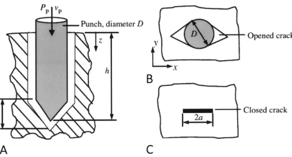
Shergold et al. showed that when a liquid jet breaches a soft material, it opens a planar crack, comparable to the behavior observed using sharp-tipped punches [25]. As illustrated in Fig. 2-3, the crack closes after the punch is removed. A review
Figure 2-2: The Versajet Hydrosurgery SystemT M directs a single jet parallel to the wound surface. The venturi effect draws soft tissue into the jet path, where it is cut and evacuated [21]. Figure adapted from [23] and [24].
of injection injuries and jet injection devices suggests that 15 MPa is required to puncture human skin with a liquid jet of diameters between 100 and 500 Pm, though this pressure has been shown to increase as jet diameter decreases. Larger loads and greater deformations are required to initiate this crack than to propagate it [25].
Using fracture mechanics to model cuts in deformable bodies gives insight into the mechanisms of crack formation by liquid jet impingement. In a deformable body, a sufficiently sharp tool causes only local deformation. Neglecting friction, cutting with a sharp tool in has been modeled using fracture mechanics as having three modes, shown in Fig. 2-4: (1) deformation, where work from the cutting tool is stored as elastic energy in the deformed body, (2) rupture, where the stored elastic energy irreversibly goes into initiating a fracture, and (3) cutting, where further work from the cutting tool goes into propagating the fracture [26].
Empirical correlations show that the stress necessary to perforate tissue increases with Young's modulus, which one study measured as 0.3 MPa in human skin and 0.5
Punch, diameter D h
A
Opened crackB
Closed crackC
Figure 2-3: Both liquid jets and sharp-tipped punches open a planar crack when they
penetrate tissue, as depicted in cross-section in (A) and from above in (B). In (C), the planar crack closes after the punch is removed. Reproduced from [25].
A
Figure 2-4: An illustration of cutting with a sharp tool in a deformable solid, where a straight segment symbolizes a wall of the original body or a wall created by fracture and a curved segment symbolizes a wall subject to deformation. In (A), a sharp tool causes elastic deformation. In (B), the energy stored in the elastic deformation goes into rupturing the solid, and a fracture is initiated. In (C), the sharp tool deepens the crack through cutting, where energy from the cutting tool goes into propagating the fracture. Adapted from [26].
16
MPa in porcine abdominal tissue [27]. Tissue stiffness decreases, however, if thermal damage degrades the crystalline structure of the dermal collagen into a gel-like state. Tissue dehydration, by contrast, causes an increase in stiffness [28]. Therefore it is expected that in tissue with degraded collagen, such as sloughy tissue, a lower jet pressure will be needed to penetrate, while dry samples such as eschar will have a higher penetration pressure.
After penetration, the liquid jet slows and stagnates. As Fig. 2-5 illustrates, upon stagnation a bolus of liquid expands spherically outwards from the end of the hole into the surrounding tissue [29]. Thus, less pressure is required to disperse the liquid into the tissue than to bore the hole.
Schramm-Baxter and Mitragori [30] showed that the depth of jet penetration and the width of liquid dispersion both correlate to the power of the jet, given by
1.
PO = 1Tu (2.1)
where P is the power of the jet at the nozzle exit, 7h is the mass flow rate, and
uO is the exit velocity. The mass flow rate can be given as
m = pAouo, (2.2)
where p is the fluid density and AO is the area of the nozzle orifice. Plugging the mass flow rate of Eq. 2.2 into Eq. 2.1 yields the equation for jet power
PO = 2U. 23rpD (2.3)
Experimental data are reproduced in Fig. 2-6 that shows that that both hole depth and the width of dispersion increase with jet power in a logarithmic manner
[30].
Lastly, the jet exit velocity can be estimated from the supplied pressure Psupply
using Bernoulli's equation,
K
Injector
Epidermis
Dispersion
Dermis
L.
.
.
.
.
.
.
.
.
.
.
.
.
.
..
.
.
.
.
.
.
.
.
.
.
.
.
.
..
.
.
.
.
.
.
.
.
.
.
.
.
.
.
.
.
..
...
.
.
.
.
.
.
.
.
.
.
.
..
.
.
.
.
.
.
..
.
.
.
.
.
.
. ...
...
.
.
.
.
.
...
.
.
.
.
W.
E.
.
..
.
..
.
.
.
.
.
.
.
.
.
.
.
.
. . . ..... ... ... .. .. ... .. .... .. .... ... ... ... ... . . . . . . . . . . . . . . . . . . . . . . . . . . . .Deposition
Figure 2-5: During jet injection, the liquid jet slows as it penetrates further into the sample. When the jet stagnates, it expands water spherically outwards into the tissue, as shown above. Reproduced from [29].
18
A
B
10 3.5 3-2.5 -6 -2--14
J1.5 2 --0.5 0 g 0 1 10 100 1000 10 100 1000Power at nozzle exit (W) Power at nozzle exit (W)
Figure 2-6: Experimental data showing that both the depth of injection and the width of dispersion Lm produced by a liquid jet in tissue scale logarithmically with jet power. Reproduced from [30].
O= 2pqupply (2.4)
VP
which in one study was found to predict more accurately than several friction
models [31].
2.4
Jet Injection with a Linear Lorentz-Force
Ac-tuator
In needle-free injection, a fluid at high pressure is forced through a small orifice,
forming a jet. This jet penetrates the skin and delivers the liquid to the tissue. Jet injection driven by a linear Lorentz-force motor gives control of the depth and velocity of the injection. Because the motor is electrically powered, the pressure of the jet
is controlled throughout the injection. Internally, the magnetic flux from a central
magnet passes radially outwards through a copper coil (Fig. 2-7). Current through this coil generates Lorentz force that drives the injection [32].
Coil
Drug jet Piston
Ampoule
Magnet
Figure 2-7: A schematic of the MIT Bioinstrumentation Laboratory's needle-free injection device. The coil of the voice coil motor is attached directly to a piston, which forces the drug though a small orifice and into a jet (reproduced from [32]).
By installing multiple actuators in parallel, the motors could continuously supply
fluid. In the conceptual drawing shown in Fig. 2-8, two motors alternate in supplying pressurized fluid to a central nozzle, while two more motors apply suction to an outer concentric nozzle. This device shows how Lorentz-force actuators could potentially power a debridement device.
Figure 2-8: A conceptual drawing of a device that uses multiple linear Lorentz-force actuators to supply continuous suction and pressurized liquid to a handpiece.
Chapter 3
Development of Cutting Concept
It was hypothesized that precisely controlled fluid jets could be used to debride a wound. In needle-free injection with a linear Lorentz force actuator, the pressure profile during injection can be tailored to give desired characteristics, such as injecting to a particular depth [32]. By exercising similar control over jets used for debridement, it was conjectured that pressures or pressure profiles could be found that would allow unwanted tissue to be massaged or cut away. This chapter details an exploration of cutting techniques and parameters such as jet pressure, nozzle size, and jet angle and their suitability for debridement.
3.1
Experimental Setup to Supply High Pressure
Water
The feasibility of initial cutting concepts were tested using a pneumatic piston pump from Maxpro Technologies [33]. The pump supplied pressures between 2 and 85 MPa and at 20 MPa had a flow rate of 0.011 L/s, comparable to the flow rate used in jet injection (JI).
The output pressure of the piston pump oscillated through a range of about 5 MPa. In testing, the minimum pressure of this oscillation was set to equal the minimum
pressure required to cut; allowing the pressure to dip below this threshold during testing resulted in inconsistent cutting performance. For this reason, throughout this thesis, values given for the supplied pressures refer to the minimum pressure provided. The auxiliary hardware used to control the water supply is shown in the diagram in Fig. 3-1 as well as the photograph in Fig. 3-2. All tests were performed inside a polycarbonate safety enclosure, and rubber or latex gloves, a face shield, and a lab coat were worn during experiments.
550 kPa Air Emergency Stop Ball Valve Solenoid Valve Bleeder Muffler 120 VAC Pressure Switch Gauge
Piston High Pressure
Pump Gauge Needle Valve Water Supply Handpiece
Figure 3-1: Diagram showing setup components. At the input, 550 kPa air is fed through a ball valve to a solenoid valve. On its way to the pump, the air passes through a bleeder muffler, an adjustable pressure switch, and a 400 kPa dial pressure gauge. The air supplied to the pump is controlled coarsely by adjusting the ball valve, and finely by allowing air to bleed out through the bleeder muffler. Both the pressure switch and an emergency stop are able to cut off power to the solenoid valve, causing the valve to close and isolating the pump from the air supply. The pressure switch is set to activate at 700 kPa, higher than the pressure of the compressed air available, yet still less than the 1.4 MPa for which that all the air supply fittings are rated. All connections in the air supply fittings are 1/4 NPT.
tQ Figure 3-2: A photograph of the setup described in Fig. 3-1.
3.2
Initial Cutting Concepts
The following section presents the progression of debridement jet concepts.
3.2.1
Description of Initial Concepts
Any waterjet-cutting device would need to supply no more water than could be locally removed in order to avoid cross-contamination. The flow rate of an existing lavage device [34] was measured to be 0.018 L/s, and this rate was set as the maximum allowable for new debridement designs.
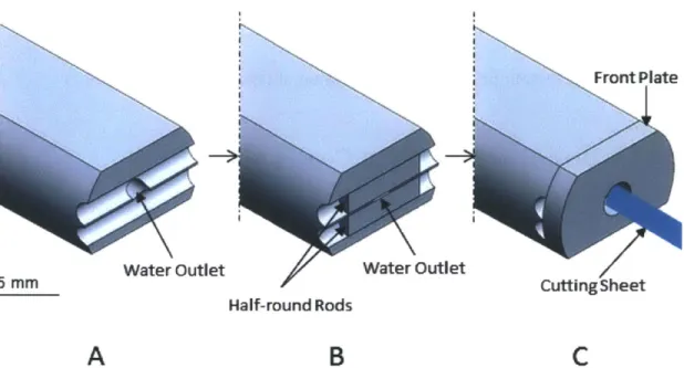
Initial concepts included a cutting jet that impinged on the wound surface at a slight angle in order to remove more material than the existing hydrosurgical device described in section 2.2. One concept, shown in Fig. 3-3, was based on the idea of a plane or chisel shaving away a thin layer of wood. The water would exit from this device in a wide, flat sheet envisioned to peel back a layer of tissue upon contact with the wound surface. This water sheet would be about as deep as a JI jet, for example
50 to 100 pm, and could be as wide as desired. The water sheet would be formed by forcing water through the narrow slit formed by two half-round rods, so shaped
in order to increase the sheet coherence in the narrow dimension. A front retaining plate would hold the half-round rods in place against the outward force of the water pressure.
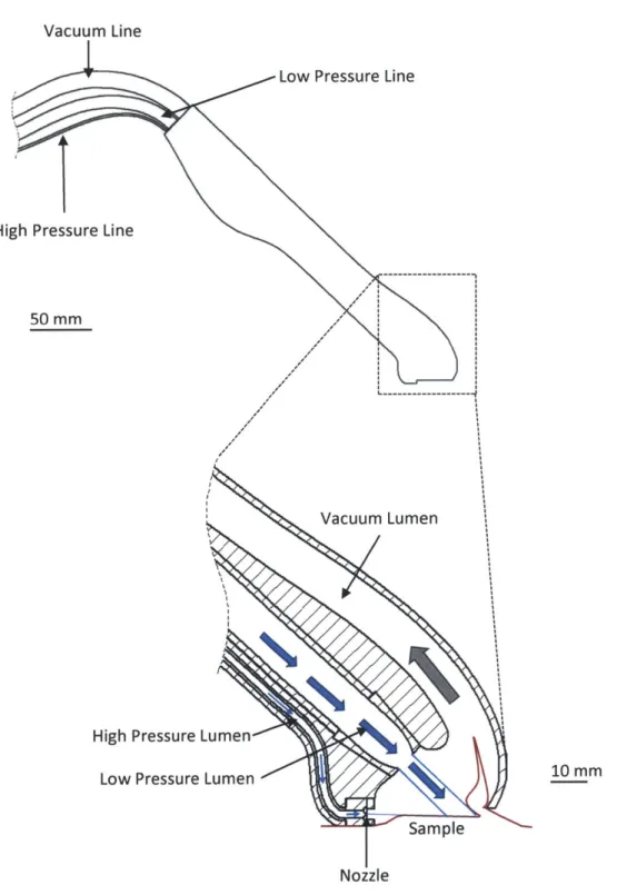
One difficulty in directing a cutting jet to impact tissue would be to control the cutting depth. Without additional measures, the jet would propagate to a depth dependent on the jet and material characteristics, as described in section 2.3. A low-pressure stream of water was added to the water-sheet design in order to limit the cut depth, as depicted in Fig. 3-4. After peeling back the tissue a certain distance, the cutting sheet would intersect the low-velocity stream. Upon intersection, the cutting jet would dissipate into the low-velocity stream and cut no deeper.
This cutting concept was not experimentally tested because it was estimated to
Water Outlet 5 mmR Half-round Rods
A
Water OutletB
CuttingSheetC
Figure 3-3: A conceptual design for generating a fluid sheet about 100 Pm thick. Two half-round rods are held in front of a water outlet by a retaining plate, assembled as shown in the progression A through C. Water forced through these two rods forms the fluid sheet.
have an flow rate greater than the 0.018 L/s limit. A water sheet 100 pm thick and
10 mm wide generated from water pressurized to 15 MPa would have an massive
flow rate of 17 L/s, found by plugging velocity from Eq. 2.4 into the equation for volumetric flow rate:
Q
= AjetUjet, (3.1)where
Q
is the volumetric flow rate, Ajet is the cross-sectional are of the cutting stream, and Ujet is the velocity of the cutting stream, and p is the fluid density.Adding a low-pressure intersecting stream would further increase the flow rate. Since generating a cutting sheet used excessive water, the concept was modified to generate a cutting sheet using one or more discrete nozzles. As depicted in Fig.
3-5, these nozzles swivel back and forth in a plane, together sweeping out a cutting
plane. If ten swiveling nozzles 100 pm in diameter were used to generate the cutting
28
Vacuum Line
Low Pressure Line
High Pressure Line
50 mm
Vacuum Lumen
High Pressure Lumen Low Pressure Lumen
Sample Nozzle
10 mm
Figure 3-4: A device concept that implements the cutting sheet. Suction draws a portion of the tissue upwards, where it intersects the cutting fluid. A portion of the tissue is separated and drawn into the vacuum lumen. A low pressure fluid stream intersects with the cutting fluid, limiting the depth of penetration.
plane with 15 MPa water, the flow rate would be an acceptable 0.013 L/s.
Figure 3-5: The cutting sheet on the left has an unacceptably high flow rate. On the right, a cutting sheet is generated with discrete swiveling nozzles whose jets sweep back and forth in a plane, creating a cutting sheet with a lower flow rate.
The concept efficacy was assessed using a single handheld nozzle, as described in the following sections.
3.2.2 Experimental Setup
Ceramic nozzles supplied by Small Precision Tools [35] were used to test the feasibility of cutting concepts. These nozzles, shown in Fig. 3-6, have been shown effective for the delivery of needle-free injections through the tympanic membrane (ear drum) [36]. Fig. 3-7 shows a simple wand made to interface between the high-pressure hose and the ceramic nozzle. An M8 threaded cap held the nozzles to the wand. An acrylic crush washer, cut from a 1.4 mm acrylic sheet with a laser cutter, created a watertight seal between the wand and the nozzle base. There was a 50 pm gap between the outer diameter of the crush washer and the inner diameter of the mating cap, small enough that any significant expansion of the crush washer under pressure was constrained by the mating cap.
Five nozzle sizes were tested: 50, 75, 100, 200, and 300 pm. Table 3.1 gives the measured maximum pressure that the pump was able to supply to a single nozzle of each size. The pump is able to supply higher pressures to the smaller nozzles. When a clogged nozzle that allowed no water flow was tested, at a pressure of 48 MPa, the
Figure 3-6: A photograph of the type of ceramic nozzle employed, reproduced from
SPT [35].
Figure 3-7: The single nozzle debrider wand. On the right are the acrylic crush washers that created a watertight seal between the ceramic nozzle and the debrider base.
tip of the nozzle fractured.
Table 3.1: Maximum pump pressure for each nozzle tested. Nozzle Dia. (pm) Pump Max Pressure (MPa)
50 Nozzle Fracture at 48
75 40
100 30
200 10
300 2.5
Nozzle Maintenance The ceramic nozzles were prone to clogging. Occasionally the nozzle would fully clog, allowing no liquid to pass through. More frequently the nozzle would partially clog, outputting a diffuse mist. These clogs frequently occurred when the nozzles were unused for a day or more. The nozzles would also clog during use with particles from the thread sealant tape and other sources. Replacing the thread seal tape in upstream fittings with Loctite 545 thread sealant [37] and installing an in-line 10 jim filter reduced clogging during operation.
A clogged nozzle could, in most cases, be cleared and restored to full functionality
using sonication [38] together with VWR Aquasonic Cleaning Solution [39]. Clearing could be enhanced by pre-treatment wit either of two methods: a 50 Pm wire could be threaded through a partially-clogged nozzle and wound around around the nozzle walls, an/or an unclogged nozzle could be used to pressure wash the clogged nozzle.
3.3
Simulating a Sloughy Wound
Slough is a stringy mass of devitalized tissue whose color is indicative of the level of bacterial colonization: white for low colonization and yellow or green for higher bacterial counts [40]. Initial debridement concepts were tested on simulated slough because, as the softer of the two types of necrotic tissue, slough was expected to exhibit cutting behavior more similar to healthy tissue (described in Section 2.3).
The compromised structure of slough was mimicked by degrading the extracellular matrix (ECM) of porcine tissue samples with acetic acid. Healthy skin is structurally supported by the dermal ECM, which is primarily composed of collagen in a char-acteristic triple-helix configuration of three polypeptide chains. Acetic acid is one of the most widely-used solvents for dissolving collagen [41]. Dilute acetic acid causes collagen to swell, unfold, and partly dissolve [42], with exposure to concentrations as low as 0.3% for one hour shown to cause a substantial re-arrangement of intermolec-ular bonds in rat tail tendons [43]. Higher concentrations of acid burn tissue, causing protein to precipitate and form a dry, hard eschar [44]. Acetic acid at concentrations of 50% or higher produced moderate to severe burns on the skin of guinea pigs [45].
To simulate slough, 10% acetic acid was applied to a sample of post mortem porcine abdominal tissue with the epidermis partially removed by scraping. The acid was pooled on the surface of the sample, which was then sealed and incubated for approximately three hours at 25*C. Afterwards, the sealed sample was stored at 4*C and warmed to 25*C at the time of testing. Treatment with acetic acid fixed the tissue, causing the dermis to become stiff and translucent (Fig. 3-8), in contrast to the supple and opaque pre-treated tissue. As the resulting tissue was moist and had experienced the characteristic breakdown in collagen structure, this treatment with acid successfully mimicked important characteristics of sloughy wounds.
3.4
Experimental Testing of Initial Concepts
The purpose of these first tests was to explore cutting concepts and to develop intu-ition for cutting behaviors. The behavior of each nozzle size was tested in sloughy tissue throughout the pressure range the pump was able to supply. Table 3.2 shows the maximum pump pressure tested at each nozzle size, as well as the jet power and flow rate at that pressure.
Any jet directed to impinge on the tissue would inject water into the tissue. With
Dermis-Fat
Muscle
Figure 3-8: A cross-section of tissue after treatment with 10% acetic acid, showing the translucence of the dermis.
Table 3.2: The maximum pump pressure tested for each nozzle size, with the corre-sponding jet power and flow rate. The jet power is calculated using Eq. 2.1 and the flow rate using Eq. 3.1
Nozzle Dia. (llm) Pump Pressure (MPa) Jet Power (W) Flow Rate (mL/min)
50 40 29 33 75 40 50 75 100 30 58 115 200 10 44 266 300 2.5 13 300 34
each reduction in nozzle size, water injection because less evident, due to the nozzle's lower flow rate. The depth of cut created, however, also decreased, as predicted by the decreased jet power.
Jets from the 200 and 300 pm nozzles were difficult to direct; the force on the handpiece from the exiting water was noticeable and interfered with pointing the jet as desired. Furthermore, these larger jets exerted global forces on the sample, propelling the entire sample away from the impinging stream.
By contrast, jets from nozzles with orifices 100 pm or smaller were more easily
controlled: they exerted local forces on the cut area, and they imposed no noticeable force on the handpiece. Example cuts are shown in Fig. 3-9.
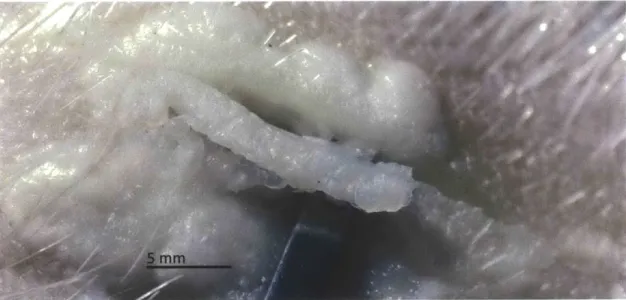
5 mm
Figure 3-9: The water jet sliced the tissue treated with 10% acetic acid, making cuts that were barely visible unless the two edges were spread open to show the cut depth, as in the picture above. The depth of cut increased with jet power.
local forces, injected less water than the 100 pm nozzles, and cut more deeply and clogged less frequently compared to the 50 pm nozzles.
Fig. 3-10 shows the depth of cut created by the 75 pm nozzle as a function of pressure. These cuts were made with the jet directed to impinge on the surface at a 45 degree angle, in order to mimic the expected angle of a debridement jet. When passes were made at 5 MPa, the tissue would whiten and swell with injected water, but no cut was made. Between 10 MPa and 15 MPa, the cut depth increased as a function of pressure. At 15 MPa jet cut completely through the dermal layer, and further increases in pressure did not result in deeper cuts.
3 2.5 k E E E 2 1.5 0.5 0 0 5 10 15
Pressure Applied (MPa)
20
Figure 3-10: Depth of cut made in acid-treated tissue with 75 pm nozzles as a function of pressure. With both 15 and 20 MPa applied, the jet cut through the dermal layer to the underlying fat.
A single angled cut was insufficient to remove material. By making two parallel
cuts, with the second cut angled so that it intersected the first one beneath the surface, it was possible to separate a section of tissue from the sample, see Fig. 3-11. This observation inspired the next generation debridement device, as described in the following chapter.
Figure 3-11: By making two sequential cuts, it was possible to excise section of acid-treated tissue, as shown above.
Chapter 4
Dual Nozzle Cutting Instrument
Two parallel cuts made by a single jet were shown in the previous chapter to be able to excise tissue, albeit in a highly path-dependent manner. This chapter describes a debridement device that includes two cutting jets to accomplish the tissue excision in only one motion. As illustrated Fig. 4-1, the two jets make simultaneous parallel cuts. Because the jets are angled to intersect in the subsurface, their motion excises
a section of the sample.
4.1
Device Description
Designed for flexibility in testing, the dual-nozzle device allows adjustment in the angle and distance between the two nozzles. With the jets intersecting at 1200, the nozzle tips can be set to between zero and 21 mm apart. With the jets intersection at 900, the nozzle tips can be set to between 9 and 30 mm apart. Three example configurations are shown in Fig. 4-2.
The nozzle configuration defines the cross section of the excised strip. If the nozzle tips are in contact with the sample surface during a cut, the width of the strip is equal to the distance between the nozzle tips. Fig. 4-3 shows that changing the angle of the nozzles while maintaining the same distance between the tips determines the depth
/
5 mm
A
5 mm
B
Figure 4-1: Method for excising tissue with two nozzles. In (A), the nozzles each simultaneously make a cut. Because the nozzles are angled towards each other, their cuts separate a section of tissue, which has been removed in (B).
A
B
C
Figure 4-2: The two-nozzle device has adjustable angle and distance between the nozzles, with three example configurations shown. In (A), the nozzle tips are 15 mm apart and directed to intersect at 900. In (B), the nozzle tips are 15 mm apart and directed to intersect at 1200. Finally, in (C), the nozzle tips are 4 mm apart, and they are directed to intersect at 120'.
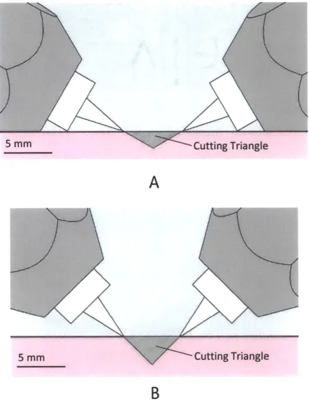
of cut. In each case, the two nozzles remove a strip triangular in cross-section, and hence the action of the two jets can be succinctly described as a cutting V.
5 mm Cutting Triangle
A
5 mm Cutting Triangle
B
Figure 4-3: Cutting cross-section defined by nozzle distance and angle. 1200 and 90' shown.
The base of the device is flat in order to bring the nozzle tips closer to the sample. An external frame, consisting of a base plate and connecting rod, secure the assembly
against the force of the internal high-pressure fluid.
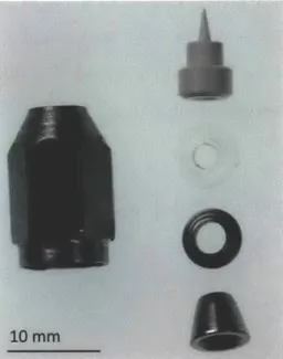
Fig. 4-4 shows a section view of the device. The nozzles are mounted onto 42
stainless steel Yor-Lok elbow fittings referred to as nozzle arms. Sandwiched between the elbow and the nozzle is an acrylic crush washer and a double ferrule, which are made watertight through the compressing action of a threaded cap. The nozzles, ferrules and threaded cap are shown in Fig. 4-5.
I Movable Block I
10 mm Path
Figure 4-4: A cross-section of the cutting device showing the water path.
Each elbow clamps onto a 3.175 mm tube stem, which in turn mounts into a metal block with a 1/8 NPT thread. When the nozzle arms are rotated, this elbow rotates around the tube stem without losing the watertight seal.
One nozzle arm was mounted in a 304 stainless steel block that was rigidly fixed to the frame. The other was mounted in a movable 6061 aluminum block. The moveable block engaged with a lead screw via an extended point set screw. Turning the lead screw caused the movable block to translate and adjusted the distance between the nozzle tips.
con-Figure 4-5: The threaded cap, nozzle ferrules, and acrylic crush washer that mounted the nozzle to the nozzle arm.
nection. The pipe, shown in Fig. 4-6, was threaded into the aluminum block using an M4 thread and sealed with Loctite thread sealant
[37].
A male O-ring created amovable watertight seal between the pipe and the fixed block. Because the aluminum pipe was made of a softer material than the stainless steel fixed block, particulates in the fluid channel would preferentially embed in the pipe and leave a smooth sliding
surface in the fixed-block channel.
A rendering of the two-nozzle handpiece is shown in Fig. 4-7.
10 mm
Figure 4-6: The pipe that allowed fluid communication between the two nozzle blocks, with the O-ring installed.
Knob Water inlet Nozzle arms 10 mm Figure 4-7: Each nozzle is mounted in a nozzle arm that can swivel, thus changing the angle of the jets. The two arms are mounted in separate metal blocks. A knob controls the relative distance between the blocks. By swiveling the nozzle arms and turning the knob, the angle and distance between the nozzles can be adjusted.
4.2
Cutting with Two Nozzles in a Tissue Analog
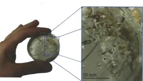
The first tests of the dual-nozzle device were performed using a tissue analog, 10% acrylamide poured into 55 mm petri dishes. The clear acrylamide offers the advantage of making visible the subsurface behavior, and the substance has been employed in studies of needle-free jet injection [30]. A minimum pressure of 2 MPa was required to cut the acrylamide.
In the initial tests, the jets were arranged so that one would cut just behind the other as the nozzles were moved along the sample; they missed intersecting each other by less than a millimeter. The two jets would separate a length of sample with a triangular cross-section. This separated section was visible, however, only by observing the subsurface cutting pattern: the surface adhesion between this section and the remainder of the sample was large enough that the section could not be removed without damaging the sample. Furthermore, the subsurface patterns showed that the cuts penetrated deeper than the triangular section, creating an x-shaped pattern in the sample.
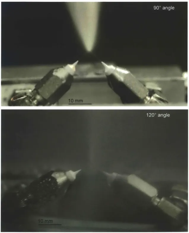
When the jets were arranged to exactly intersect, they dissipated into a fine mist, demonstrating the effect of impinging jet atomization. In impinging jet atomization, two high-energy jets of equal size collide to form a liquid sheet perpendicular to the plane containing the two jets. The jets are entirely dissipated into droplets shed from this sheet, with the exact behavior dependent on the impingement angle, jet velocity, nozzle geometry, and fluid density and surface tension. As shown in Fig. 4-8, when the jets collide at a 900 angle, the mist is directed upwards, in alignment with the vector sum of the momentum from the two jets. When the jets collide at 1200, the mist is more diffuse, which correlates to the momentum from the two colliding jets largely canceling each other out. If the two jets collided at 180*, their momentum would exactly cancel, and the mist would not move preferentially in any direction, instead forming a circular liquid sheet [46].
The process of atomization dispelled much of the energy of the cutting jets. In
Figure 4-8: Atomization created by impinging jets. The shape of the mist plume corresponds to the net momentum of the mist after the jets collide. The jets inter-secting at 900 have a net upward momentum, directing the plume vertically. The jets intersecting at 1200 have smaller net vertical momentum, resulting in a more diffuse plume.
one study, three atomizers were shown to dissipate between 85% and 98% of the input energy into thermal energy [47]. For this reason, cuts made in the acrylamide with the impinging jets no longer penetrated deeper than desired. The mist created at the jet intersection did not retain enough energy to cut. Each jet formed an edge of a
cutting triangle that terminated at the jet intersection.
With the cut surfaces lubricated by water from the mist, the excised sections were either cleared during treatment, as in Fig. 4-9, or were easily removed with thumb forceps afterward.
Figure 4-9: A v-shaped cut that penetrated no deeper than the jet intersection, made with 75 pm nozzles spaced 5 mm apart with jets intersecting at 1200.
The limited depth of cut with the impinging jet configuration gave the operator the ability to carve out arbitrary shapes in the acrylamide. The trough shown in Fig. 4-10 was enlarged bit by bit by engaging just the tip of the cutting triangle during each motion. For these cuts, 50 pm nozzles were arranged to intersect at 90', and the nozzle tips were 10 mm apart. Although it was possible to carve out a general bowl shape, the sides of the bowl were jagged, a relic of the steep intersection angle of the cutting jets.
The top layer of acrylamide could be removed by making a series of side-by-side cuts. The appearance of the resulting surface was dependent on the jet intersection angle used when making the cuts, shown for three configurations in Fig. 4-11. In each configuration, the parallel cuts result in a series peaks and valleys with the peak rising 2 mm above the valley. For the shallowest intersection angle of 850, the peaks
Figure 4-10: A rough surface created in many motions by two jets intersecting at 90' intersection and created by 50 lrm nozzles spaced 10 mm apart.
and valleys rise and fall steeply, with only a 2 mm spacing between peaks. For an intersection angle of 1100, the slope is more gradual, and the peaks are spaced every 4 mm. By widening the intersection angle to 130' and making extra smoothing passes, the distance between the peaks was extended to 8 mm. Testing would be required in order to assess the effect of an uneven surfaces such as these on wound healing.
In summary, the two-nozzle technique permitted both controlled cutting in a tissue analogue; the result was a textured surface whose shape depended on nozzle position and angle.
4.3
Cutting Necrotic Tissue
In the previous section, testing of the two-nozzle device in acrylamide showed the importance of aligning the jets to impinge. This section describes the behavior of these impinging jets in cutting necrotic tissue, both hard eschar and moist slough.
85* Intersection 10 mm 110* Intersection 10 mm 130* Intersection 10 mm
Figure 4-11: Acrylamide testing, 2 MPa jet pressure. A: 850 intersection, tips 10 mm apart. 2 mm between peaks, 2 mm depth. B: 1100 intersection, tips 6 mm apart. 4 mm between peaks, 2 mm depth. C: 1300 intersection, tips 5 mm apart. 8 mm between peaks, 2 mm depth. 51
4.3.1
Simulating and Cutting Hard Eschar
Hard eschar is a scab of dry devitalized tissue, frequently present on the heals of patients with restricted blood flow. The mass may be removed surgically or softened with moist dressings for manual removal [40], but other existing debridement devices such as the VersajetT M are unable to remove hard eschar [20].
In order to assess the feasibility of using the two-nozzle device debride eschar, it was necessary to simulate this wound material. Two methods found in the literature were tested. The first method was to scorch the surface of the sample with a butane torch. This method was based on a technique that uses diathermy to simulate eschar on porcine tissue for the purpose of training surgeons [48]. In practice, the butane torch caused carbonization on the surface of the sample, but the sample underneath the carbonization was rubbery, not hard like eschar. This method of simulating eschar was thus rejected.
The second method involved the use of dried dermal tissue as simulated eschar [49]. Four types of samples were dried, shown in Fig. 4-12: untreated porcine tissue, porcine tissue with the epidermis partially scraped away, acid-treated tissue, and a sample of the scorched tissue, as well as a scorched sample already subjected to the debridement jets. After seven days of exposure to air in a fume hood, only the uncut scorched sample was fully desiccated; the drying process had been accelerated due to the moisture removed during scorching. The sample with the intact epidermis was protected from desiccation on all but the edges, and the remaining samples had pockets of moist tissue. The fully desiccated sample was selected as the best eschar approximation.
More energy was required to cut this hard material, and so the nozzles were held at the sample surface, the tip distance was reduced to 2 mm, and the cutting pressure was raised to 15 MPa. This pressure was the same pressure that had made the deepest cuts in sloughy tissue, see Fig. 3-10. The jets were set to intersect at 1200 because shallower intersection angles had given smoother surfaces in acrylamide.
Figure 4-12: Four types of samples were dried in order to simulate hard eschar. Clock-wise from left: sample scorched by butane torch, sample treated with acid, sample scorched with butane torch and carbonization rinsed away, sample with epidermis scraped away, and sample with epidermis intact.
Before cutting the sample, the mist created by the impinging jets acted as a lavage and washed away the external carbonization, revealing a deep red surface, shown in Fig. 4-13. Lowering the cutting triangle into the sample, the jets were able to penetrate. No water was injected into this fully-desiccated sample; instead, the water from the jets was reflected at the cut bottom and exited the site in a low-pressure stream. This stream, when reflected vertically, attained a height of about 30 mm.
Because the sample was rigid and did not swell with injected water, it was possible to make cuts with precise control. The second panel of Fig. 4-13 shows a single cut that was made, successfully excising part of the sample. Following that initial cut, the remainder of the sample was debrided in a single continuous operation involving a series of passes. Because the debrided area was a white color and because of the control given with this rigid sample, it was possible to both know where cuts needed to be made and to execute them accurately.
10 mm
A
B
Figure 4-13: The scorched and dried sample (A) before treatment, (B) after lavage and a single cut (traced in yellow dots), and (C) after full debridement.
leaving softened layer underneath. The softened layer could be removed with a curette. Attempting to remove a second layer of material with the jets was suc-cessful, though less precise without the advantage of a color change marking the debrided area. Because eschar in chronic wounds is composed of a hardened layer that covers soft tissue, any cuts made with this device that penetrated into the soft tissue layer would inject water into the tissue. To avoid this possibility, the suggested method for using this device in eschar would be to remove the bulk of the eschar with the cutting jets, and then curette the remainder of the softened eschar before the jets penetrate deeply enough to inject water into the underlying tissue. The jets rehydrate the underlying dry tissue, similar to the action of moist dressings. This proposed method could potentially be a time-saving alternative to applying moist dressings, but verification from further tests on samples that include both eschar and soft tissue components will be necessary.
4.3.2
Cutting Sloughy Wounds
As described in Section 3.3, sloughy wounds can be simulated using acetic acid. A pressure of 15 MPa was again used to cut, though the jets cut more deeply in the softer material compared to hard eschar. For this reason, the distance between nozzle tips was increased to 4 mm while the intersection angle was maintained at 1200 in order to produce the smoothest surface possible. Again, the nozzle tips were held directly at the tissue surface.
If cuts were made with the nozzle tips closer than 4 mm, the excess energy of the cutting jets would inject water into the dermis adjacent to the cut, causing it to pucker and turn white, as shown in Fig. 4-14. If cuts were made with the nozzle tips spaced at 6 mm, the jets would not cut deep enough to intersect.
Assessing Cut Width and Depth The dimensions of cuts made in sloughy tissue were measured from a 3D model made of the sample surface. To construct this model,
Figure 4-14: With the nozzle tips too narrow, white puckering was observed along the cut. Circled in photo: 15 MPa applied to nozzles with tips 3 mm apart, 75 pm nozzles.
a series of between seven and twenty images were taken of the sample, each image showing from a different angle the cut and an adjacent set of calipers. Before taking photos, the cut and sample were speckled with black spray paint in order to increase the fidelity of the 3D rendering. Software generated a 3D model from these images
[50]. Three sets of points of at least fifty points each were manually picked in this
model, two sets marking the cut edges and one marking the deepest part of the cut
[51]. These points were analyzed in MATLAB to give cut width and depth [52]. These
cut dimensions were validated by comparing them to caliper measurements, see Fig. 4-15. This modeling process is shown pictorially in Fig. 4-16.
A tissue sample in which five cuts were made is shown in Fig. 4-17. These cuts
have no whitening or puckering, showing that the jets no longer carry excess energy and water is not injected along the cut edges. The cuts made in soft tissue maintain a discernable V-shape, similar to the cutting behavior in acrylamide. The graph at the bottom of Fig. 4-17 gives the cut dimensions made by measuring the width at the top of the V, and the depth from the sample surface to the deepest point of the cut, as discussed above. The graph gives measurements along the length of the cut, following the translation of the cutting V. The average width and depth for .each of these five cuts with the standard deviations are shown in Fig. 4-18.
Although there was no whitening at the surface layer and the jets cut no deeper than the intersection point, swelling indicated that water was injected deeper into the sample. This swelling in one part of the sample caused a bulge that visibly distorted the one of the cut dimensions. The cut marked Cut 1 in Fig. 4-17 grows wider as it passes over the area most swollen by deep water injection. At the sample center, Cut
3 was made first. The injected water from the adjacent cuts on either side swelled the
tissue and pushed the sides of Cut 3 inwards, making the cut appear narrower and deeper. In future testing, measurements were taken after each cut in order to avoid such distortions. Because water injection caused the shape of the tissue during cuts, it was not possible to control the cut path well enough to make side-by-side cuts.
El K x xx 4 X >0< xx x x PickedPoints/MATLAB Processed 0 Measurenents by Hand ' ' ' ' 0 5 10 15 Length I I 5 10 15 Length 20 Along Cut 25 (mm) El *Ix
I
30 35 40 x x X xx xx x > x XI
I I - - - I I 20 Along 25 Cut (mm) 30 35 40Figure 4-15: Measurements of the cut made with calipers and showed adequate correlation to validate the measurements taken
from the 3D image from the 3D model.
58 5 4.5 4 -3.5 F 3 F
.- -6
E E3 2.5 2 -1.5 F 1 F 0.5 F n 3 x x K K 2.5 2 1.5 1 1-E E-0L ~xE x 4 x x Sx 0O
0.5 F 0' 0A
B
Side 1 Depth Side 2
Figure 4-16: To construct 3D images of the cut surface, a series of photos of the cut
(A) was uploaded to Autodesk 123D Catch. The STL file from Autodesk's rendering
(B) was imported into Meshlab (C), where points were manually designated to mark the cut edges and depth (D). These points were analyzed in MATLAB to find cut width and depth.
9 8 7 E 4 o3 1 0' 0 E3 E 6-o Q U 10 IC 20
Length Along Cut (mm)
20
Length Along Cut (mm)
30 40
30 40
Figure 4-17: Cuts made in tissue treated with 10% acetic acid using 15 MPa and nozzles 4 mm apart intersecting at 1200. The colored arrows in the photograph show which cut is plotted in the graph showing cut dimensions, and blue dots trace each cut. 60 AOW~ I. I - -I
'4
2F I4 mm alone _ -Cut Depth Cut Width
I-
F-I F-I -2 Cut Assessed 3 (Designated 4 Number) 5Figure 4-18: The average width and depth for the five cuts bars indicate the standard deviation for each cut.
shown in Fig. 4-17. The
8 7 6 1115 -E ~4-:2 3-2 1 0 1
In Fig. 4-17, the depth of cut appears to vary with a higher frequency around a slowly changing average depth of cut. Contributing factors to these higher frequency variations include hand tremor, tissue variability, and imprecision in visually keeping the nozzle tips at the surface.
None of the five cuts shown was successful in completely excising the tissue. In each case, the jets failed to cut though either at the start or end of the pass, and in three cases there was at least one uncut strand of tissue midway along the pass. In order to take cut measurements, the separated piece was removed with thumb forceps. This chapter showed that impinging jets are able to remove portions of necrotic tissue. The following chapter will detail additional tests and changes made to optimize the device performance.
Chapter 5
Optimizing Design for Cutting
Necrotic Tissue
In the previous chapter, a dual-nozzle device with intersecting cutting jets was shown to be capable of excising discrete sections from eschar and sloughy wounds. To be considered a success in cutting sloughy wounds, however, many of the behaviors demonstrated in the eschar would need to be replicated: sections of the sample would need to be excised without damage to the adjacent tissue, and excised with enough control to remove a tissue layer via side-by-side cuts. In addition, a fully realized device would need to locally evacuate waste in order to prevent cross-contamination, and it would need to be demonstrated that the device did not propagate bacteria into the wound. Table 5.1 gives a summary of the configurations and methods that will be described in this chapter, and the effectiveness of each in accomplishing these goals.
Table 5.1: A summary of device performance with different cutting methods. A mark of '+' denotes satisfactory performance, a mark of '0' denotes inconsistent performance, a mark of '-' denotes an unmet criterion, and 'ND' denotes a criterion that was not determined. Except for the sample type labeled eschar, all tests were performed using simulated slough. The distance given in the description of each configuration refers to the distance between the cutting nozzles. Cuts made with the nozzles 4 mm apart had a jet intersection angle of 120*, and the tests performed at 2 mm apart had a jet intersection angle of 1100. Eschar, 2mm 4 mm 4 mm, vac 4 mm, vac, fast 2 mm 2 mm, pre-cut 2 mm, pre-cut, vac No visible unwanted damage + + 0 0 + + 0 Side-by-side cuts + -+ Min cutting pressure (MPa) 15 15 15 15 10 7 6 Waste contained and evacuated -+ + -+ Bacteria not driven in ND ND ND ND ND + +