Publisher’s version / Version de l'éditeur:
Vous avez des questions? Nous pouvons vous aider. Pour communiquer directement avec un auteur, consultez la première page de la revue dans laquelle son article a été publié afin de trouver ses coordonnées. Si vous n’arrivez pas à les repérer, communiquez avec nous à PublicationsArchive-ArchivesPublications@nrc-cnrc.gc.ca.
Questions? Contact the NRC Publications Archive team at
PublicationsArchive-ArchivesPublications@nrc-cnrc.gc.ca. If you wish to email the authors directly, please see the first page of the publication for their contact information.
https://publications-cnrc.canada.ca/fra/droits
L’accès à ce site Web et l’utilisation de son contenu sont assujettis aux conditions présentées dans le site LISEZ CES CONDITIONS ATTENTIVEMENT AVANT D’UTILISER CE SITE WEB.
Internal Report (National Research Council of Canada. Institute for Research in
Construction), 1995-05
READ THESE TERMS AND CONDITIONS CAREFULLY BEFORE USING THIS WEBSITE. https://nrc-publications.canada.ca/eng/copyright
NRC Publications Archive Record / Notice des Archives des publications du CNRC : https://nrc-publications.canada.ca/eng/view/object/?id=c35c88cc-ec32-462f-8ef6-a930209a4606 https://publications-cnrc.canada.ca/fra/voir/objet/?id=c35c88cc-ec32-462f-8ef6-a930209a4606
NRC Publications Archive
Archives des publications du CNRC
For the publisher’s version, please access the DOI link below./ Pour consulter la version de l’éditeur, utilisez le lien DOI ci-dessous.
https://doi.org/10.4224/20375279
Access and use of this website and the material on it are subject to the Terms and Conditions set forth at
Application of Lab Procedures for the Dynamic Evaluation of Roofing
Systems. Part 1: Review of Existing Standards
I
f f y d /
Institute for lnstitut de10-
692
Research in Construction recherche enW L Y Z
1,
r? constructionApplication of Lab Procedures for the
Dynamic Evaluation of Roofing Systems
.,. . ,. *, .\ . .. . ,.Part 1: Review of Existing Standards
... .i, ::> I .I, ! ,I: 1::::
$;~T
ip,lI::?<::: ,'i::::P,lf:i!i::,:1 r:::i:::: i:;:*
r:
:.ie;,
: , (,
; C1.7 .... i'i,:: ,... ,::jt:::, . . I .i<_!
by Dr. A. Baskaran and Dr.
0.
Dutt
Internal
Report No.
692
Date of issue: May 1995
This Is
an
Internal report of the lnstitute for Research in Construction. Although not Intended for general dlstrlbution, it may be cited as a reference in other publications.APPLICATION OF LAB PROCEDURES FOR THE DYNAMIC
EVALUATION OF ROOFING SYSTEMS
PART 1: REVIEW OF EXISTING STANDARDS
By
4
Drs. A. Baskaran and
0.
Dutt
May 1995
Application of Lab Procedures
-
Existing Standards PagcdlABSTRACT
w i n d induced effects on roofing systems are dynamic because of the wind's variations with respect to
time and space. Experiments were conducted at NRCNRC on roofinp
materials
.
The data reported in "Evaluation of Roof Fasteners Under Dynamic Wind Loading-
Baskran and Dutt (1995)'; clearly indicated that the fastener failure load and mode differ significantly under dynamic testing as compared tostatic testing. To develop a lab evaluation protocol for the
roofina,
existing test procedures were systematically reviewed. The review includes: the standard lab test methods currently being practiced inNorth America, such as the Factory Mutual (FM 4470) and Underwriters Lab (UL 580) procedures as well
several international test procedures used by the roofing community. It has been concluded that the
existing North American test methods are insufficient for evaluating roofing systems since they do not
consider the effects of dynamic wind loading. In Europe, fatigue has been acknowledged as an important
factor in the evaluation of mechanically attached roofing systems. Thus the European test methods are
more realistic than those adopted in North America.
ACKNOWLEDGMENT: Part of this research work has been jointly sponsored by IRCINRC and the
Department of National Defence (DND). Contribution of Mr. S. Nagy, DND is greatly appreciated.
TABLE OF CONTENTS
ABSTRACT 2
CHAPTER 1 INTRODUCTION ON DYNAMIC EVALUATION 5
1 .I DYNAMIC PROCESS
1.2 NEED FOR DYNAMIC EVALUATION 1.3 SCOPE OF THE REPORT
CHAPTER 2 REVIEW OF EXISTING STANDARDS 10
2.1 NORTH AMERICAN APPROVAL TEST METHODS 10
2.1
. I
FACTORY MUTUAL (FM) 4470-UPLIFT PRESSURE TEST 102.1.2 UNDERWRITERS LABORATORIES (UL) PROCEDURE 580 TEST 12 2.1.3 AMERICAN SOCIETY FOR TESTING AND MATERIALS (ASTM) D 1761 TEST 12 2.1.4 OTHER RELATED STUDIES ON ROOF TESTING 14 2.1.5 LIMITATIONS OF NORTH AMERICAN TEST METHODS 14
2.2 EUROPEAN APPROVAL TEST METHODS 15
2.2.1 UEATC-STANDARD WIND UPLIFT TEST PROCEDURE 15 2.2.2 BRERWULF
-
BRITISH RESEARCH ESTABLISHMENT REAL TIME WlNDUNIFORM LOAD FOLLOWER 17
2.2.3 NT BUILD 307
-
STANDARD WIND LOAD RESISTANCE 19CHAPTER 3 CONCLUDING REMARKS 22
3.1 SUMMARY
3.2 PROPOSED EVALUATION PROCEDURE
CHAPTER4 REFERENCES 24
LlST OF FIGURES
Figure 1 Effect of building height on wind-induced pressure fluctuations (Baskaran. 1986) 6
Figure 2 a) Pressure variations on the walls of a building (Dalgliesh. 1970) 8
b) Pressure variations on the building roof (Baskaran and Kashef, 1995) 9
Figure 3 FM 4470 Test Apparatus (FM Research, 1992)
I 1
Figure 4 Failure of a Batten Attached System after FM Testing (FM Research, 1992) 12
Figure 5 UL Test Apparatus (Haddock, 1992) 13
Figure 6 a) Accumulated Probability Distribution for Wind Load Cycle 16
b) Wind Load Cycle (5 year return period) 16
c) UEATc Wind Load Test Cycle (Gerhardt, 1990) 16
Figure 7 BRERWULF system response on a roof specimen (Cooke et al., 1988) 18
Figure 8 NT BUILD 307 Test Apparatus
20
Figure 9 a) NT BUILD 307- Dynamic Load Cycle 21
b) NT BUILD 307
-
Static Plus Dynamic Load 21Figure 10 NT BUILD 307 Dynamic Load, Fixed Intensity Load Pattern 21
Figure 11 Simplified representation of wind pressure used for testing 23
LlST OF TABLES
Table 1 Loading Cycle for UL 580 13
CHAPTER 1
INTRODUCTION ON DYNAMIC EVALUATION
1.1 DYNAMIC PROCESS
Building envelopes are designed to separate the controlled indoor environment from the uncontrolled outdoor environmerti. The building envelope consists of such assemblies as the wall, roof, window and basement. Each assembly has its unique performance requirements and functions. The outdoor environment involves several parameters which may act as dynamic driving potential. These include:
.
wind.
rainlsnow.
temperature.
solar radiation.
earth rnovenents.
noise.Driving potentials may act independently or combined; for example, wind-driven rain conditions. Their intensity depends on the geographical location and seasonal conditions. The designer has to select and design the envelope to withstand these driving forces. All of the driving potentials listed above are dynamic in nature. For example, consider the wind-induced pressures on a building roof that depend on parameters such as:
.
wind speed and turbulence intensity.
wind direction and flow stability.
building topography.
building geometly.
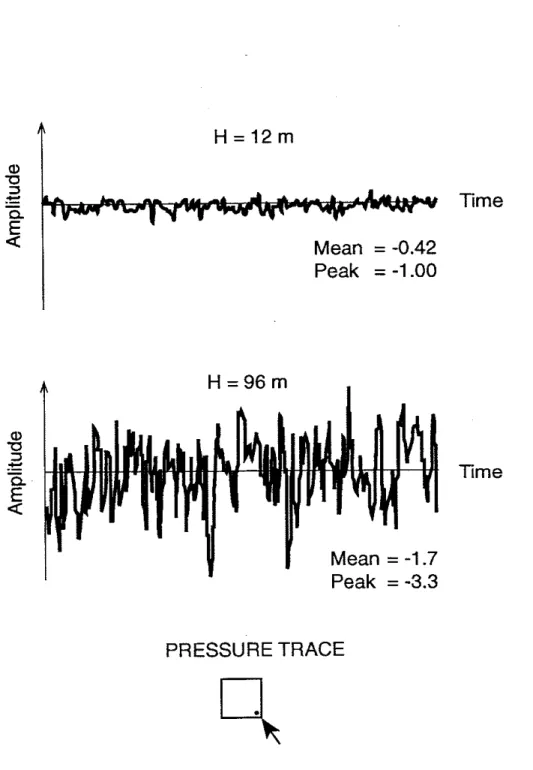
architectural features such as exposed mullions and parapetsFigure 1 from a study carried out by Baskaran (1 986) illustrates the effect of one such parameter building height on the pressure coefficient. Roof pressure traces measured in the wind tunnel are shown for two buildings with the same cross sectional area but of different height. One building is 12 m high considered to be low building and the other building is 96 m high representing a tall building. Pressure fluctuation varying with respect to time is shown in the figure. The random pressure fluctuations are higher in the case of the taller building.
w
u
3.-
Time
Mean
= -0.42
Peak
= -1.00
a,Y
C .--
Time
Mean = -1.7
I 8Peak
=
-3.3
PRESSURE TRACE
h
Figure 1 - Effect of building height on wind-induced pressure fluctuations (Baskaran, 1986)
In addition, the wind-induced pressure on the same building differs on the different buiiding envelope. This is illustrated in Figure 2 (a) and (b). Figure 2 (a) presents the pressure fluctuations on the faces of a building, namely windward wall, leeward or back wall and side wall. It is clear from the figure that the wind induces, mostly positive, fluctuations (pressures) on the windward wall and creates suction (negative) fluctuations on the leeward and side walls. This is mainly because when wind flows around the building it creates different type of flow pattern on different sides of the building. In this case, wind blows perpendicular :o the building and forms stagnation on the windward side. It starts separating from the windward wall edges and thus the side faces of the building are in the separated region.
Recirculations are developed at the back side of the building creating low intensity suction forces. Figure 2 (b) represents typical mean roof pressure coefficients measured in the wind tunnel. The data is for a square plan building exposed to oblique wind direction. It is evident from the figure that an imaginary line of symmetry exists along the diagonal of the roof. The pressure coefficients are maximum near the two leading edges. They decrease as one moves away towards the leeward edge. For this roof configuration a zero pressure coeEicient represents occurrence of flow reattachment. After reattachment, the
coefficients are positive.
What is clear from the Figures 1 and 2 is that the wind effects on buildings vary with respect to time as well as location (space). In other words the wind flow conditions around buildings and the wind-induced effects on the buildings have dynamic characteristics. Similar arguments can also apply for other driving forces that act on the roof. Processes of this nature are called "dynamic process" so that the roofing system has to be evaluated in laboratories by simulating simultaneously all or most of the forces.
1.2 NEED FOR DYNAMIC EVALUATION
Wind tunnel testing of tall building models to quantify the wind induced effects are no longer uncommon in the design stages of buildings. However, the performance prediction of the individual assemblies such as roofing systems cannot bs identified by means of wind
-
tunnel testing alone: testing full scale roofing systems in the simulated dynamic environment is required. This dynamic evaluation provides many benefits, of which a few are discussed below:.
realistic fastener loads to prevent backout or pullout due to excessive fastener loading; load distribution on the roof Mth various deck types;fatigue behavior of fasteners, deck and attachment systems; effect of temperature variations on the membrane strength;
Application of
Lab
Procedures-
histing Standards Pagw7information about the performance of the design and potential disclosure of design and fabrication weaknesses and suggest improvements;
air leakage rate of the tested roofing system;
structural adequacy of the assemblies and anticipated deflection at the joints and other required locations:
joint and seal performance for water tightness;
effectiveness of the thermal breaks and thermal insulation;
.
official evidence and certification of the adapted design.Windward wall ( I ) 2 -- Leeward Wall -2 4 2 Side Wall Time, t
Figure 2 (a) Pressure variations on the walls of a building (Dalglesh, 1970)
Figure 2
(b)
Pressure variations on a building roof (Baskaran and Kashef, 1995)1.3 SCOPE OF THE REPORT
This report presents an overview of the standard test methods currently being used for approval in North America
and
Europe. In addition, the limitations of these test methods are presented based oninformation collected from related studies.
CHAPTER 2
REVIEW OF EXISTING STANDARDS
2.1 NORTH AMERICAN APPROVAL TEST METHODS
At present in North America there are two test methods being used for approval testing of mechanically attached roof systems. They are the Factory Mutual (FM) 4470 and the Underwriiers Laboratory (UL) 580 procedure. Both are described in the following section. In addition, ASTM D 1761 -Test Methods for Mechanical Fasteners in Wood
-
is also reviewed.2.1.1 FACTORY MUTUAL (FM) 4470
-
UPLIFT PRESSURE TESTThe FM Uplift pressure apparatus is 9 ft long by 5 ft wide (2.7 x 1.5 m) steel frame. The test panel components that have been assembled according to the manufacturer's specifications are placed on the frame. Metal angles are attached around the assembly's perimeter. The attachment is then secured with C-clamps along the perimeter (ref.: fig. 3). Recently, the FM 4470 test method has been revised to test samples measuring 24 ft long by 12 ft wide (7.3 x 3.8 m). FM has determined that a larger size yields more accurate and realistic results (FM Research 1992). The pressure is supplied through positive air pressure to the bottom of the roof panel using an air compressor. The initial test pressure is 30 psf (1.4 kPa) and maintained for one minute. The pressure is then increased by 15 psf (0.7 kPa) each
successive minute until failure is noted in the test panel.
The scope of FM 4470 is to designate an 1-60 or 1-90 windstorm classification to the roof assembly tested. ("I" indicates that the assembly has passed other FM tests related to fire, hail, leakage, corrosion and foot traffic.). To obtain a factory mutual I roof cover approval, the test assembly must withstand certain pressure level for one minute duration. For example, to obtain an 1-90 Classification, the test assembly must resist 90 psf (4.2 kPa) for one minute. Similarly, for I
-
60 classification, a pressure of 60 psf is applied for a one minute duration. Figures 3 and 4 respectively illustrate a batten attached roof system during testing and the resulting fastener pull-out after the test.FM Loss Prevention Data Sheet 1-28s enables wind speeds to be related to wind velocity pressures. A velocity pressure is deduced based on knowledge of surrounding ground condiiions, building height and basic wind speeds in that area. There are three FM zones characterized by different wind velocity pressure ranges and the class of roof cover to be used is based on the relevant zone category determined from the wind pressure.
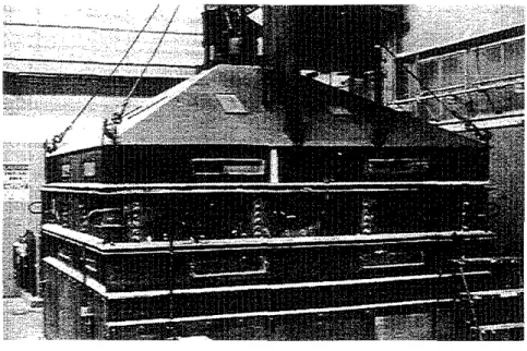
Figure 3 FM 4470 Test Apparatus (FM Research, 1992)
Figure 4 Failure of a Batten Attached System after FM Testing (FM Research, 1992)
2.1.2 UNDERWRITERS LABORATORIES (UL) PROCEDURE 580 TEST METHOD
The UL 580 testing apparatus, illustrated in Figure 5, is a minimum of 10 by 10 f i (3 x 3 m). It is composed of a vacuum chamber, test frame and a pressure chamber. They are positioned on the top, middle and bottom section respectively. The test assembly is built as specified by the manufacture installation procedure and positioned in the test frame which is 381 mrn deep. The vacuum chamber applies steady and oscillating negative pressures to the top of the assembly while the pressure chamber applies steady posifive pressures to the underside.
The positive and negative pressures are applied at values and time duration's given in Table 1. The UL 580 designation classifications are: UL
-
15, UL-
30, UL-
60 and UL-
90. The testing period is 80 minute divided into 5 phases. Phase 3 is 60 minute duration's and the remainhg phases are 5 ninutes each. Negative pressure is applied throughout the entire phase while positive pressure is applied during phase 2, 3 and 5. Oscillating pressure is only applied in phase 3 at a frequency of about 10 second per cycles. A UL-
15 rating is achieved if the roof assembly remains intact followmg the completion of all phases under class 15 loading cycle. If the assembly surpasses class 30, 60 and 90 loading cycle, then the assembly is designated as UL-
30, 60 or 90 respectively.2.1.3 AMERICAN SOCIETY OF TESTING AND MATERIALS
-
D 1761At present there is only one North American standard test method for the evaluation of mechanical fastener withdrawal. This method is part of ASTM D 1761, Test Methods for Mechanical Fasteners in Wood
D
1761 includes 5 separate tests and sections 1 to 11 describe the method for withdrawal testing.The purpose of the test is to determine the maximum load required to wifhdraw a fastener from the wood. The wood used should be of representative density and free of growth defects. Fasteners are installed to a penetration depth of 32 mm (1.25 ") in the wood. A loading apparatus such as an lnstron is then used to apply a tensile load at a withdrawal speed of 2.54 mmlmin (O.lO"/min) and the maximum load attained during the testing is recorded. ASTM D 1761 test method may be useful in the testing of fasteners for certain applications where the withdrawal speed expected is suitably matched to that of the test method. However, since withdrawal speed is a critical factor in determining pullout resistance, the intended use of the fastener should be carefully considered and, if necessary, the withdrawal speed should be altered.
Application of Lab Procedures
-
Existing Standards PagdlzFigure 5 UL Test Apparatus (Haddock, 1992)
Negabve Pra- Posltlve Pressurn
Time
Test Dmbon. Pounds Per Inches of Wster Pounds Per Inches of Water
Phase Minutes Square Foot (kPe) (-1 Square Foot (kPa) (mml
Qasa 15
I
Class 60I
Qass 90Table 1 Loading Cycle for UL 580
Because the fluctuating nature of wind loading the fastener may be subjected to a more abrupt load than that applied by a pulling rate of 2.54 mrdmin. Using a constant separation speed should not be
appropriate in the evaluation of fasteners for roofing applications.
2.1.4 OTHER RELATED STUDIES FOR ROOF TESTING
In Australia, Byrne (1976), Morgan and Beck (1977), Mahendran (1990 a, b) and Mahendran (1994) used an experimental setup to apply dynamic loading on sheet-metal roofing. Warshaw and Hoher (1985) conducted dynamic testing on 10
-
by 10 foot panels of mechanically attached roof membranes. The simulation consisted of applying pulsating pressures to the panels and increasing the value by specified increments. Results showed that failure occurred at 50 percent of the static pullout specified bymanufacturers. There are other factors not considered by the current test methods. For an example, fatigue, caused by wind flutter can significantly reduce failure loads and should be accounted for in the evaluation of roof systems. Studies conducted by Ellifritt and Burnette (1990) investigated the effects of dynamic wind loading on the pull-over strength of fasteners. Dynamic loading was induced by applying cyclic loading on the adjacent purlin. Before failure of the connection occurred, the number of cycles was recorded and used to analyze different fastener configurations.
There are other factors not considered by the current test methods. For instance, existing test methods do not account for the effects of positive pressure from the building's interior (Bieber 1990). A study by Zargharnee (1 990) considered the effect of pressures below membranes. His study investigated failure mechanisms of mechanically attached systems that account for air infiltration underneath the membrane. Another necessary modification to current methods would be the use of larger test assemblies to reduce the edge effect (Hasan and Ammerman 1992). A study by Schroter (1985) also expressed concerns
about the effect of perimeter attachments. Schroter's study attempted to evaluate the effects of sheet metal distoltion, another factor not considered in present test methods.
2.1.5 LIMITATIONS OF NORTH AMERICAN TEST METHODS
Studies indicate that the FM 4470 and UL 580 testing procedures are inadequate to evaluate the wind induced fatigue effects on the mechanically attached roofing systems. FM statistics showed that during the period of 1960-1990.21 windstorms occurred. Damages incurred on FM rated mechanically attacned roofs totaled 14 million dollars (Hasan and Ammerman 1992). Following Hurricane Hugo, it was noted that 1-90 rated roofs that should have sustained 150 mile per hour winds failed at winds of 40 to 60 miles per hour (Bieber 1990). In addii ion, standing seam metal roofs rated according to UL 580 failed at wird loads and wind speeds 20 to 60 percent of the expected capacity (Decker 1989). Most manufacturers
have attempted to equate ratings to wind speeds but this assumption fails. UL has acknowledged this and warned that "the 580 procedure does not demonstrate that a system can resist any spec if^ load or wind velxity (Schroter 1992). Experts agree that the present test methods lack the ability to simulate field coditions realistically and improvements are needed. The major flaw associated with FM 4470 and UL 580 is their lack of dynamic testing as both are static and do not simulate the effect of wind
fluctuations. Fatigue caused by wind flutter can significantly reduce failure loads and should
be
accounted for in the evaluation of roof systems. The ASTM method, being a static load test, is not appropriate for the evaluation of fastener pull-out in mechanically attached roofing. A fastener fixed through the membrane and insulation layer to a wood deck is subjected to a considerable amount of dynamic loading that can cause fatigue in the wood surrounding the fastener, resulting in a significant reduction of pull-out load.
2.2 EUROPEAN APPROVAL TEST METHODS
In Europe, fatigue has been acknowledged as an important factor in the evaluation of mechanically attached roof systems. The theory behind dynamic testing is more accepted and advanced than in North America and consequently test methods are more realistic (O'Dea 1990). Thus, the European test methods are more realistic than those adopted in North America. Problems associated with fasteners applied
too
close to the edge are controlled by use of larger test specimens and correction factors(Gerhardt and Gebatsch 1991). Best of all, the effects of dynamic loading are simulated, thus yielding realistic results. However, drawbacks associated with sheet distortion, perimeter, and seal attachments that structurally reinforce test units, may still be a problem according to Schroter (1985). Three different approaches, being used to perform dynamic testing, are described in the following section.
2.2.1 UEATC-STANDARD WIND UPLIFT TEST PROCEDURE
The UEATc
-
(European Technical Construction Agreement) Standard Wind Uplii Test Procedure is being prepared based on a procedure developed by Gerhardt and Kramer (1 986) of WSP consultants. It is intended for use. throughout Europe to provide allowable loads per fastener for mechanically attached roof systems tested. The UEATc procedure attempts to simulate actual wind behavior through fatigue load cycle. The wind load test cycle is based on the accumulated probability distribution of wind velocity pressure derived from meteorological data as specified in the CECM-
regulations (Committee European de Construction Metallique). Figure 6(a) displays this information where a relation of wind velocity pressure (Q) and design wind velocity pressures (Qw) were plotted against the number of occurrences for a specified time period.UEA tc General Directive (draft) accumulated for 8 cycles 4 40 years
010 w (%)
Number of Loadings
Figure 6a) Accumulated Probability Distribution for Wind Load Cycle
Figure 6b) Wind Load Cycle (5 year return period)
Load (Nl
Figure 6c) UEATc Wind Load Cycle (Gerhardt, 1990)
A wind load cycle for a five year return period was then derived as shown in Figure 6 (b). For example to evaluate a roofing system for 40 year return period, the above cycle has been repeated for 8 times. Such calculated accumulate numbers for various load levels are shown in dots in the figure 6 (a). Using the figure 6 (a) and (b), the UEATc wind load cycle was derived and it is shown in figure 6 (c). There are three steps in the UEATc load cycle.
Step 1
-
conditioning cyde: If me back-out behavior of the fastener is unknown, then the roofing system will be subjected to 200,000 fluctuations with loading as 100 N per fastener and frequency not greater than 10 Hz.Step 2
-
4 times gust: Having 300 N as the maximum load per fastener, 1415 gusts are applied 4 times in intervals as sbililn in the figurs 6 (c).Step 3
-
1 times gust: Having 400 N as the maximum load per fastener, 1415 gusts are applied 1 time in intervals as s b ~ n in the figurs 6 (c).Step 3 will t;e repeated by having the maximum load as 500, 600.700, etc. if needed.
The test apparatus consists of a suction chamber positioned on a rigid frame to surround the test specimen. The gust action is simulated within the chamber. Fastener spacing and specimen size is accounted f ~ r by the use of appropriate correction factors developed by Gerhardt and Gerbatsch (1991). The validity of this test method has been verified by Gerhardt and Kramer (1988). Field failures and lab failures induced by reproducing the field wind conditions showed agreement. Information on the test apparatus and condaions used for realistic simulation are summarized by Gerhardt and Gerbatsch (1 989).
2.2.2 BRERWULF
-
BRITISH RESEARCH ESTABLISHMENT REAL TIME WIND UNIFORM LOAD FOLLOWERBRE Real time Wind Uniform Load Follower was design@ by the Building Research Establishment, UK (Cook, Keevil, and Sobart, 1988). It is portable and can be incorporated into any test chamber to which the test specimen is attached. BRERWULF is designed to reproduce a long term history of wind
pressures for evaluating the structural performance of the building envelope, primarily roofs. Pressure on the test specimen is developed by a centrifugal fan that circulates air through a control valve so that the pressure can be varied using either a static or dynamic controller. With the static controller the pressure can be incrsased and the rate adjusted. With the dynamic controller the pressure may be derived from a file containing data such as field-monitored wind pressure data, data collected from a wind tunnel or data forming a sinusoidal wave. The target trace is sampled and normalized with the peak value
corresponding to the design value in the range k8.5 kPa.
Typical loading traces are shown in Figure 7. The tested system was on a 5 m x 5 m roof specimen attached to a 4.25 m3 test chamber. It is clear from the figure that the system can reproduce pressure fluctuations with a negative peak of -1.8 kPa, for the driving function which had -2.0 kPa as the negative peak This was true when the operating frequency of the controller was 0.5
Hz.
Increasing the frequency to 2 Hz produced only half of the targeted pressure peak.500
-
Response. - - -
Demand (6a
.
pl;
3 -1000-
U) U) a,'
-1500-
-2000-
f
=
0.5Hz -2500 I I 1 I I 0 40 80 120 1 60 200 240 Time, secFigure 7 BRERWULF system response on a roof specimen (Cooket
al.,
1988)500 Response
. - - -
Demandn
I I U) 02
a
-1500-
Application o f Lab Procedures
-
Existing Standards
PagdlB
-2000 -2500 I I 4
-
-2000"
f
=
2Hz I I I I I 0 10 20 30 40 50 60 Time, sec2.2.3 NT BUILD 307
-
STANDARD WIND LOAD RESISTANCENT BUILD 307 is a standard method being used for testing wind uplift strength of roof assemblies (Paulsen 1989). In 1987 the Nowegian Building Research Institute (NBI) along with other participants from Scandinavian countries initiated a study of dynamic load application on mechanically attached roof systems. This dynamic test procedure under development is a modified version of NT BUILD 307.
As shown in Figure 8, the dynamic test apparatus consists of a lower and upper box between which a test specimen is positioned. It also has a steel tank of 11 ma to store air at low pressure. The lower box applies static pressure while the upper box which is connected to the steel tank applies pulsating suction. Wind flow over mechanically fastened roofing system creates the so called "Ballooning Effect", causing the membrane deflects between the fasteners. This introduces non-axial forces on the fasteners
(Baskaran and
Dutt
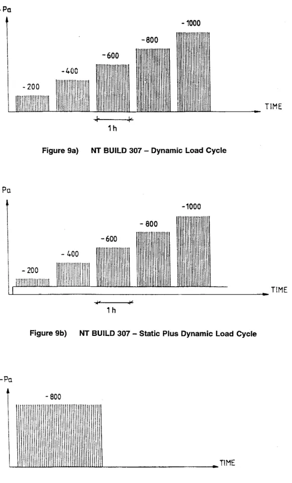
, 1995). To account for this condition in the testing procedure, a portion of the roofing insulation has been removed to create a slit with the bottom box. When static pressure is applied at the bottom box, first ths roof membrane above this portion is lifted up causing non-axial forces on the fasteners (ref.: Fig. 8).The loading program is designed to apply load intervals with increasing intensity where patterns can involve dynamic or a combination of static and dynamic loading. As shown in figure 9 (a), for one hour load interval suction is applied as gusts at every 15 seconds. The intensity is increased by 200 Pa between the load intervals. In addition to the above, a static suction is applied to lii the membrane (ref.: fig. 9 b). Loading can also be applied with a fixed intensity for longer period (ref.: fig. 10). In this case also the suction gusts are applied continuously at every 15 second.
1. Storage tank (11 m3) for
air
at low pressure2. Connection to fan for air evacuation
3. Valve to operate dynamic suction
4. Connection ta fan operating pulsating suction for standard
Figure 8 NT BUILD 307 Test Apparatus
-wind load testing
(NT
BUILD 307)Main air duct Upper box
Inspection window Flexible
air
tubes(7, with diam. 18 cmf
Air cooler
30 mm air intake slit
Holes to equalize pressure after gust
Roof membrane with fasteners Roof deck with insulation Section without insulation
Steel
frameLower box
Inspection manhole
Connection to fan operating static pressure for standard wind load testing
(NT
BUILD 307).TlME
Figure 9a) NT BUILD 307
-
Dynamic Load CycleTlME
Figure 9b) NT BUILD 307
-
Static Plus Dynamic Load CycleFigure 10) NT BUILD 307
-
Dynamic Load, Fixed Intensity Load PatternCHAPTER
3
CONCLUDING
REMARKS
3.1 SUMMARY
At present mechanically attached roof systems are evaluated using the FM 4470 and UL 580 procedures. However, these tests are insufficient since they do not considerthe effects of dynamic loading. In
Europe, fatigue has been acknowledged as an important factor in the evaluation of mechanically attached roof systems. Thus the European test methods are more realistic than those adopted in North America. In the following section, for the dynamic evaluation of roofing systems, a five step procedure is proposed.
3.2 PROPOSED EVALUATION PROCEDURE
Wind is random in nature so that simulating both the required amplitudes (pressure level) and the pressure variations with respect to time (frequency) is necessary. Figure 1 1 (a) shows a typical wind pressure fluctuation and its simplified representations. One of the best methods among the
simplifications is cyclic loading with sinusoidal formulation. This is because a dynamic wave form, such as, wind-induced pressure fluctuations, can be reconstructed using sine waves of different frequencies and amplitudes.
Evaluating the roofing assembly for high pressure alone does not identify how quick or slow that pressure varies with time on the assembly. Indeed to describe the process in time, wind spectral density functions are necessary. Figure 11 (b) shows the energy levels at diierent frequencies. These energy levels are deriied for the mean wind speed and they are significant up to about 10
Hz
in the wind spectrum. It is preferable to have a test facility in which the pressure level (magnitude) and the cycling rate (frequency) can be varied. Another acceptable way of obtaining this combination is simulating the design pressure levels at various frequencies. In this case, the roofing system has to undergo a series of tests, each one corresponding to a particular frequency. Then dynamic performance evaluation under wind conditions can be achieved by the following four step procedure:Step 1: Select the appropriate dynamic wind pressure for the building location from the building code or wind standards.
Step 2: Determine the recommended pressure coefficient value for the building assembly. (For a building with unusual shape, this value may be obtained through wind tunnel testing.)
Step 3: Calculate the test pressure (= pressure coefficient x dynamic wind pressure from step 1) Step 4: Identify the testing frequencies from the local wind velocity records.
Step 5: Simulate a condition with the test pressure calculated in Step 3 and evaluate for the above frequencies.
t
Time t
Frequency
(b)
Figure 11 Simplified representation of wind pressure used for testing
CHAPTER
4
REFERENCES
1. Baskaran, A.
(1986).
Wind Loads on Rat Roofs With and Without Parapets", M.Eng. Thesis, Concordia University, Montreal, Canada.2.
Baskaran, A. and Dm, 0.(1995).
"Evaluation of Roof Fasteners Under Dynamic Wind Loading" Proceedings of the 9th International Wind Engineering Conference, pp.1207
-1218.
3. Baskaran, A. and Kashef. A.
(1995),
"
Application of Numerical Models for the Dynamic Evaluation of Roofing System-
State of the Art Review". IRC Report #690,
National Research Council Canada, Ottawa, Canada.4. Bieber, S.
(1990).
"Hurricanes Test Roofs", Roofing Siding Insulation, January1990,
pp.60-61.
5. Byrne, S.M.
(1976).
"Dynamic-Load Testing of Sheet Metal Roofing", Metal Structures Conference, Adelaide, Australia, November25-26,1976,
pp.46-50.
6.
Carlson, J.(1992).
'FM and UI Wind Uplift Tests Still Not Understood By All", Roofing Siding Insulation, March1992,
p.72.
7.
Cook, N.J., Keevil, A.P. and Sfobart, R.K.(1988).
"BRERWULF- The big bad wolf', Journal of Wind Engineering and Industrial Aerodynamics, Vol.29,
1988,
pp.99-1
07.
8.
Dalgliesh, W.A.(1970).
Treatment of Peak Gusts on Cladding", Journal of Structural Engineering, ASCE,97,
(I),
p.2173.
9.
Decker, R. C.(1989).
"Technology Transfer: Roof Failures Pose Industry Alert", The Military Engineer, SeptemberIOctober1989,
p. 53.10.
Ellifritt, D.S. and Burnette, R.(1990).
"Pull-Over Strength of Screws in Simulated Building Tests", Tenth lnternational Specialty Conference on Cold-Formed Steel Structures. St. Louis, Missouri.11. Fricklas, D.
(1990).
"On The Roof: Knowing Mechanically Attached Roofs", Roofing Siding Insulation, April1990,
p.8.
12.
Factory Mutual Research, Approval Standard: Class I Roof Covers(4470),
April1986.
13. Factory Mutual Research, "In Search of Excellence ... FMRC Improves Roof Tests", The Roofing Industry Educational Institute Information Letter, Winter 1992, pp. 5-7.
14. Gerhardt. H.J. and Kramer, C. (1986). "Wind Induced Loading Cycle and Fatigue Testing of Lightweight Roofing Fixations", Journal of Wind Engineering and Industrial Aerodynamics, Vol. 23, pp. 237-247.
15. Gerhardt. H.J and Kramer, C. (1988). "Wind Loading and Fatigue Behavior of Fixings and Bondings of Roof Coverings", Journal of Wind Engineering and Industrial Aerodynamics, Vol. 29,
pp.
109-1 18. 16. Gerhardt, H.J. and Gerbatsch, R.W. (1989). "Testing Wind Loads on Single-Ply Membranes", TheConstruction Specifier, November 1989, pp. 61 -71.
17. Gerhardt, H.J. (1990). "Roofing Membranes--Observed Damage, Failure Modes, Failure Hypotheses and Laboratory testing", Proceedings of the Roof Wind Uplifi Testing Workshop, Oak Riisa, Tennessee, November 8-9,1989, pp. 19-34.
18. Gerhardt, H.J. and Gerbatsch, R.W. (1991). "Wind Resistance of Mechanically Attached, Single-Ply Systems. Fastener Load, Safety Considerations and Optimal Fastener Patterns", A Decade of Change and Future Trends in Roofing - 1991 international Symposium on Roofing Technology, NRCA, pp. 276-282.
19. Gutberlet. C.H., Jr. (1992). "Designing Against Wind", The Military Engineer, SeptemberIOctober 1992, pp. 46-47.
20. Hasan, R. and Ammerman, T. (1992). "Framing New Questions in FM Single-Ply Testing", Roofing Siding Insulation, May 1992, pp. 32-33.
21. Mahandran, M. (1990 a), "Static Behavior of Corrugated Roofing under Simulated Wind Loading", Transactions of the lnstitution of Engineers, Australia, Civil Engineering, Vol. CE 32, No. 4, pp. 212
-
21 8.22. Mahendran, M. (1990 b), "Fatigue Behavior of Corrugated Roofing under Cyclic Wind Loading",
Transactions of the Institution of Engineers, Australia, Civil Engineering, Vol. CE 32, No. 4, pp. 219
-
22623. Mahendran, M. (1994), " Effect of Overload Cycles on Thin Steel Roof Claddings during Cyclonic Winds", Journal of Testing and Evaluation, ASTM, Vol 22, No 5, pp 453-459.
24. Morgan, J.W. and Beck, V.R. (1977). "Failure of Sheet-Metal Roofing Under Repeated Wind Loading", Civil Engineering Transactions, The Institution of Engineers, Australia, Vol. CB19, January 1977, pp. 1-5.
25. Nordtest, Roof Coverings: Wind Load Resistance (NT BUILD 307) Nordtest, Finland, 1986.
26. O'Dea, T. (1990). "Oak Ridge Workshop Keys on Hugo Damage", Roofing Siding Insuhtion, January 1990, pp. 44-45.
27. Paulsen, E.M. (1989). "NBI Roof Wind Uplifl Strength Test Facility and Load Programs". Proceedings of the Roof Wind Uplift Testing Workshop, Oak Ridge, Tennessee, November 8-9, 1989, Pp. 46-51
28. Schroter, R.C. (1985). "Air Pressure Testing of Sheet Metal Roofing", A Decade of Change
and
Future Trends in Roofing, NRCA, pp. 254260.
29. Schroter, R.C. (1992). "Metal Roofing Standards", ASTM Standardization News, November 1992, pp. 66-71.
30. Underwriters Laboratories Inc., Standard for Uplift Pressure of Root Assemblies (UL 580), third edition. November 1991.
31. Warshaw, S.W. and Hoher, K. (1985). "Mechanical Fastening of Single-Ply Roof Membranes into Steel Decks--An Engineering Evaluation", A Decade of Change and Future Trends in Roofing--1985 Second International Symposium on Roofing Technology, pp. 183-193.
32. Zarghamee, M.S. (1990). "Wind Effects on Singleply Roofing Systems", Journal of Structural Engineering, Vol. 11 6, pp. 177-1 87.