Publisher’s version / Version de l'éditeur:
Journal of Engineering Mechanics, 114, 1, pp. 149-60, 1988-01
READ THESE TERMS AND CONDITIONS CAREFULLY BEFORE USING THIS WEBSITE. https://nrc-publications.canada.ca/eng/copyright
Vous avez des questions? Nous pouvons vous aider. Pour communiquer directement avec un auteur, consultez la première page de la revue dans laquelle son article a été publié afin de trouver ses coordonnées. Si vous n’arrivez pas à les repérer, communiquez avec nous à [email protected].
Questions? Contact the NRC Publications Archive team at
[email protected]. If you wish to email the authors directly, please see the first page of the publication for their contact information.
NRC Publications Archive
Archives des publications du CNRC
This publication could be one of several versions: author’s original, accepted manuscript or the publisher’s version. / La version de cette publication peut être l’une des suivantes : la version prépublication de l’auteur, la version acceptée du manuscrit ou la version de l’éditeur.
Access and use of this website and the material on it are subject to the Terms and Conditions set forth at
Model of ice rubble pileup
Sayed, M.; Frederking, R. M. W.
https://publications-cnrc.canada.ca/fra/droits
L’accès à ce site Web et l’utilisation de son contenu sont assujettis aux conditions présentées dans le site LISEZ CES CONDITIONS ATTENTIVEMENT AVANT D’UTILISER CE SITE WEB.
NRC Publications Record / Notice d'Archives des publications de CNRC:
https://nrc-publications.canada.ca/eng/view/object/?id=aee9d718-e9b3-483c-a1a8-c1610780391b https://publications-cnrc.canada.ca/fra/voir/objet/?id=aee9d718-e9b3-483c-a1a8-c1610780391bSer
TH1
r
National Research Conseil national Council Canada de rechaches Canada N2ldI Institute for lnstitut de
no*
Research inc . 2
'
recherche enConstruction construction
BLDG
Model of ice Rubble Pileup
by M. Sayed and R.M.W. Frederking
Reprinted from
Journal of Engineering Mechanics Vol. 114, No. 1, January 1988 p. 149-160
(IRC Paper No. 1505)
Price $3.00 NRCC 28648 N R C
-
Cf-L I B R A R Y
BIBLIOTHZQUE
I R C
CNR,"-
IClSTI
III
3
IIIIII(~
09IIIII~I
0 7III![IIII
5I\!\
R ~ S U M E
On prCsente ici un modkle de crCtes de pression en glace flottante. UII coin symktnque B
deux d~rnensionq est censk representer la voile (011 la quille) d'une crCte. Les auteurs se servent du nidt.le stochnstique de mnsfen des ccmtrainteq cln~ls !e< milieux p:~r.rictrInires et
dcs Cqu:irions d'Cqu11ibrc: pout dCtemilner la rtpnrt~t~on ties conlrillntes. Ils ne tiennent pas cotnpte de In cintm:\tlqt~r: du problkme d:m< leur annlyse. 11% ~~tilircnr le critPrc dc M o t ~ r - Co~~lrrtiib pcwr clf t r m i ~ n s r Ics 7orics de ruplure et. cn conl;c'~luence, lss Ii:i~~tc~rr et prtlit~ncleur limites dt: la cri.te. Le rnodi.1~ pr&vo~r 1;1 poussl't: exercic sur la cnuvenure de glrice en rapport :lvec la hauteur et la profondcur Ilrnitcs de In crtte, et il fournit des ~nforrnntions conccrnnnt I n gbomPtrie de cellc-ci. Lcs rCsultats sont con~p:~rt*.s ceux
ohtenus par dl;lu[rpc mjthmbr A a ~ n l e l ~ l 1 * e n n ~ ~ o c ~ r e c ( ~ ~ l r ~ ~ I ~ ~ ~ r~rnhlenf itre du meme
By M. Sayedl and R. M. W. Frederking2
ABSTRACT: A model of floating ice pressure ridges is developed. A
two-dimensional symmetric wedge is assumed to represent the sail (or keel) of a ridge. The stochastic model of stress transfer in particulate media and the equilibrium equations are used to determine the stress distribution. The kinematics of the problem are not considered in the analysis. The Mohr-Coulomb criterion is used to determine failure zones and consequently the limiting height and depth of the ridge. The model predicts forces in the ice cover associated with limiting ridge height and depth and gives some information about ridge geometry. The results are compared to other computation methods. Force predictions appear to be
c of the same order observed when floating ice impinges on wide struc-
tures.
When floating sea ice sheets are driven by environmental forces such as wind or current against shores or man-made structures, they break into small blocks. These blocks, which in the period immediately after their formation behave as a granular material with little or no cohesion, may accumulate to form a variety of features. Unlike flat slopes where an ice sheet may slide or "ride up," a steep obstacle will cause ice rubble to "pile up." The height and depth of floating rubble continue to increase as the ice sheet advances and breaks against previously formed rubble. After reach- ing a certain limiting height and depth, the rubble starts to grow horizon- tally. Similar rubble features, called pressure ridges, also occur when ice floes press against each other. In shallow water areas ( 1 2 5 m), keel depth can extend to the sea floor, thereby grounding the rubble.
Interest in ice rubble pileup has increased because of recent oil explo- rations in the Beaufort Sea. Estimates of the associated stresses and the limiting height and depth are important for designing drilling structures and marine pipelines. Floating ridges can also cause extreme loading con- ditions.
I
I A comprehensive description of many ice rubble features was given by
Zubov (1945). A recent review of available literature was given by Kovacs
i
and Sodhi (1980) and Sodhi and Kovacs (1984). Details of the morphologyI of pressure ridges may be found in papers by Weeks and Kovacs (1970)
1
and Tucker and Govoni (1981). Most field studies of rubble interaction with structures, however, remain proprietary. Published data include that of Strilchuk (1977) and Frederking and Wright (1982).Analytical treatment of this subject is still very limited. A kinematic
'Assoc. Res. Ofcr., Geotech. Section, Inst. for Res. in Construction, Natl. Res. Council of Canada, Ottawa, Ontario, Canada K I A 0R6.
2Sr. Res. Ofcr., Geotech. Section, Inst. for Res. in Construction, Natl. Res. Council of Canada, Ottawa, Ontario, Canada K I A 0R6.
Note. Discussion open until June 1, 1988. To extend the closing date one month, a written request must be filed with the ASCE Manager of Journals. The manuscript for this paper was submitted for review and possible publication on December 29, 1986. This paper is part of the Journal of Engineering Mechanics, Vol. 114, No. 1, January, 1988. OASCE, ISSN 0733-939918810001-0149/$1.00
+
$. 15 per page. Paper No. 22130.numerical model of pressure ridges was developed by Parmerter and Coon (1972). Although predicted ridge geometries appeared reasonable, the forces in the ice sheet associated with a certain ridge height could not be calculated directly. Parmerter and Coon suggested that a lower bound could be obtained by equating the work done by the ice sheet to the increase in the potential energy of the ridge. Their values ranged from lo2 to lo4 Nlm. Several authors (e.g., Kovacs and Sodhi 1980) used this potential energy method to derive a simple equation that gives the force in an ice sheet associated with rubble pileup. This equation gives forces of the order expected in an ice cover with length scales of several kilometers. In such a case, ridging or piling occurs only over part of the length at any instant. This sporadic behavior gives average forces lower than local forces. Ice rubble deforms more uniformly over smaller length scales (10 to 100 m), a situation relevant to most engineering applications. Indeed, measured ice forces on obstacles of these dimensions where rubble pileup occurs are of the order of a few hundred kilo-Newtons per meter (Strilchuk 1977; Frederking et al. 1985). The potential energy method grossly underestimates the forces in this case.
Kovacs and Sodhi (1980) added a frictional component by considering a simple case of a single layer of ice sliding over a rubble pileup or a shore. Visual accounts of rubble pileups (Zubov 1945; Kovacs and Sodhi 1980) suggest that more complex modes of deformation take place. Forces calculated by Kovacs and Sodhi approached reasonable values only for cases where the ice sheet slides for a long distance over a shore.
Simple shear tests by Prodanovic (1979) on model ice rubble show that bulk rubble obeyed the Mohr-Coulomb yield condition. Other laboratory experiments by Keinonen and Nyman (1978) and Tatinclaux and Cheng (1978) produced similar results. Those experiments gave angles of internal friction close to 50" with little or no cohesion. Consequently, Mellor (1980) treated the rubble as Mohr-Coulomb material to study some cases related to pileup. The writers (Sayed and Frederking 1984) developed a continuum model of ridges and pileups by considering the bulk rubble to be rigid- plastic obeying the Mohr-Coulomb yield criterion. Stresses in a wedge at the passive critical state were obtained.
This paper is aimed at predicting the limiting height and depth of a rubble pileup and the associated stresses. At this limiting state, parts of the rubble may be at a preyield condition. The plastic analysis (Sayed and Frederking 1984) is more suitable for the earlier stages of rubble pileup.
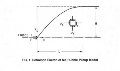
Consider an ice sheet advancing against a steep obstacle. Broken blocks form a buoyant wedge that grows horizontally after reaching the limiting height and depth. The weight of the sail would be equal to the buoyancy of the keel. It is assumed that the rubble has a two-dimensional symmetrical geometry, as shown in Fig. 1, which represents a sail or a keel. In this idealized model, the advancing ice sheet applies a horizontal load at the apex. A vertical body force acting downwards is taken as the bulk unit weight of the sail (or buoyancy of the keel). The model implies that an ice block may remain either in the sail or in the keel. The actual process might
F O R C E F,
F+I x
I L I
FIG. 1. Definition Sketch of Ice Rubble Pileup Model
be more complex than that, with an exchange of blocks between sail and keel.
Because available experimental data on broken ice do not give a stress-strain relationship, preyield behavior, which is important in the current case, cannot be defined. A stochastic model of normal stress distribution is used here to overcome this problem. The particulate nature of rubble and the relatively large size of blocks suggest that stresses are transmitted through random contacts.
Smoltczyk (1967) and Harr (1977) developed the theory for stochastic stress distribution in particulate media. A review of their theory is beyond the scope of this paper. They showed, however, that normal stresses applied at a boundary are distributed inside the bulk material according to the one-dimensional diffusion equation. The normal stress below a con- centrated load acting on a half-space would be Gaussian and, unlike linear elasticity, tensile stresses could be eliminated. The stochastic model was further developed by Chikwendu and Alimba (1979). Recently Golden (1985) presented a general treatment of this subject.
The two-dimensional equilibrium equations of the stresses and a one- dimensional diffusion equation for the distribution of the horizontal normal stress as predicted by particulate media models are used herein. In this connection, mass balance and strain-displacements relations are not used. The Mohr-Coulomb criterion is used to determine failure zones.
Deformation is assumed to be two-dimensional and relatively slow such that inertia of the rubble is negligible. The equilibrium equations in rectangular Cartesian coordinates x and y (Fig. 1) are as follows:
where o x , oy , and T are the normal and shear stress components (compressive normal stresses are considered positive); and y = the unit weight of bulk rubble (or buoyancy of the keel).
The normal horizontal stress distribution ax is assumed to follow the one-dimensional diffusion equation with x playing the role of the time variable (Chikwendu and Alimba 1979; Golden 1985; Harr 1977; Smoltczyk 1967). The diffusion coefficient has a dimension of length; it depends in general on the voids ratio and the shape and size distribution of the blocks. It was assumed in the references just cited that the diffusion coefficient increases linearly from the boundary on which external forces act. This eliminated tensile stresses, which cannot be sustained by cohesionless materials, and agreed more closely with experimental observations. Golden (1985) formally discussed the admissible functions describing the diffusion coefficient. The linear dependence on the distance x is the J simplest choice permitted by his theory. Thus, the horizontal normal stress distribution may be given by
dux
-- - V X
-
d2ux. . .
ax ay2 (3)
where v is a dimensionless coefficient. Chikwendu and Alimba (1979) calculated a value of 0.273 for v in the case of spherical particles with cubic (the loosest) packing. Intuitively, this value should increase for angular particles. Harr (1977) used a value that gives stress under a concentrated line load acting on a half-space equal to that of the Boussinesq elastic solution. This would result in a value of mi8 for v. There are no experimental data to determine the appropriate value for ice rubble. Still, the angularity and flakiness of typical blocks in ice rubble suggest a high value, possibly close to m18. Failure or rapid deformation of the bulk rubble is assumed to be governed by the linear Mohr-Coulomb criterion. Thus, failure occurs when
d
m
+722 (cx-
;
wy) sin 6. . .
(4) where
+
is the angle of internal friction. Unlike a perfect plasticity hypothesis, shear stresses are allowed to exceed the failure condition in part of the rubble. Other parts may not reach failure.STRESS DISTRIBUTION
The normal horizontal stress a, is governed by the parabolic partial differential equation (Eq. 3). Boundary conditions should be specified at the centerline and the stress-free surface. The initial condition at the apex is ox(0,y)=2F6(y)
. . .
(5) where 601) is the delta function and 2F is the line force. (A factor of two is used so that the force, F , acts on half the wedge.) The other two components of the stress tensor, uy and T, are obtained from the equilib-rium equations (Eqs. 1 and 2). Integrating Eq. 1 with respect to y and using Eq. 3 gives
The shear stress T and normal stress gradient 13aJdy should vanish at the
centerline. Therefore the integration constant was taken as zero. Inte- grating Eq. 2 with respect to y and using Eq. 3 gives
where C is a function of x.
The shear stress should be zero at the centerline O, = 0) and the top of the rubble [ y = yo(x)]. For large values of x the boundary elevation becomes y o z _ m ( ~ ) = H = constant. The solution of Eq. 3 is simplified by considering the boundary to be at yo(x) = H for all values of x. Thus
From observing the solution (presented later), it was felt that changing the boundary position for small values of x would not affect the solution appreciably (the decay of u, for small x). This approximation, albeit in the absence of mathematical justification, appears adequate to examine the validity of the current modeling approach. A more rigorous treatment would require an evolution equation for yo to be derived from the mass conservation (continuity) condition. Strains and displacements, however, are not included in the analysis because of the uncertainty regarding the appropriate constitutive equations. Such a method would increase the complexity of the solution without improving the accuracy.
Eq. 3 can be solved, subjected to the boundary conditions expressed in Eqs. 5 and 8, by using the method of images (Crank 1975). The stress distribution due to a line force 2F acting on a half-space (x r 0) is given by
. . .
Adding image forces at y =
+
2H,+
4H, 2 6H, to satisfy the boundaryconditions in Eq. 8, superposition gives
I
Substituting Eq. 10 in Eq. 6 gives the shear stress2F rn (y
+
2 n ~ ) 'C
(y+
2nH) exp[
- 2vx2]
. . .
= 2Considering that the normal stress a, should vanish at the boundary y = y o , from Eqs.,7 and 10
2F (y
+
2 n ~ ) ~ u y = ~ C Y o - y ) +i
{(Y + 2nHI2 exp[
- 2_2]
*x3 n = - m
- (yo
+
2 n ~ ) ~ exp[
- ~ ~ y ) ~ ] }. . .
(12) I The boundary height yo increases from zero at the origin to reach the I limiting height H at x = L as shown in Fig. 1. In the range 0 5 x 5 L , yo islimited by the vertical spread of the stresses a, and T. The determination
:
of yo is discussed later.
J
LIMITING HEIGHT
A horizontal force applied by the ice sheet will initially cause failure of the bulk rubble, which, as a result, can move upwards. The height ceases to increase when it approaches a value sufficient to prevent failure (upward movement) in the rubble. It is assumed that the limiting height H corresponding to a certain force is reached when stresses are at the critical passive state (given by Eq. 4 with ax 2 u,,) along a vertical plane. Any
further increase in H would reduce shear stresses to a prefailure state. Because of the choice of the boundary conditions, a, has a nonzero value but T and a,, are zero at y = H. Consequently, failure will always occur in
a layer near the top of the rubble. Since a layer of thickness less than a block size has no physical significance, any failure occurring in the top 10% of the rubble pileup height in the limiting case was ignored. This assump- tion is appropriate for most cases of interest.
, Rubble height yo in the sloping part of the pileup (x 5 L) should correspond to low stresses (ox) such that an increase in height would cause blocks to roll freely down the slope. The value of yo at a certain x may be calculated by trial and error. An approximation that seems to give reasonable results is to choose yo as the height at which ax (from Eq. 10) is reduced to a small fraction (taken as 0.1) of its maximum value (at y = 0).
ANALYSIS OF RESULTS
Results obtained for a stress diffusion coefficient v = 0.4 and an angle of internal friction
4
= 50" are presented later. Eqs. 10-12 were solved (using yo = H) to give the stress components a,, T, and a,,.
The value of H was incremented in steps for a given F. At each step, the failure condition was tested by substituting the calculated stresses in Eq. 4. This procedure was repeated for increasing x. The appropriate values of H and L are reached when failure occurs only in the top 10% of the wedge. Contours of the ratioDIMENSIONLESS HORIZONTAL DISTANCE, x/H
FIG. 2. Contours of Ratio of Maximum Shear Stress to Average Normal Stress Showlng Failure Zone in Rubble Pileup at Critical Height (I$ = 50°, v = 0.4) are shown in Fig. 2. Failure occurs when this ratio exceeds sin
+
(0.766 for+
= 50"). The resulting relationship between line force and limiting height for half a wedge isThe corresponding normal and shear stress distributions are shown in Figs. 3 and 4. The slope of the wedge in Fig. 2, which is approximately 45", is greater than the average values reported in the literature. Comparison with field observations is difficult, however, since measurements are always done after the pileup process is completed. Also, the current analysis assumed F is steady; a time-dependent F could change the slope.
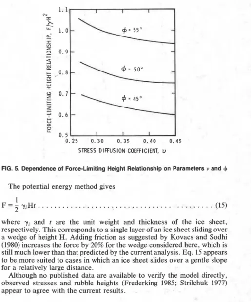
These values of parameters are likely to represent the properties of ice rubble as discussed earlier. Similar computations were carried out, how- ever, for a range of v from 0.27 to 0.45, and of
+
from 45 to 55", in order to examine sensitivity of the results to each parameter. Wedge geometry and stress distributions followed similar patterns as in Figs. 2-4. The relationship between force and limiting height for this range of parameter values is shown in Fig. 5.The force given by Eq. 13 is proportional to the square of the height of a sail or a keel. Since the pileup is neutrally buoyant, the ratio of sail to keel height' depends on their weight and buoyancy, respectively. Thus
1 . 0 I
-
X 0. 9 ; 0. 8 I" 0 . 7
-
Y 1 0.6 -I 0.5 0-
0.4 In Z w 0.3 I-
0.2g
0. 1 Z 0 0 1 2 3 4 5 6 7 8 9 1 0 N O N - D I M E N S I O N A L H O R I Z O N T A L N O R M A L S T R E S S . ux/yHFIG. 3. Horizontal Normal Stress Distribution
1.0 0.9 I
-
0. 8 c- 1 0. 7 I? Y 0.6 0 . 5 0 "7 0 . 4e
2
0.3 ?5
0.z
Z 0.1 0 0 1 2 3 0 1 2 3 NON-DIMENSIONAL NON-DIMENSIONAL VERTICAL NORMAL STRESS, SHEAR STRESS, T/yH"ylYH
FIG. 4. Vertical Normal Stress and Shear Stress Distribution
where F,
,
F,
,y,
, and y, are the forces associated with the sail and the keel, the unlt weight of the sail, and the buoyancy of the keel, respectively.Forces caldulated from Eq. 13 are compared with those predicted by
other methods in Fig. 6. A bulk weight of 6,600 N/m3 is used, which is typical of a pileup sail. As expected, plasticity analysis (Sayed and
Frederking 1984) gives higher forces because all of the rubble is assumed
to be at the critical state. That assumption would be appropriate for the early stages of deformation before the limiting height is reached.
0. 25 0. 30 0. 35 0.40 0.45 STRESS DIFFUSION COEFFICIENT, v
FIG. 5. Dependence of Force-Limiting Height Relationship on Parameters v and
+
The potential energy method gives
where yi and t are the unit weight and thickness of the ice sheet, respectively. This corresponds to a single layer of an ice sheet sliding over a wedge of height H. Adding friction as suggested by Kovacs and Sodhi (1980) increases the force by 20% for the wedge considered here, which is still much lower than that predicted by the current analysis. Eq. 15 appears to be more suited to cases in which an ice sheet slides over a gentle slope for a relatively large distance.
Although no published data are available to verify the model directly, observed stresses and rubble heights (Frederking 1985; Strilchuk 1977) appear to agree with the current results.
A model of floating ice rubble pileup has been developed. The stochastic model of stress transfer in particulate media was used to obtain the stress distribution in an idealized sail or keel of a pileup. The diffusion equation was solved using an approximate boundary condition (rectangular bound- ary). A more elaborate solution is still required to accurately solve the free boundary problem. Kinematics were not included in the analysis. A Mohr-Coulomb criterion was used to determine failure zones in the rubble and the limiting rubble height. Values of the stress diffusion coefficient were chosen according to plausible physical arguments. Parametric study showed that results can vary only within a relatively small range. Block
S A I L H E I G H T , m
FIG. 6. Comparison of Current Analysis with Other Methods (7 = 6,600 N/rn3,
4 = 50°, and v = 0.4)
size does not affect the parameters v and
+
and does not appear explicitly in the analysis.Force predictions appear to be of the order observed when floating ice impinges on wide structures. The current values are lower than those calculated using a plasticity analysis and substantially exceed those obtained from the potential energy method.
There is a need for field data concerning the geometry of a pileup during its formation, the limiting pileup height, and the associated force. Further experiments to determine the constitutive equations for bulk ice rubble are also needed.
This paper is a contribution from the Institute for Research in Construc- tion, National Research Council of Canada.
Chikwendu, S. C., and Alimba, M. (1979). ''Diffusion analogy for some stress computations." J. Geotechn. Engrg. Div., ASCE, 105(1 I), 1337-1342.
Crank, J. (1975). Mathematics of diffusion. Oxford University Press, London, England.
an ice rubble field, Issungnak, February-March 1980." Proc., Workshop on Sea Ice Ridging and Pile-Up, Technical Memorandum 134, Associate Commit- tee on Geotechnical Research, National Research Council of Canada, Calgary, - .
Canada, 230-246.
Frederking, R. M. W., et al. (1985). "Ice interaction with Adams Island, winter 1983184." Proc.. 7th Canadian Hvdrotechnical Conference, lB, May 27-31, Saskatoon, Canada, 365-387.
Golden, J. M. (1985). "Stochasic models of granular materials." J. Engrg.
Mech., ASCE, 110(1 I), 1610-1626.
Harr, M. E. (1977). Mechanics of particulate media. McGraw-Hill, New York, N.Y.
Keinonen, A., and Nyman, T. (1978). "An experimental model-scale study on the compressible, frictional and cohesive behaviour of broken ice mass."
I- Proc., International Association for Hydraulic Research Symposium on Ice
Problems, Lulea, Sweden, 335-353.
Kovacs, A., and Sodhi, D. S. (1980). "Shore ice pile-up and ride-up: Field observations, models, theoretical analyses." Cold Reg. Sci. Tech., 2(1), 20%288.
Mellor, M. (1980). "Ship resistance in thick brash ice." Cold Reg. Sci. Tech., 3(4), 305-321.
Parmerter, R. P., and Coon, M. D. (1972). "Model of pressure ridge formation in sea ice." J . Geophys. Res., 77(33), 6565-6575.
Prodanovic, A. (1979). "Model tests of ice rubble strength." Proc., Symposium on Port and Ocean Engineering under Arctic Conditions, Trondheim, Norway, 8%105.
Sayed, M., and Frederking, R. M. W. (1984). "Stresses in first-year pressure ridges." Proc., Third International Offshore Mechanics and Arctic Engineering Symposium, American Society of Mechanical Engineers, New Orleans, La., 3, 173-177.
Smoltczyk, H. U. (1967). "Stress computation in soil media." J. Soil Mech. and
Found. Div., ASCE, 93(2), 101-124.
Sodhi, D. S., and Kovacs, A. (1984). "Forces associated with ice pile-up and ride-up." Proc., International Association for Hydraulic Research Ice Symposium, Hamburg, Germany, 4, 23%262.
Strilchuk, A. R. (1977). "Ice pressure measurements, Netserk F-40, 1975-76." Arctic Petroleum Operators Association Project No. 106-1, available from Pallister Resource Management Ltd., 105-41 16 64th Ave., S.E., Calgary, Alberta, Canada.
Tatinclaux, J. C., and Cheng, S. T. (1978). "Characteristics of river ice jams."
Proc.. International Association for Hvdraulic Research Symposium on Ice - -
problems, Lulea, Sweden, 461-476.
Tucker 111, W. B., and Govoni, J. W. (1981). "Morphological investigations of first-year sea ice pressure ridge sails." Cold Reg. Sci. Tech., 5(1), 1-12. Weeks, W. F., and Kovacs, A. (1970). "The morphology and physical properties
of pressure ridges: Barrow, Alaska, April 1969." Proc., International Association for Hydraulic Research Ice Symposium, Reykjavik, Iceland. Zubov, N. N. (1945). Arctic Ice. Izdatel'stvo Glavsevmorputi, Moscow, USSR
(Translation AD426972, National Technical Information Service, Springfield, Va.).
APPENDIX II. NOTATION
The following symbols are used in this paper:
C = function of x in Eq. 6;
F = line force acting on half wedge;
H = limiting height (or depth) of rubble;
limiting height of sail; thickness of ice sheet; horizontal coordinate; vertical coordinate; unit weight of bulk rubble; unit weight of ice;
Delta function;
dimensionless stress diffusion coefficient; horizontal normal stress;
vertical normal stress; shear stress; and
I T h i s p a p e r i s b e i n g d i s t r i b u t e d i n r e p r i n t f o r m by t h e I n s t i t u t e f o r R e s e a r c h i n C o n s t r u c t i o n . A l i s t of b u i l d i n g p r a c t i c e and r e s e a r c h p u b l i c a t i o n s a v a i l a b l e from t h e I n s t i t u t e may be o b t a i n e d by w r i t i n g t o t h e P u b l i c a t i o n s S e c t i o n , I n s t i t u t e f o r R e s e a r c h i n C o n s t r u c t i o n , N a t i o n a l R e s e a r c h C o u n c i l o f C a n a d a , O t t a w a , O n t a r i o , KIA 0R6. Ce document e s t d i s t r i b u 6 s o u s forme de t i r s - 2 - p a r t p a r l 1 1 n s t i t u t de r e c h e r c h e e n c o n s t r u c t i o n . O n p e u t o b t e n i r une l i s t e d e s p u b l i c a t i o n s de 1' I n s t i t u t p o r t a n t s u r l e s t e c h n i q u e s ou l e s r e c h e r c h e s e n m a t i a r e d e b z t i m e n t e n C c r i v a n t 2 l a S e c t i o n d e s p u b l i c a t i o n s , I n s t i t u t de r e c h e r c h e en c o n s t r u c t i o n , C o n s e i l n a t i o n a l d e r e c h e r c h e s du Canada, Ottawa ( O n t a r i o ) , K I A ORb.